SUBARU FORESTER 2004 Service Repair Manual
Manufacturer: SUBARU, Model Year: 2004, Model line: FORESTER, Model: SUBARU FORESTER 2004Pages: 2870, PDF Size: 38.67 MB
Page 2171 of 2870

EN(H4DOTC 2.5)-147
ENGINE (DIAGNOSTIC)
Diagnostic Procedure with Diagnostic Trouble Code (DTC)
7 CHECK FUEL TANK CORD.
1) Turn the ignition switch to OFF.
2) Disconnect the connector from fuel sub
level sensor.
3) Measure the resistance between fuel sub
level sensor and chassis ground.
Connector & terminal
(R59) No. 1 — Chassis ground:Is the resistance more than 1
MΩ?Go to step 8.Repair ground
short circuit in fuel
tank cord.
8 CHECK FUEL TANK CORD.
1) Disconnect the connector from fuel pump
assembly.
2) Measure the resistance between fuel pump
assembly and chassis ground.
Connector & terminal
(R59) No. 2 — Chassis ground:Is the resistance more than 1
MΩ?Go to step 9.Repair ground
short circuit in fuel
tank cord.
9 CHECK FUEL LEVEL SENSOR.
1) Remove the fuel pump assembly.
2) Measure the resistance between fuel level
sensor and terminals with its float set to the full
position.
Te r m i n a l s
No. 2 — No. 3:Is the resistance 0.5 — 2.5 Ω? Go to step 10.Replace the fuel
level sensor.
10 CHECK FUEL SUB LEVEL SENSOR.
1) Remove the fuel sub level sensor.
2) Measure the resistance between fuel sub
level sensor and terminals with its float set to
the full position.
Te r m i n a l s
No. 1 — No. 2:Is the resistance 0.5 — 2.5 Ω? Repair poor con-
tact in harness
between ECM and
combination meter
connector.Replace the fuel
sub level sensor. Step Check Yes No
Page 2172 of 2870

EN(H4DOTC 2.5)-148
ENGINE (DIAGNOSTIC)
Diagnostic Procedure with Diagnostic Trouble Code (DTC)
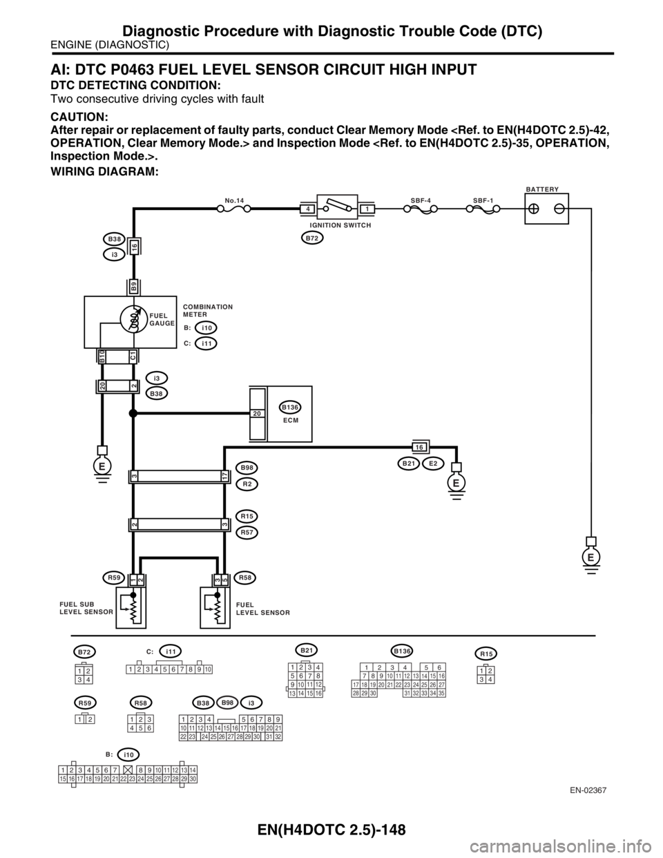
AI: DTC P0463 FUEL LEVEL SENSOR CIRCUIT HIGH INPUT
DTC DETECTING CONDITION:
Two consecutive driving cycles with fault
CAUTION:
After repair or replacement of faulty parts, conduct Clear Memory Mode
WIRING DIAGRAM:
EN-02367
B72
R59 R58B21
B136
i11
1
2345678910
R15 B136
ECM No.14
i10
B38
B21 E2
B98
R2 i3 B38
i3
E E E
FUEL
GAUGE
B:
i11 C: SBF-4 SBF-1
B721 4
B9 B10
C1
3
17
R15
R59R572 1
2
R583
53
16 20
12 1 3
4562123
4
56
78
9
1011 12
1314 15 16
C:
56
782 1
94 310
24 22 23 2511 12 13
1415
26 27
2816
17 18 19 20 21
33 34 29
32 30
31 35
2 20
16
BATTERY
IGNITION SWITCH
COMBINATION
METER
FUEL SUB
LEVEL SENSORFUEL
LEVEL SENSOR
3412
123456789101112131415161718192021222324252627282930
i10 B:
B38i3
3412
B98
219
32
1234
5610 11 12 13 14 15716
23 3019 20
22 26 27 28 29817
24 3118
25
Page 2173 of 2870

EN(H4DOTC 2.5)-149
ENGINE (DIAGNOSTIC)
Diagnostic Procedure with Diagnostic Trouble Code (DTC)
Step Check Yes No
1 CHECK SPEEDOMETER AND TACHOME-
TER OPERATION IN COMBINATION
METER.Does the speedometer and
tachometer operate normally?Go to step 2.Repair or replace
the combination
meter.
Meter System.>
2 CHECK INPUT SIGNAL FROM ECM.
1) Turn the ignition switch to ON. (engine OFF)
2) Measure the voltage between ECM con-
nector and chassis ground.
Connector & terminal
(B136) No. 20 (+) — Chassis ground (
−):Is the voltage more than 4.75
V?Go to step 3.Even if the malfunc-
tion indicator light
illuminates, the cir-
cuit has returned to
a normal condition
at this time. A tem-
porary poor contact
of the connector
may be the cause.
N
OTE:
In this case repair
the following:
Poor contact in
fuel pump connec-
tor
Poor contact in
coupling connector
3 CHECK INPUT VOLTAGE OF ECM.
1) Turn the ignition switch to OFF.
2) Disconnect the combination meter connec-
tor (i11) and ECM connector.
3) Turn the ignition switch to ON.
4) Measure the voltage of harness between
ECM and chassis ground.
Connector & terminal
(B136) No. 20 (+) — Chassis ground (
−):Is the voltage more than 4.75
V?Go to step 4.Repair battery
short circuit
between ECM and
combination meter
connector.
4 CHECK HARNESS BETWEEN ECM AND
FUEL TANK CORD.
1) Turn the ignition switch to OFF.
2) Separate fuel tank cord connector (R57)
and rear wiring harness connector (R15).
3) Measure the resistance between ECM and
fuel tank cord.
Connector & terminal
(B136) No. 20 — (R15) No. 7:Is the resistance less than 5
Ω?Go to step 5.Repair open circuit
between ECM and
fuel tank cord.
5 CHECK HARNESS BETWEEN FUEL TANK
CORD AND CHASSIS GROUND.
Measure the resistance between fuel tank cord
and chassis ground.
Connector & terminal
(R15) No. 3 — Chassis ground:Is the resistance less than 5
Ω?Go to step 6.Repair open circuit
between fuel tank
cord and chassis
ground.
N
OTE:
In this case repair
the following:
Poor contact in
coupling connector
6 CHECK FUEL TANK CORD.
1) Disconnect the connector from fuel level
sensor.
2) Measure the resistance between fuel level
sensor and coupler connector.
Connector & terminal
(R57) No. 3 — (R58) No. 5:Is the resistance less than 10
Ω?Go to step 7.Repair open circuit
between coupling
connector and fuel
level sensor.
Page 2174 of 2870

EN(H4DOTC 2.5)-150
ENGINE (DIAGNOSTIC)
Diagnostic Procedure with Diagnostic Trouble Code (DTC)
7 CHECK FUEL TANK CORD.
1) Disconnect the connector from fuel sub
level sensor.
2) Measure the resistance between fuel level
sensor and fuel sub level sensor.
Connector & terminal
(R58) No. 3 — (R59) No. 2:Is the resistance less than 10
Ω?Go to step 8.Repair open circuit
between fuel level
sensor and fuel
sub level sensor.
8 CHECK FUEL TANK CORD.
Measure the resistance between fuel sub level
sensor and coupler connector.
Connector & terminal
(R57) No. 2 — (R59) No. 1:Is the resistance less than 10
Ω?Go to step 9.Repair open circuit
between coupling
connector and fuel
sub level sensor.
9 CHECK FUEL LEVEL SENSOR.
1) Remove the fuel pump assembly.
2) While moving the fuel level sensor float up
and down, measure resistance between fuel
level sensor terminals.
Te r m i n a l s
No. 2 — No. 3:Is the resistance more than 53
Ω?Replace the fuel
level sensor.
2.5)-54, Fuel Level
Sensor.>Go to step 10.
10 CHECK FUEL SUB LEVEL SENSOR.
1) Remove the fuel sub level sensor.
2) While moving the fuel sub level sensor float
up and down, measure resistance between
fuel sub level sensor terminals.
Te r m i n a l s
No. 1 — No. 2:Is the resistance more than 45
Ω?Replace the fuel
sub level sensor.
55, Fuel Sub Level
Sensor.>Replace the com-
bination meter.
Meter Assembly.> Step Check Yes No
Page 2175 of 2870

EN(H4DOTC 2.5)-151
ENGINE (DIAGNOSTIC)
Diagnostic Procedure with Diagnostic Trouble Code (DTC)
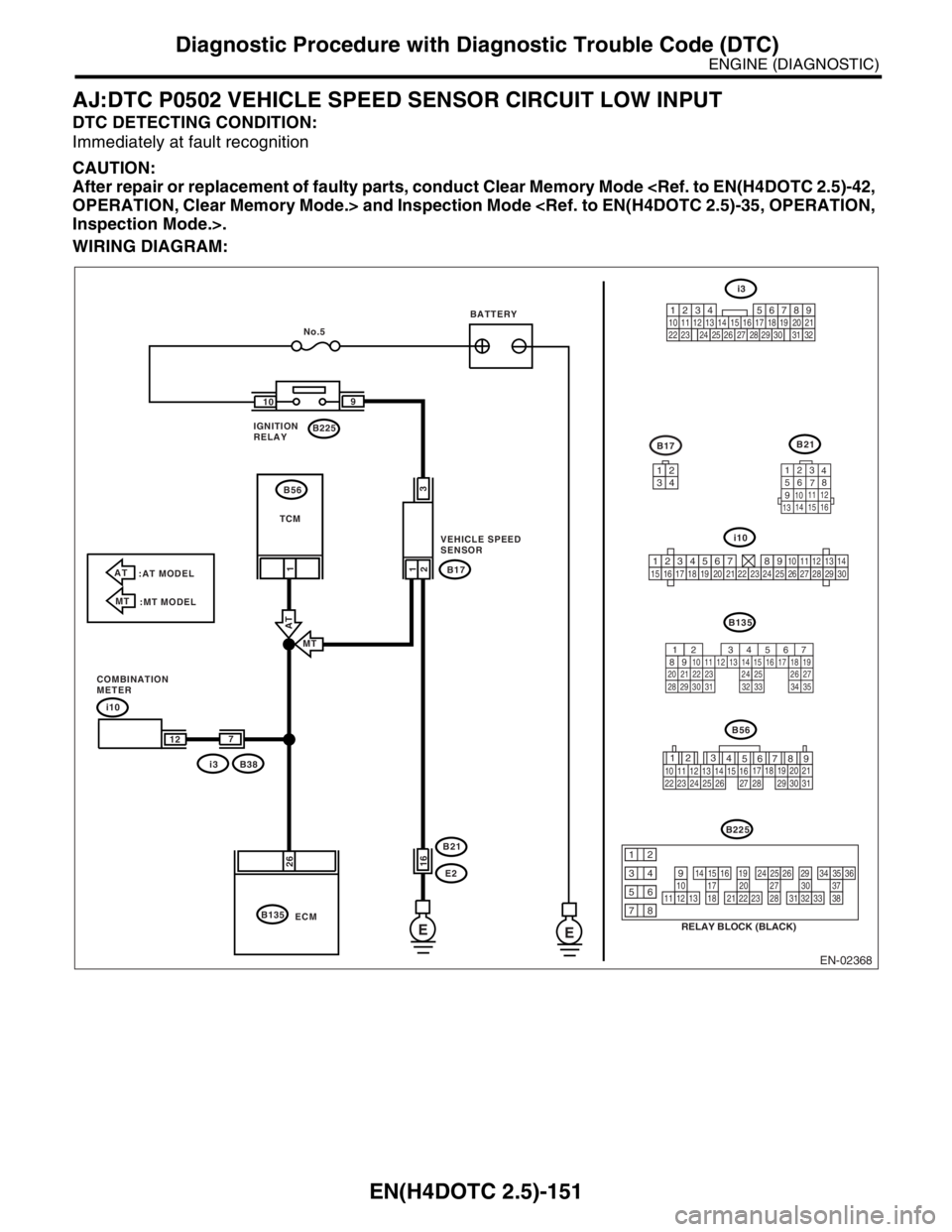
AJ:DTC P0502 VEHICLE SPEED SENSOR CIRCUIT LOW INPUT
DTC DETECTING CONDITION:
Immediately at fault recognition
CAUTION:
After repair or replacement of faulty parts, conduct Clear Memory Mode
WIRING DIAGRAM:
EN-02368
i10
B135B21
123
4
56
78
9
1011 12
1314 15 16
B17
i3
567
82 1
94 310
24 22 23 2511 12 13 14 15
26 27
2816 17 18 19
20 21
29 30 31 32 33 34 35
E E
i10
B38
i3B17
E2 B21
B135B225 109
26
2
21
1
No.5
ECM
3
16
7
12
AT
:AT MODEL
MT
:MT MODEL
MT
AT
IGNITION
RELAYBATTERY
TCM
VEHICLE SPEED
SENSOR
COMBINATION
METERB56
3412
123456789101112131415161718192021222324252627282930
12
789 56 3
410 11 1219 20 21
29 30 31 13 14 15 1617
27 2818
22 23 24 25 26
B56
B225
RELAY BLOCK (BLACK)
10111213
1415161718
1920212223
2425262728
2930313233
3435363738
12
934
56
78
219
32
1234 5610 11 12 13 14 15716
23 3019 20
22 26 27 28 29817
24 3118
25
Page 2176 of 2870

EN(H4DOTC 2.5)-152
ENGINE (DIAGNOSTIC)
Diagnostic Procedure with Diagnostic Trouble Code (DTC)
Step Check Yes No
1 CHECK HARNESS BETWEEN VEHICLE
SPEED SENSOR AND ECM CONNECTOR.
1) Turn the ignition switch to OFF.
2) Disconnect the connector from vehicle
speed sensor ECM.
3) Measure the resistance of harness
between vehicle speed sensor connector and
chassis ground.
Connector & terminal
(B17) No. 1 — Chassis ground:Is the resistance more than 1
MΩ?Go to step 2.Repair ground short
circuit in harness
between vehicle
speed sensor and
ECM connector.
2 CHECK POOR CONTACT.
Check poor contact in vehicle speed sensor
connector.Is there poor contact in vehicle
speed sensor connector?Repair poor con-
tact in vehicle
speed sensor con-
nector.Replace the vehi-
cle speed sensor.
Sensor.>
Page 2177 of 2870

EN(H4DOTC 2.5)-153
ENGINE (DIAGNOSTIC)
Diagnostic Procedure with Diagnostic Trouble Code (DTC)
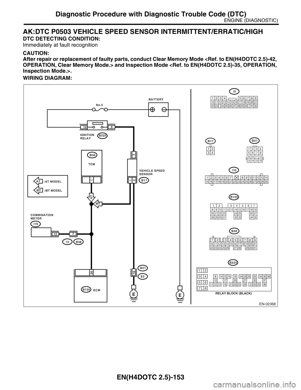
AK:DTC P0503 VEHICLE SPEED SENSOR INTERMITTENT/ERRATIC/HIGH
DTC DETECTING CONDITION:
Immediately at fault recognition
CAUTION:
After repair or replacement of faulty parts, conduct Clear Memory Mode
WIRING DIAGRAM:
EN-02368
i10
B135B21
123
4
56
78
9
1011 12
1314 15 16
B17
i3
567
82 1
94 310
24 22 23 2511 12 13 14 15
26 27
2816 17 18 19
20 21
29 30 31 32 33 34 35
E E
i10
B38
i3B17
E2 B21
B135B225 109
26
2
21
1
No.5
ECM
3
16
7
12
AT
:AT MODEL
MT
:MT MODEL
MT
AT
IGNITION
RELAYBATTERY
TCM
VEHICLE SPEED
SENSOR
COMBINATION
METERB56
3412
123456789101112131415161718192021222324252627282930
12
789 56 3
410 11 1219 20 21
29 30 31 13 14 15 1617
27 2818
22 23 24 25 26
B56
B225
RELAY BLOCK (BLACK)
10111213
1415161718
1920212223
2425262728
2930313233
3435363738
12
934
56
78
219
32
1234 5610 11 12 13 14 15716
23 3019 20
22 26 27 28 29817
24 3118
25
Page 2178 of 2870

EN(H4DOTC 2.5)-154
ENGINE (DIAGNOSTIC)
Diagnostic Procedure with Diagnostic Trouble Code (DTC)
Step Check Yes No
1 CHECK SPEEDOMETER OPERATION IN
COMBINATION METER.Does speedometer operate
normally?Go to step 2.Check the speed-
ometer.
eter.>
2 CHECK HARNESS BETWEEN ECM AND
COMBINATION METER CONNECTOR.
1) Turn the ignition switch to OFF.
2) Disconnect the connector from the combi-
nation meter.
3) Measure the resistance between ECM and
combination meter connector.
Connector & terminal
(B135) No. 26 — (i10) No. 12:Is the resistance less than 10
Ω?Repair the poor
contact in ECM
connector.Repair the harness
and connector.
N
OTE:
In this case repair
the following:
Open circuit in
harness between
ECM and combi-
nation meter con-
nector
Poor contact in
ECM connector.
Poor contact in
combination meter
connector
Poor contact in
coupling connector
Page 2179 of 2870

EN(H4DOTC 2.5)-155
ENGINE (DIAGNOSTIC)
Diagnostic Procedure with Diagnostic Trouble Code (DTC)
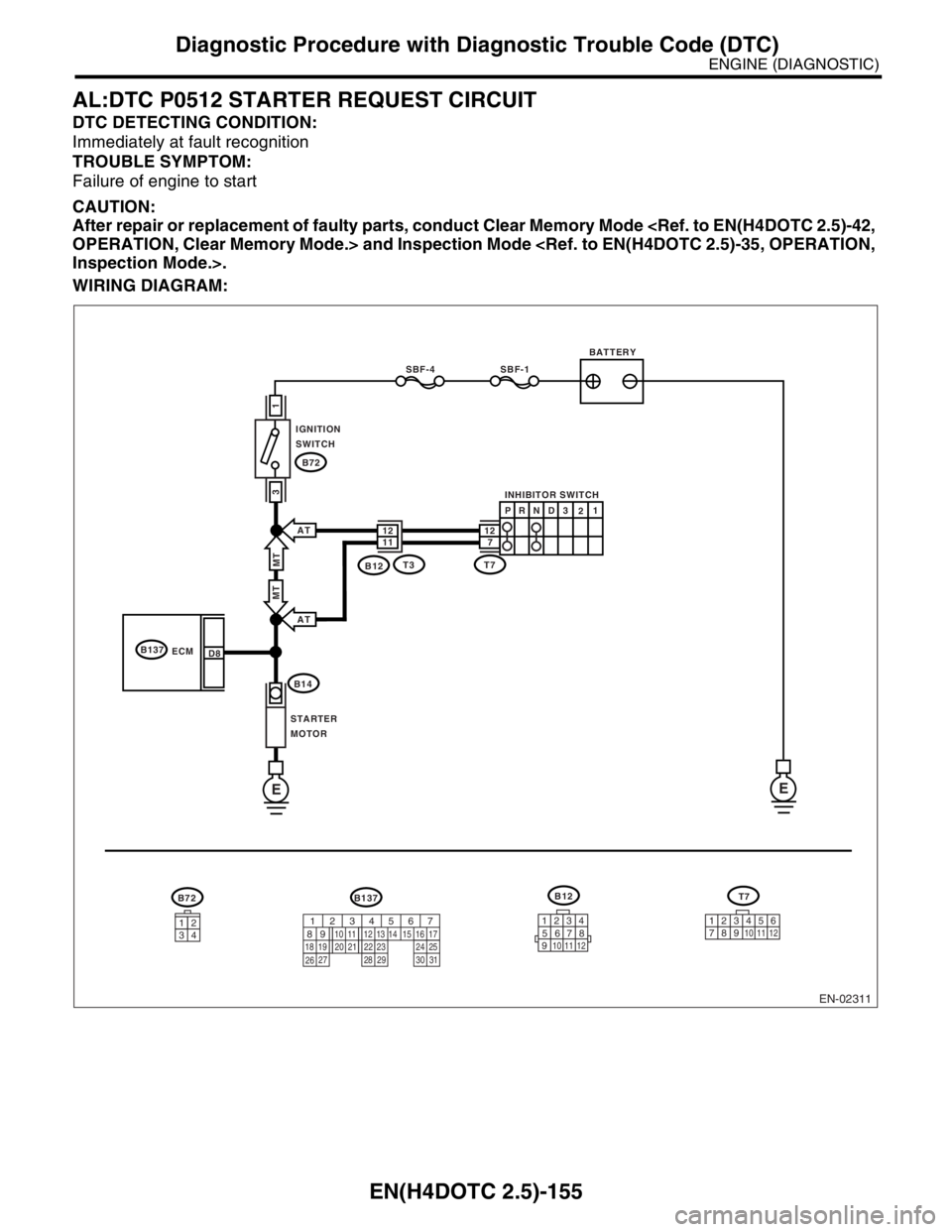
AL:DTC P0512 STARTER REQUEST CIRCUIT
DTC DETECTING CONDITION:
Immediately at fault recognition
TROUBLE SYMPTOM:
Failure of engine to start
CAUTION:
After repair or replacement of faulty parts, conduct Clear Memory Mode
WIRING DIAGRAM:
EN-02311
BATTERY
INHIBITOR SWITCH
IGNITION
SWITCH
STARTER
MOTOR
SBF-4SBF-1
B72
B72
B14
B137
ECM
EE
1
3
D8
3412
B137
T3B12MT
AT
AT
MT
1112712
PR
N
D3
21
T7
B12
123
8
9
10
4
11
1256
7
T7
123
8910411 1256
7567
82 1
94 310
22 23 11 12 13 14 15
24 25
2616 17
18 19 20 21
27 28 29 30 31
Page 2180 of 2870

EN(H4DOTC 2.5)-156
ENGINE (DIAGNOSTIC)
Diagnostic Procedure with Diagnostic Trouble Code (DTC)
Step Check Yes No
1 CHECK OPERATION OF STARTER MOTOR.Does the starter motor operate
when ignition switch to ON?Repair battery
short circuit in
starter motor cir-
cuit. After repair,
replace the ECM.
41, Engine Con-
trol Module
(ECM).>Check starter motor
circuit.
55, STARTER
MOTOR CIR-
CUIT, Diagnostics
for Engine Starting
Failure.>