SUBARU FORESTER 2004 Service Repair Manual
Manufacturer: SUBARU, Model Year: 2004, Model line: FORESTER, Model: SUBARU FORESTER 2004Pages: 2870, PDF Size: 38.67 MB
Page 211 of 2870

AB-79
AIRBAG SYSTEM (DIAGNOSTIC)
Diagnostic Procedure with Diagnostic Trouble Code (DTC)
Step Check Yes No
1 CHECK SIDE AIRBAG MODULE.
1) Turn the ignition switch to OFF, disconnect
the battery ground cable, and wait more than
20 seconds.
2) Disconnect the connector (AB9) from side
airbag module (LH), and connect the connec-
tor (1F) in test harness F to (AB9).
3) Connect the airbag resistor to connector
(3F) in test harness F.
4) Connect the battery ground cable and turn
the ignition switch to ON.Is the airbag warning light
turned on normally?Replace the front
seat with side air-
bag module (LH).
2 CHECK SIDE AIRBAG HARNESS (LH).
1) Turn the ignition switch to OFF, disconnect
the battery ground cable, and wait more than
20 seconds.
2) Disconnect the connector (AB19) from the
seat belt pretensioner (LH).
3) Disconnect the airbag resistor from the test
harness.
4) Disconnect the connector (AB7) from the
airbag control module.
5) Connect the connector (1R) in test harness
R to connector (AB7).
6) Connect the battery ground cable, and turn
the ignition switch to ON.
7) Measure the voltage between connector
(3R) in test harness R and the chassis ground.
Connector & terminal
(3R) No. 10 (+) — Chassis ground (
−):
(3R) No. 12 (+) — Chassis ground (
−): Is the voltage less than 1 V? Replace the airbag
control module.
Module.>Replace the side
airbag harness
with body harness.
Page 212 of 2870

AB-80
AIRBAG SYSTEM (DIAGNOSTIC)
Diagnostic Procedure with Diagnostic Trouble Code (DTC)
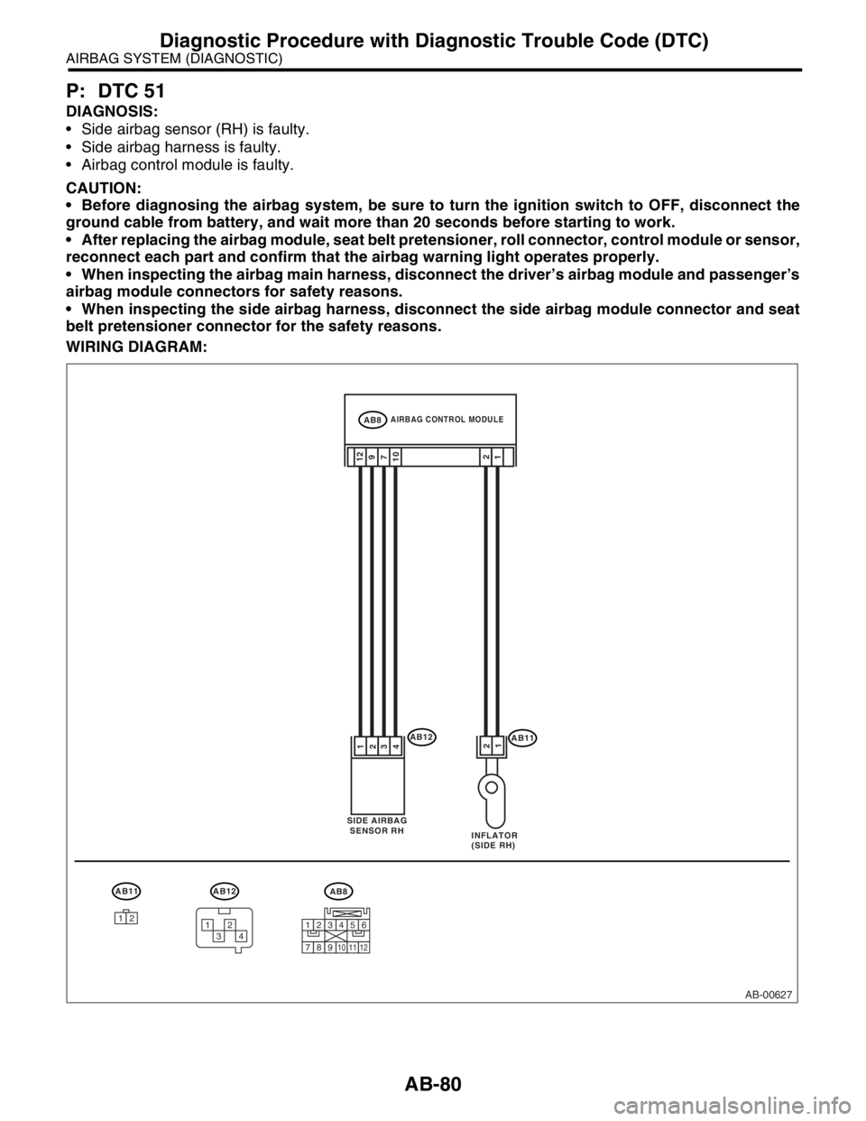
P: DTC 51
DIAGNOSIS:
Side airbag sensor (RH) is faulty.
Side airbag harness is faulty.
Airbag control module is faulty.
CAUTION:
Before diagnosing the airbag system, be sure to turn the ignition switch to OFF, disconnect the
ground cable from battery, and wait more than 20 seconds before starting to work.
After replacing the airbag module, seat belt pretensioner, roll connector, control module or sensor,
reconnect each part and confirm that the airbag warning light operates properly.
When inspecting the airbag main harness, disconnect the driver’s airbag module and passenger’s
airbag module connectors for safety reasons.
When inspecting the side airbag harness, disconnect the side airbag module connector and seat
belt pretensioner connector for the safety reasons.
WIRING DIAGRAM:
AB-00627
AIRBAG CONTROL MODULEAB8
SIDE AIRBAG
SENSOR RH
INFLATOR
(SIDE RH)
AB111 2
12AB12
12
109
7
3
4
1
2
AB8
123456
789101112
AB12
3412
AB11
12
Page 213 of 2870

AB-81
AIRBAG SYSTEM (DIAGNOSTIC)
Diagnostic Procedure with Diagnostic Trouble Code (DTC)
Step Check Yes No
1 CHECK SIDE AIRBAG (RH) HARNESS.
1) Turn the ignition switch to OFF, disconnect
the battery ground cable, and wait more than
20 seconds.
2) Disconnect the connector (AB20) from the
seat belt pretensioner (RH).
3) For the vehicle with lap seat belt preten-
sioner, disconnect the connector (AB25) from
lap pretensioner.
4) Disconnect the connector (AB11) from side
airbag module (RH).
5) Disconnect the connector (AB8) from the
airbag control module.
6) Connect the connector (1R) in test harness
R to the connector (AB8).
7) Disconnect the connector (AB12) from the
side airbag sensor (RH), and connect the con-
nector (1G) in test harness G to connector
(AB12).
8) Measure the resistance between connector
(4R) in test harness R and connector (3G) in
test harness G.
Connector & terminal
(4R) No. 5 — (3G) No. 2:
(4R) No. 6 — (3G) No. 4:
(4R) No. 7 — (3G) No. 1:
(4R) No. 8 — (3G) No. 5: Is the resistance less than 10
Ω?Go to step 2.Replace the side
airbag harness
with body harness.
2 CHECK SIDE AIRBAG HARNESS.
Measure the resistance between connector
(4R) in test harness R and the chassis ground.
Connector & terminal
(4R) No. 5 — Chassis ground:
(4R) No. 6 — Chassis ground:
(4R) No. 7 — Chassis ground:
(4R) No. 8 — Chassis ground:Is the resistance more than 1
MΩ?Replace the side
airbag sensor
(RH).
Sensor.> When
sensor replace-
ment is not OK,
replace the airbag
control module.
Module.>Replace the side
airbag harness
with body harness.
Page 214 of 2870

AB-82
AIRBAG SYSTEM (DIAGNOSTIC)
Diagnostic Procedure with Diagnostic Trouble Code (DTC)
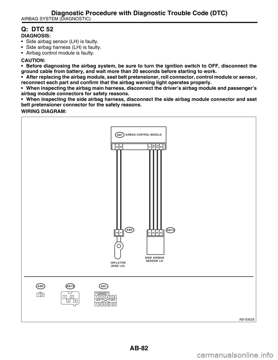
Q: DTC 52
DIAGNOSIS:
Side airbag sensor (LH) is faulty.
Side airbag harness (LH) is faulty.
Airbag control module is faulty.
CAUTION:
Before diagnosing the airbag system, be sure to turn the ignition switch to OFF, disconnect the
ground cable from battery, and wait more than 20 seconds before starting to work.
After replacing the airbag module, seat belt pretensioner, roll connector, control module or sensor,
reconnect each part and confirm that the airbag warning light operates properly.
When inspecting the airbag main harness, disconnect the driver’s airbag module and passenger’s
airbag module connectors for safety reasons.
When inspecting the side airbag harness, disconnect the side airbag module connector and seat
belt pretensioner connector for the safety reasons.
WIRING DIAGRAM:
AB-00628
AIRBAG CONTROL MODULEAB7
SIDE AIRBAG
SENSOR LH
INFLATOR
(SIDE LH)
AB1012
6 5AB9
12 10
9 7
3
4
1
2
AB10
3412
AB9
12
AB7
123456
789101112
Page 215 of 2870

AB-83
AIRBAG SYSTEM (DIAGNOSTIC)
Diagnostic Procedure with Diagnostic Trouble Code (DTC)
Step Check Yes No
1 CHECK SIDE AIRBAG (LH) HARNESS.
1) Turn the ignition switch to OFF, disconnect
the battery ground cable, and wait more than
20 seconds.
2) Disconnect the connector (AB19) from the
seat belt pretensioner (LH).
3) Disconnect the connector (AB9) from side
airbag module (LH).
4) Disconnect the connector (AB7) from the
airbag control module.
5) Connect the connector (1R) in test harness
R to connector (AB7).
6) Disconnect the connector (AB10) from the
side airbag sensor (LH), and connect the con-
nector (1G) in test harness G to connector
(AB10).
7) Measure the resistance between connector
(4R) in test harness R and connector (3G) in
test harness G.
Connector & terminal
(4R) No. 4 — (3G) No. 2:
(4R) No. 3 — (3G) No. 4:
(4R) No. 2 — (3G) No. 1:
(4R) No. 1 — (3G) No. 5:Is the resistance less than 10
Ω?Go to step 2.Replace the side
airbag harness
with body harness.
2 CHECK SIDE AIRBAG (LH) HARNESS.
Measure the resistance between connector
(4R) in test harness R and the chassis ground.
Connector & terminal
(4R) No. 4 — Chassis ground:
(4R) No. 3 — Chassis ground:
(4R) No. 2 — Chassis ground:
(4R) No. 1 — Chassis ground:Is the resistance more than 1
MΩ?Replace the side
airbag sensor
(LH).
Sensor.> When
sensor replace-
ment is not OK,
replace the airbag
control module.
Module.>Replace the side
airbag harness
with body harness.
Page 216 of 2870

AB-84
AIRBAG SYSTEM (DIAGNOSTIC)
Diagnostic Procedure with Diagnostic Trouble Code (DTC)
R: DTC 53
DIAGNOSIS:
Side airbag sensor (RH) is faulty.
When Code 53 is displayed, the circuit within the side airbag sensor (RH) is faulty. Replace the side airbag
sensor (RH).
S: DTC 54
DIAGNOSIS:
Side airbag sensor (LH) is faulty.
When Code 53 is displayed, the circuit within the side airbag sensor (LH) is faulty. Replace the side airbag
sensor (LH).
T: DTC 55
This code is displayed when the side airbag is operate.
When this code is displayed, the memory cannot be erased. Replace the following parts.
Airbag control module.
Front seat with side airbag module. (Operating side)
Side airbag sensor. (Operating side)
Page 217 of 2870

AB-85
AIRBAG SYSTEM (DIAGNOSTIC)
Diagnostic Procedure with Diagnostic Trouble Code (DTC)
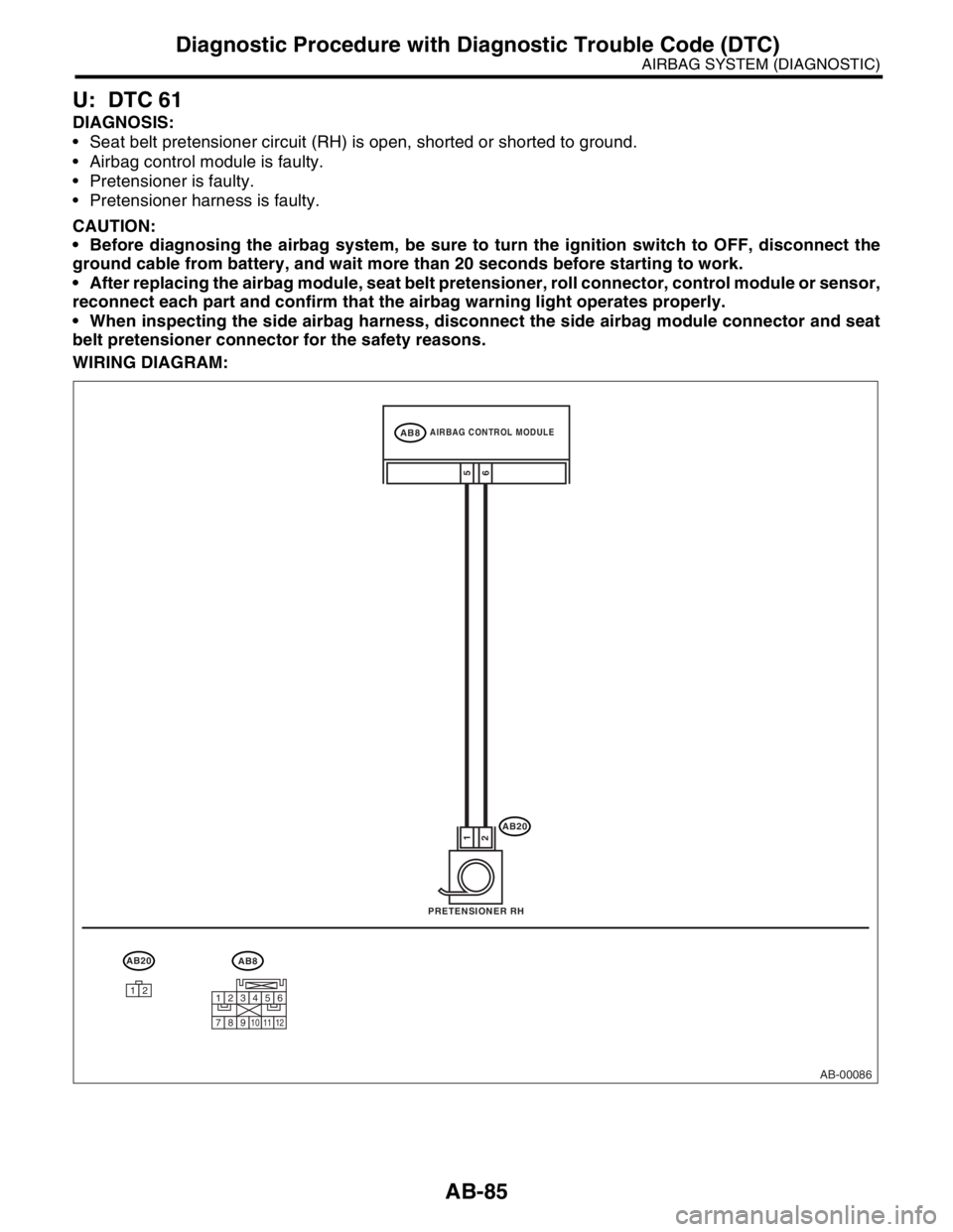
U: DTC 61
DIAGNOSIS:
Seat belt pretensioner circuit (RH) is open, shorted or shorted to ground.
Airbag control module is faulty.
Pretensioner is faulty.
Pretensioner harness is faulty.
CAUTION:
Before diagnosing the airbag system, be sure to turn the ignition switch to OFF, disconnect the
ground cable from battery, and wait more than 20 seconds before starting to work.
After replacing the airbag module, seat belt pretensioner, roll connector, control module or sensor,
reconnect each part and confirm that the airbag warning light operates properly.
When inspecting the side airbag harness, disconnect the side airbag module connector and seat
belt pretensioner connector for the safety reasons.
WIRING DIAGRAM:
AB-00086
12
AIRBAG CONTROL MODULEAB8
PRETENSIONER RH
AB20
AB20
6 1
25
AB8
123456
789101112
Page 218 of 2870

AB-86
AIRBAG SYSTEM (DIAGNOSTIC)
Diagnostic Procedure with Diagnostic Trouble Code (DTC)
Step Check Yes No
1 CHECK SEAT BELT PRETENSIONER.
1) Turn the ignition switch to OFF, disconnect
the battery ground cable, and wait more than
20 seconds.
2) Disconnect the connector (AB20) from the
seat belt pretensioner (RH).
3) Connect the connector (1F) in test harness
F to (AB20).
4) Connect the airbag resistor to connector
(3F) in test harness F.
5) Connect the battery ground cable and turn
the ignition switch to ON.Is the airbag warning light
turned on normally?Replace the seat
belt pretensioner
(RH).
Belt.>Go to step 2.
2 CHECK SIDE AIRBAG HARNESS (RH).
1) Turn the ignition switch to OFF, disconnect
the battery ground cable, and wait more than
20 seconds.
2) Disconnect the airbag resistor from the test
harness.
3) Disconnect the connector (AB11) from side
airbag module (RH).
4) Disconnect the connectors (AB7) and
(AB8) from the airbag control module.
5) Connect the connector (1R) in test harness
R to connector (AB8).
6) Measure the resistance between connector
(3R) in test harness R and connector (3F) in
test harness F.
Connector & terminal
(3R) No. 17 — (3F) No. 3:
(3R) No. 19 — (3F) No. 4: Is the resistance less than 10
Ω?Go to step 3.Replace the side
airbag harness
with body harness.
3 CHECK SIDE AIRBAG HARNESS (RH).
Measure the resistance of the connector (3R)
in test harness R.
Connector & terminal
(3R) No. 17 — (3R) No. 19: Is the resistance more than 1
MΩ?Go to step 4.Replace the side
airbag harness
with body harness.
4 CHECK SIDE AIRBAG HARNESS (RH).
Measure the resistance between connector
(3R) in test harness R and the chassis ground.
Connector & terminal
(3R) No. 17 — Chassis ground:
(3R) No. 19 — Chassis ground: Is the resistance more than 1
MΩ?Replace the airbag
control module.
Module.>Replace the side
airbag harness
with body harness.
Page 219 of 2870

AB-87
AIRBAG SYSTEM (DIAGNOSTIC)
Diagnostic Procedure with Diagnostic Trouble Code (DTC)
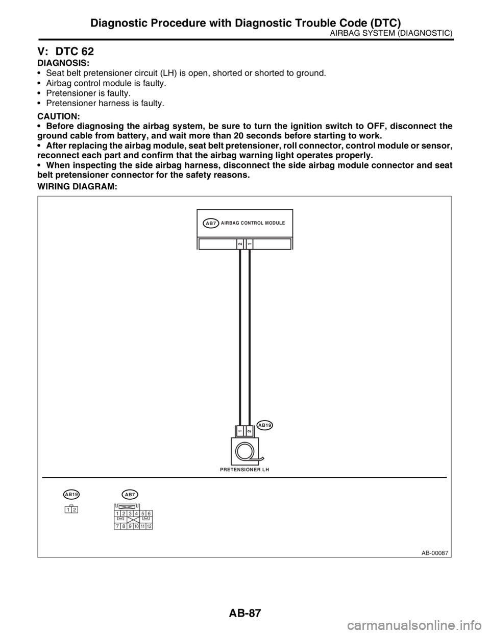
V: DTC 62
DIAGNOSIS:
Seat belt pretensioner circuit (LH) is open, shorted or shorted to ground.
Airbag control module is faulty.
Pretensioner is faulty.
Pretensioner harness is faulty.
CAUTION:
Before diagnosing the airbag system, be sure to turn the ignition switch to OFF, disconnect the
ground cable from battery, and wait more than 20 seconds before starting to work.
After replacing the airbag module, seat belt pretensioner, roll connector, control module or sensor,
reconnect each part and confirm that the airbag warning light operates properly.
When inspecting the side airbag harness, disconnect the side airbag module connector and seat
belt pretensioner connector for the safety reasons.
WIRING DIAGRAM:
AB-00087
12
AIRBAG CONTROL MODULEAB7
PRETENSIONER LH
AB19
AB19
1 1
22
AB7
123456
789101112
Page 220 of 2870

AB-88
AIRBAG SYSTEM (DIAGNOSTIC)
Diagnostic Procedure with Diagnostic Trouble Code (DTC)
Step Check Yes No
1 CHECK SEAT BELT PRETENSIONER.
1) Turn the ignition switch to OFF, disconnect
the battery ground cable, and wait more than
20 seconds.
2) Disconnect the connector (AB19) from the
seat belt pretensioner (LH).
3) Connect the connector (1F) in test harness
F to (AB19).
4) Connect the airbag resistor to the connec-
tor (3F) in test harness F.
5) Connect the battery ground cable and turn
the ignition switch to ON.Is the airbag warning light
turned on normally?Replace the seat
belt pretensioner
(LH).
Belt.>Go to step 2.
2 CHECK SIDE AIRBAG HARNESS (LH).
1) Turn the ignition switch to OFF, disconnect
the battery ground cable, and wait more than
20 seconds.
2) Disconnect the airbag resistor from the test
harness.
3) Disconnect the connector (AB9) from side
airbag module (LH).
4) Disconnect the connectors (AB7) and
(AB8) from the airbag control module.
5) Connect the connector (1R) in test harness
R to the connector (AB7).
6) Measure the resistance between connector
(3R) in test harness R and the connector (3F)
in test harness F.
Connector & terminal
(3R) No. 11 — (3F) No. 3:
(3R) No. 13 — (3F) No. 4: Is the resistance less than 10
Ω?Go to step 3.Replace the side
airbag harness
with body harness.
3 CHECK SIDE AIRBAG (LH) HARNESS.
Measure the resistance of the connector (3R)
in test harness R.
Connector & terminal
(3R) No. 11 — (3R) No. 13: Is the resistance more than 1
MΩ?Go to step 4.Replace the side
airbag harness
with body harness.
4 CHECK SIDE AIRBAG (LH) HARNESS.
Measure the resistance between the connector
(3R) in test harness R and the chassis ground.
Connector & terminal
(3R) No. 11 — Chassis ground:
(3R) No. 13 — Chassis ground: Is the resistance more than 1
MΩ?Replace the airbag
control module.
Module.>Replace the side
airbag harness
with body harness.