SUBARU FORESTER 2004 Service Repair Manual
Manufacturer: SUBARU, Model Year: 2004, Model line: FORESTER, Model: SUBARU FORESTER 2004Pages: 2870, PDF Size: 38.67 MB
Page 231 of 2870
AB-99
AIRBAG SYSTEM (DIAGNOSTIC)
Diagnostic Procedure with Diagnostic Trouble Code (DTC)
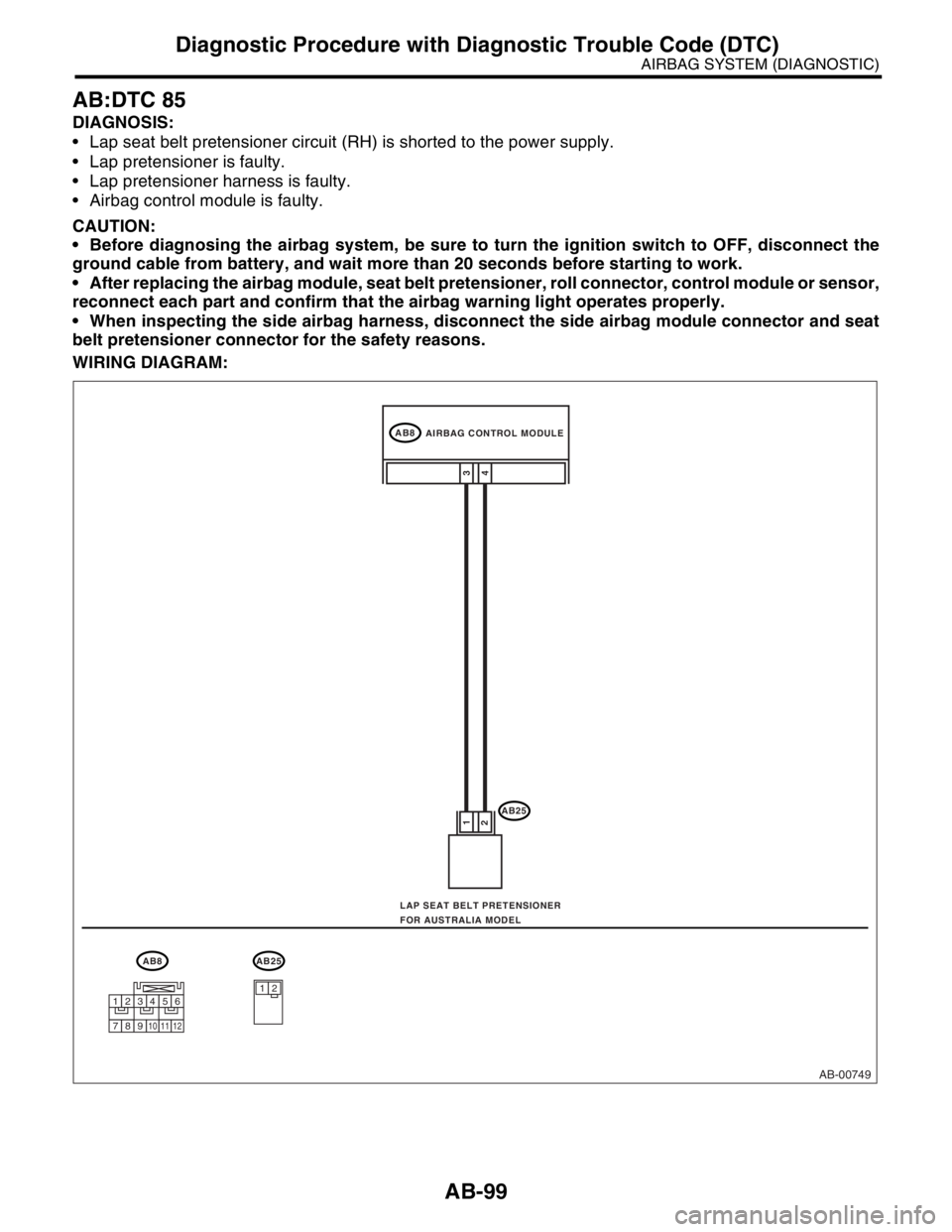
AB:DTC 85
DIAGNOSIS:
Lap seat belt pretensioner circuit (RH) is shorted to the power supply.
Lap pretensioner is faulty.
Lap pretensioner harness is faulty.
Airbag control module is faulty.
CAUTION:
Before diagnosing the airbag system, be sure to turn the ignition switch to OFF, disconnect the
ground cable from battery, and wait more than 20 seconds before starting to work.
After replacing the airbag module, seat belt pretensioner, roll connector, control module or sensor,
reconnect each part and confirm that the airbag warning light operates properly.
When inspecting the side airbag harness, disconnect the side airbag module connector and seat
belt pretensioner connector for the safety reasons.
WIRING DIAGRAM:
AB-00749
AB8
AB25
4 1
23
AB8AB25
12
AIRBAG CONTROL MODULE
LAP SEAT BELT PRETENSIONER
FOR AUSTRALIA MODEL
123456
789101112
Page 232 of 2870

AB-100
AIRBAG SYSTEM (DIAGNOSTIC)
Diagnostic Procedure with Diagnostic Trouble Code (DTC)
Step Check Yes No
1 CHECK LAP SEAT BELT PRETENSIONER.
1) Turn the ignition switch to OFF, disconnect
the battery ground cable, and wait more than
20 seconds.
2) Disconnect the connector (AB25) from the
lap seat belt pretensioner (RH).
3) Connect the connector (1Q) in test harness
Q to (AB25).
4) Connect the airbag resistor to the connec-
tor (2Q) in test harness Q.
5) Connect the battery ground cable and turn
the ignition switch to ON.Is the airbag warning light
turned on normally?Replace the lap
seat belt preten-
sioner (RH).
OUTER SEAT
BELT WITH LAP
SEAT BELT PRE-
TENSIONER,
REMOVAL, Front
Seat Belt.>Go to step 2.
2 CHECK SIDE AIRBAG HARNESS (RH).
1) Turn the ignition switch to OFF, disconnect
the battery ground cable, and wait more than
20 seconds.
2) Disconnect the airbag resistor from the test
harness.
3) Disconnect the connector (AB11) from side
airbag module (RH).
4) Disconnect the connector (AB20) from seat
belt pretensioner.
5) Disconnect the connectors (AB7) and
(AB8) from the airbag control module.
6) Connect the connector (1R) in test harness
R to the connector (AB7).
7) Connect the battery ground cable and turn
the ignition switch to ON.
8) Measure the voltage between connector
(3R) in test harness R and the chassis ground.
Connector & terminal
(3R) No. 2 (+) — Chassis ground (
−):
(3R) No. 4 (+) — Chassis ground (
−): Is the voltage less than 1 V? Replace the airbag
control module.
Module.>Replace the side
airbag harness
with body harness.
Page 233 of 2870
FUJI HEAVY INDUSTRIES LTD. G8080GE7
2004 FORESTER SERVICE MANUAL QUICK REFERENCE INDEX
BODY SECTION
This service manual has been prepared
to provide SUBARU service personnel
with the necessary information and data
for the correct maintenance and repair
of SUBARU vehicles.
This manual includes the procedures
for maintenance, disassembling, reas-
sembling, inspection and adjustment of
components and diagnostics for guid-
ance of experienced mechanics.
Please peruse and utilize this manual
fully to ensure complete repair work for
satisfying our customers by keeping
their vehicle in optimum condition.
When replacement of parts during
repair work is needed, be sure to use
SUBARU genuine parts.
All information, illustration and specifi-
cations contained in this manual are
based on the latest product information
available at the time of publication
approval.HVAC SYSTEM
(HEATER, VENTILATOR AND A/C)AC
HVAC SYSTEM (AUTO A/C)
(DIAGNOSTIC)AC
AIRBAG SYSTEM AB
AIRBAG SYSTEM (DIAGNOSTIC) AB
SEAT BELT SYSTEM SB
LIGHTING SYSTEM LI
WIPER AND WASHER SYSTEM WW
ENTERTAINMENT ET
COMMUNICATION SYSTEM COM
GLASS/WINDOW/MIRROR GW
BODY STRUCTURE BS
INSTRUMENTATION/DRIVER INFO IDI
SEAT SE
SECURITY AND LOCK SL
SUNROOF/T-TOP/CONVERTIBLE TOP
(SUNROOF)SR
EXTERIOR/INTERIOR TRIM EI
EXTERIOR BODY PANEL EB
Page 234 of 2870
2004 FORESTER SERVICE MANUAL QUICK REFERENCE INDEX
BODY SECTION
G8080GE7
CRUISE CONTROL SYSTEM CC
CRUISE CONTROL SYSTEM
(DIAGNOSTIC)CC(H4SO)
CRUISE CONTROL SYSTEM
(DIAGNOSTIC)CC(H4DOTC)
CRUISE CONTROL SYSTEM
(DIAGNOSTIC)CC(H4DOTC 2.5)
IMMOBILIZER (DIAGNOSTIC) IM
Page 235 of 2870

SEAT BELT SYSTEM
SB
Page
1. General Description ....................................................................................2
2. Inspection Locations After a Collision .........................................................6
3. Seat Belt Warning System ..........................................................................7
4. Front Seat Belt ..........................................................................................10
5. Rear Seat Belt ...........................................................................................12
6. Disposal of Pretensioner ...........................................................................14
Page 236 of 2870
SB-2
SEAT BELT SYSTEM
General Description
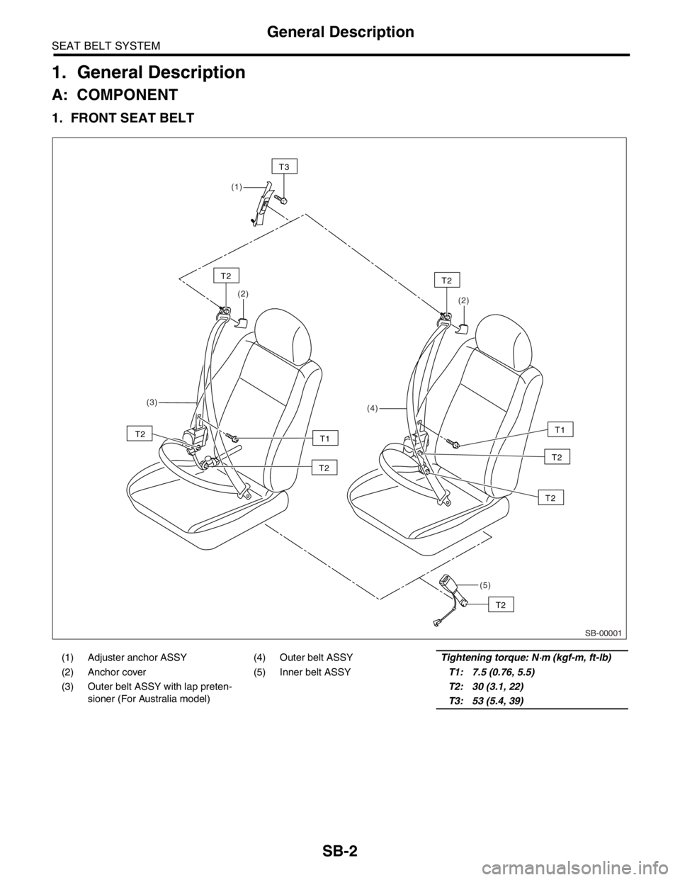
1. General Description
A: COMPONENT
1. FRONT SEAT BELT
(1) Adjuster anchor ASSY (4) Outer belt ASSYTightening torque: N⋅m (kgf-m, ft-lb)
(2) Anchor cover (5) Inner belt ASSYT1: 7.5 (0.76, 5.5)
(3) Outer belt ASSY with lap preten-
sioner (For Australia model)T2: 30 (3.1, 22)
T3: 53 (5.4, 39)
SB-00001
(2)
(3)
(4)(2)
(5) (1)
T2
T3
T2
T2
T2T2
T1
T2
T2
T1
Page 237 of 2870
SB-3
SEAT BELT SYSTEM
General Description
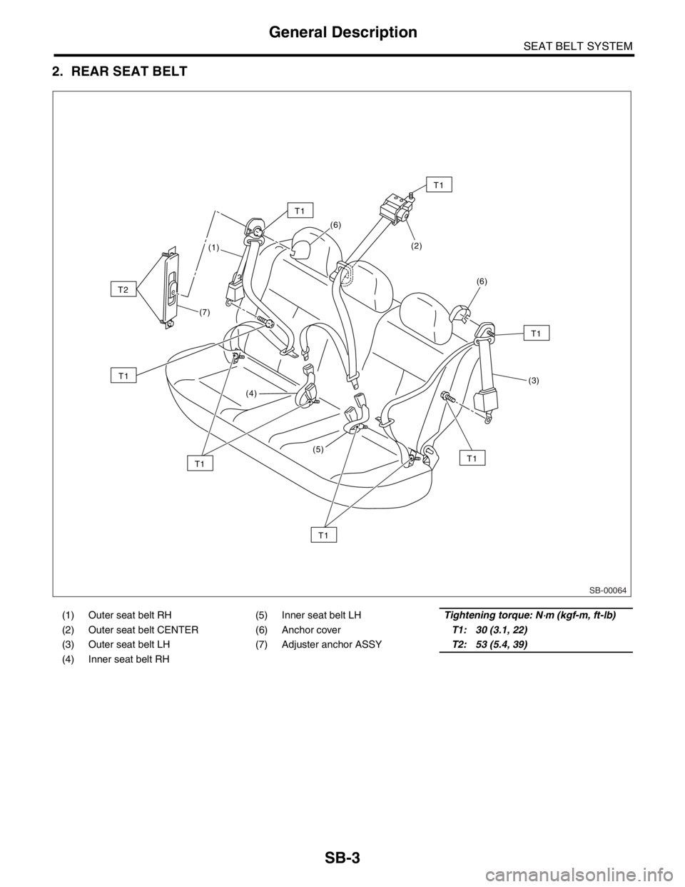
2. REAR SEAT BELT
(1) Outer seat belt RH (5) Inner seat belt LHTightening torque: N⋅m (kgf-m, ft-lb)
(2) Outer seat belt CENTER (6) Anchor coverT1: 30 (3.1, 22)
(3) Outer seat belt LH (7) Adjuster anchor ASSYT2: 53 (5.4, 39)
(4) Inner seat belt RH
SB-00064
T1
T1
T1
T1
T2
T1
T1
(1)
(7)
(4)
(5)(6)
(2)
(6)
(3)
T1
Page 238 of 2870

SB-4
SEAT BELT SYSTEM
General Description
B: CAUTION
Before starting, turn the ignition switch to OFF,
disconnect the battery ground cable and wait for 20
seconds or more.
The pretension system has a backup power source.
The pretensioner might deploy if you do not wait for 20
seconds or more before starting work.
Do not drop or apply any impact to the preten-
sioner.
If oil, grease, or water gets on the pretensioner,
wipe it off immediately with a dry cloth.
Do not expose the pretensioner to high tempera-
ture or flame.
Do not allow current to flow through or voltage to
reach the pretensioner. Do not use a circuit tester
to check resistance of the pretensioner.
Do not disassemble or attempt to repair the pre-
tensioner. If it is dented, cracked, or deformed, re-
place it with a new one.
Do not use the airbag or pretensioner parts from
other vehicles. Always replace parts with new
parts.
When handling a seat belt with a deployed pre-
tensioner, wear gloves and goggles. Wash your
hands afterwards.
Do not re-use a seat belt with a deployed preten-
sioner again.
Be sure to deploy pretensioner before disposal.
If the material gets in your eyes or on your skin
during deployment, wash it away with clean water,
and then consult a doctor.
Page 239 of 2870
SB-5
SEAT BELT SYSTEM
General Description
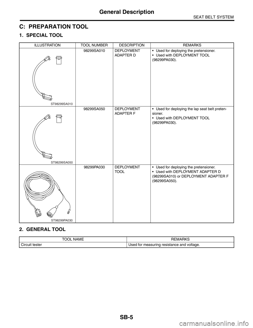
C: PREPARATION TOOL
1. SPECIAL TOOL
2. GENERAL TOOL
ILLUSTRATION TOOL NUMBER DESCRIPTION REMARKS
98299SA010 DEPLOYMENT
ADAPTER D Used for deploying the pretensioner.
Used with DEPLOYMENT TOOL
(98299PA030).
98299SA050 DEPLOYMENT
ADAPTER F Used for deploying the lap seat belt preten-
sioner.
Used with DEPLOYMENT TOOL
(98299PA030).
98299PA030 DEPLOYMENT
TOOL Used for deploying the pretensioner.
Used with DEPLOYMENT ADAPTER D
(98299SA010) or DEPLOYMENT ADAPTER F
(98299SA050).
TOOL NAME REMARKS
Circuit tester Used for measuring resistance and voltage.
ST98299SA010
ST98299SA050
ST98299PA030
Page 240 of 2870

SB-6
SEAT BELT SYSTEM
Inspection Locations After a Collision
2. Inspection Locations After a
Collision
A: INSPECTION
Check for the following, and then replace with new
parts if necessary.
Center pillar lower garnish is discolored or cracked.
Wiring harness and/or connector is damaged.