SUBARU FORESTER 2004 Service Repair Manual
Manufacturer: SUBARU, Model Year: 2004, Model line: FORESTER, Model: SUBARU FORESTER 2004Pages: 2870, PDF Size: 38.67 MB
Page 241 of 2870

SB-7
SEAT BELT SYSTEM
Seat Belt Warning System
3. Seat Belt Warning System
A: WIRING DIAGRAM
B: INSPECTION
TROUBLE SYMPTOM:
Seat belt warning light does not come on or go off.
Buzzer does not beep.
Step Check Yes No
1 CHECK HARNESS BETWEEN SEAT BELT
TIMER MODULE AND CHASSIS GROUND.
1) Turn the ignition switch to OFF.
2) Disconnect the connector from seat belt
timer module.
3) Measure the resistance between seat belt
timer module harness connector and chassis
ground.
Connector & terminal
(B44) No. 3 — Chassis ground:Is the resistance less than 1
Ω?Go to step 2.Repair the open
circuit of harness
between seat belt
timer module and
chassis ground.
2 CHECK POWER SUPPLY OF SEAT BELT
TIMER MODULE.
1) Turn the ignition switch to ON.
2) Measure the voltage between seat belt
timer module connector and chassis ground.
Connector & terminal
(B44) No. 9 (+) — Chassis ground (–):Is the voltage more than 10 V? Go to step 3.Repair the open
harness, short cir-
cuit and poor con-
tact of connector
between seat belt
timer module and
battery.
3 CHECK HARNESS AND SEAT BELT
SWITCH.
1) Turn the ignition switch to OFF.
2) Disconnect the connector from seat belt
timer module.
3) Hold the tang plate disconnected from seat
belt buckle.
4) Measure the resistance between seat belt
timer module harness connector and chassis
ground.
Connector & terminal
(B44) No. 6 — Chassis ground:Is the resistance less than 1
Ω?Go to step 4.Repair the short
circuit of harness
between seat belt
timer module con-
nector and chassis
ground.
4 CHECK SEAT BELT SWITCH AND HAR-
NESS.
1) Turn the ignition switch to OFF.
2) Insert the tang plate into seat belt buckle.
3) Measure the resistance between seat belt
timer module connector and chassis ground.
Connector & terminal
(B44) No. 6 — Chassis ground:Is the resistance more than 1
MΩ?Go to step 7.Go to step 5.
5 CHECK HARNESS BETWEEN SEAT BELT
TIMER MODULE AND SEAT BELT SWITCH.
Measure the resistance of harness between
seat belt timer module connector and seat belt
switch.
Connector & terminal
(B44) No. 6 — (R8) No. 2:Is the resistance less than 1
Ω?Go to step 6.Repair the open
circuit of harness
and poor contact
of connector
between seat belt
timer module con-
nector and seat
belt switch.
Page 242 of 2870

SB-8
SEAT BELT SYSTEM
Seat Belt Warning System
6 CHECK HARNESS BETWEEN SEAT BELT
SWITCH AND CHASSIS GROUND.
Measure the resistance of harness between
seat belt switch and chassis ground.
Connector & terminal
(R8) No. 1 — Chassis ground:Is the resistance more than 1
MΩ?Go to step 7.Repair the open
circuit of harness
between seat belt
switch and chas-
sis ground.
7 CHECK SEAT BELT SWITCH.
1) Hold the tang plate disconnected from seat
belt buckle.
2) Measure the resistance between seat belt
switch terminals.
Te r m i n a l s
(R8) No. 1 — (R8) No. 2:Is the resistance less than 1
Ω?Go to step 8.Replace the inner
belt assembly.
8 CHECK SEAT BELT SWITCH.
1) Insert the tang plate into seat belt buckle.
2) Measure the resistance between seat belt
switch terminals.
Te r m i n a l s
(R8) No. 1 — (R8) No. 2:Is the resistance more than 1
MΩ?Go to step 9.Replace the inner
belt assembly.
9 CHECK OPERATION OF SPEEDOMETER IN
COMBINATION METER.
Check the speedometer indicates vehicle
speed correctly.Does the speedometer operate
correctly?Go to step 10.Check the speed-
ometer circuit.
10 CHECK VEHICLE MODEL.
Check the model of vehicle.Is the vehicle MT model? Go to step 11.Go to step 13.
11 CHECK HARNESS BETWEEN VEHICLE
SPEED SENSOR AND SEAT BELT TIMER
MODULE.
1) Turn the ignition switch to OFF.
2) Disconnect the connector of vehicle speed
sensor.
3) Measure the resistance between vehicle
speed sensor harness connector and seat belt
timer module connector.
Connector & terminal
(B17) No. 1 — (B44) No. 7:Is the resistance less than 10
Ω?Go to step 12.Repair the open
harness between
vehicle speed sen-
sor and seat belt
timer module.
12 CHECK HARNESS BETWEEN VEHICLE
SPEED SENSOR AND SEAT BELT TIMER
MODULE.
Measure the resistance between seat belt
timer module harness connector and chassis
ground.
Connector & terminal
(B44) No. 7 — Chassis ground:Is the resistance more than 1
MΩ?Go to step 15.Repair the short of
harness.
13 CHECK HARNESS BETWEEN TCU AND
SEAT BELT TIMER MODULE.
1) Turn the ignition switch to OFF.
2) Disconnect the connector of TCU.
3) Measure the resistance of harness
between TCU harness connector and seat belt
timer module harness connector
Connector & terminal
(B56) No. 17 — (B44) No. 7:Is the resistance less than 10
Ω?Go to step 14.Repair the open
harness between
TCU and seat belt
timer module. Step Check Yes No
Page 243 of 2870

SB-9
SEAT BELT SYSTEM
Seat Belt Warning System
14 CHECK HARNESS BETWEEN TCU AND
SEAT BELT TIMER MODULE.
Measure the resistance between seat belt
timer module harness connector and chassis
ground.
Connector & terminal
(B44) No. 7 — Chassis ground:Is the resistance less than 10
Ω?Go to step 15.Repair the short of
harness.
15 CHECK SEAT BELT TIMER MODULE OUT-
PUT SIGNAL.
1) Turn the ignition switch to ON.
2) Measure the voltage between seat belt
timer module harness connector and chassis
ground.
Connector & terminal
(B44) No. 2 (+) — Chassis ground (–):Is the voltage more than 10 V? Go to step 16.Check the wiring
harness and com-
bination meter,
and then repair or
replace them.
16 CHECK POOR CONTACT.
Check the poor contact of seat belt warning
light circuit.Is there any poor contact
occurs?Repair the poor
contact.Go to step 17.
17 CHECK SEAT BELT TIMER MODULE.
1) Connect all connectors.
2) Lift-up the vehicle and place rigid racks.
NOTE:
Raise all wheels off floor.
3) Hold the tang plate disconnected from seat
belt buckle.
4) Start the engine, and set the vehicle speed
less than 19 km/h (12 MPH)
N
OTE:
The speed difference between front and rear
wheels may light the ABS warning light, but this
indicates no malfunction. When diagnosis is fin-
ished, perform the ABS memory clearance pro-
cedure of OBD system.
Check seat belt warning light comes on.Does the seat belt warning
light come on?Go to step 18.Replace the seat
belt timer module.
18 CHECK SEAT BELT TIMER MODULE.
1) Connect all connectors.
2) Lift-up the vehicle and place rigid racks.
N
OTE:
Raise all wheels off floor.
3) Hold the tang plate disconnected from seat
belt buckle.
4) Start the engine, and set the vehicle speed
more than 25 km/h (16 MPH).
NOTE:
The speed difference between front and rear
wheels may light the ABS warning light, but this
indicates no malfunction. When diagnosis is fin-
ished, perform the ABS memory clearance pro-
cedure of OBD system.
Check seat belt warning light comes on and
buzzer beeps.Does the seat belt warning
light come on and buzzer
beep?Temporary poor
contact of connec-
tor or harness may
be the cause.
Check the poor
contact.Replace the seat
belt timer module. Step Check Yes No
Page 244 of 2870
SB-10
SEAT BELT SYSTEM
Front Seat Belt
4. Front Seat Belt
A: REMOVAL
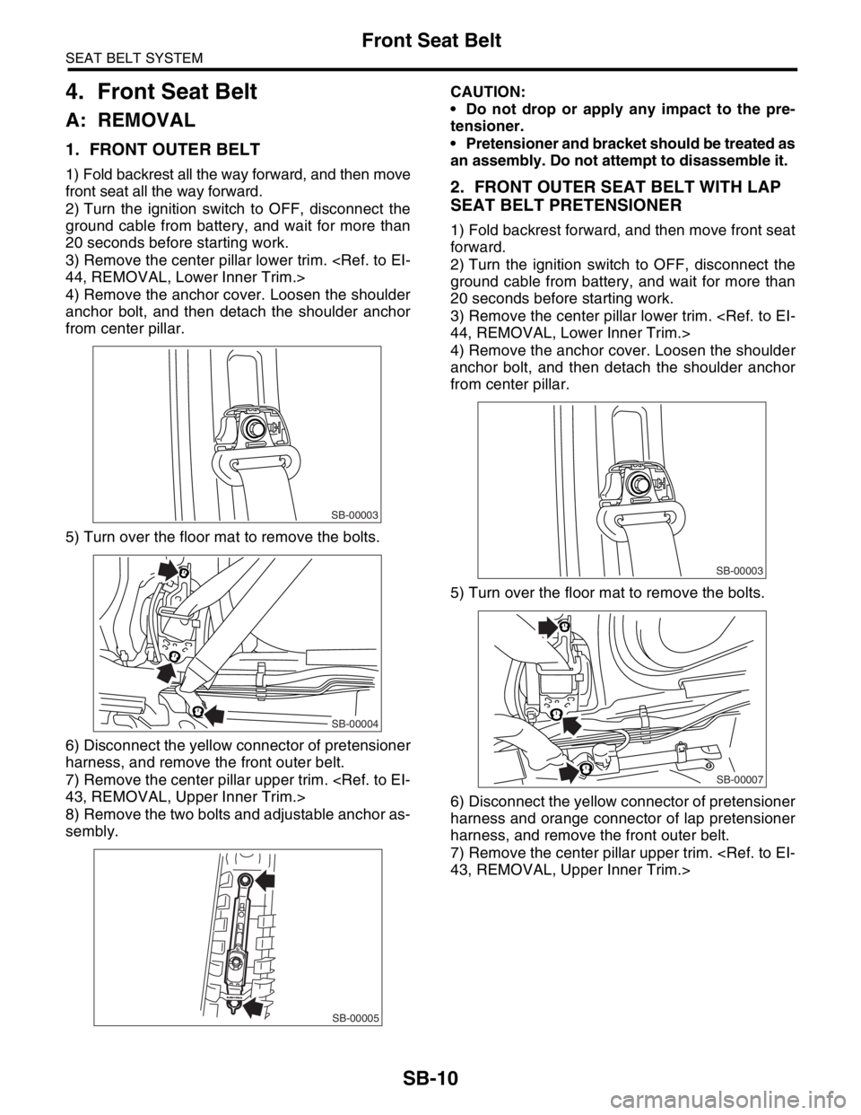
1. FRONT OUTER BELT
1) Fold backrest all the way forward, and then move
front seat all the way forward.
2) Turn the ignition switch to OFF, disconnect the
ground cable from battery, and wait for more than
20 seconds before starting work.
3) Remove the center pillar lower trim.
4) Remove the anchor cover. Loosen the shoulder
anchor bolt, and then detach the shoulder anchor
from center pillar.
5) Turn over the floor mat to remove the bolts.
6) Disconnect the yellow connector of pretensioner
harness, and remove the front outer belt.
7) Remove the center pillar upper trim.
8) Remove the two bolts and adjustable anchor as-
sembly.CAUTION:
Do not drop or apply any impact to the pre-
tensioner.
Pretensioner and bracket should be treated as
an assembly. Do not attempt to disassemble it.2. FRONT OUTER SEAT BELT WITH LAP
SEAT BELT PRETENSIONER
1) Fold backrest forward, and then move front seat
forward.
2) Turn the ignition switch to OFF, disconnect the
ground cable from battery, and wait for more than
20 seconds before starting work.
3) Remove the center pillar lower trim.
4) Remove the anchor cover. Loosen the shoulder
anchor bolt, and then detach the shoulder anchor
from center pillar.
5) Turn over the floor mat to remove the bolts.
6) Disconnect the yellow connector of pretensioner
harness and orange connector of lap pretensioner
harness, and remove the front outer belt.
7) Remove the center pillar upper trim.
SB-00003
SB-00004
SB-00005
SB-00003
SB-00007
Page 245 of 2870
SB-11
SEAT BELT SYSTEM
Front Seat Belt
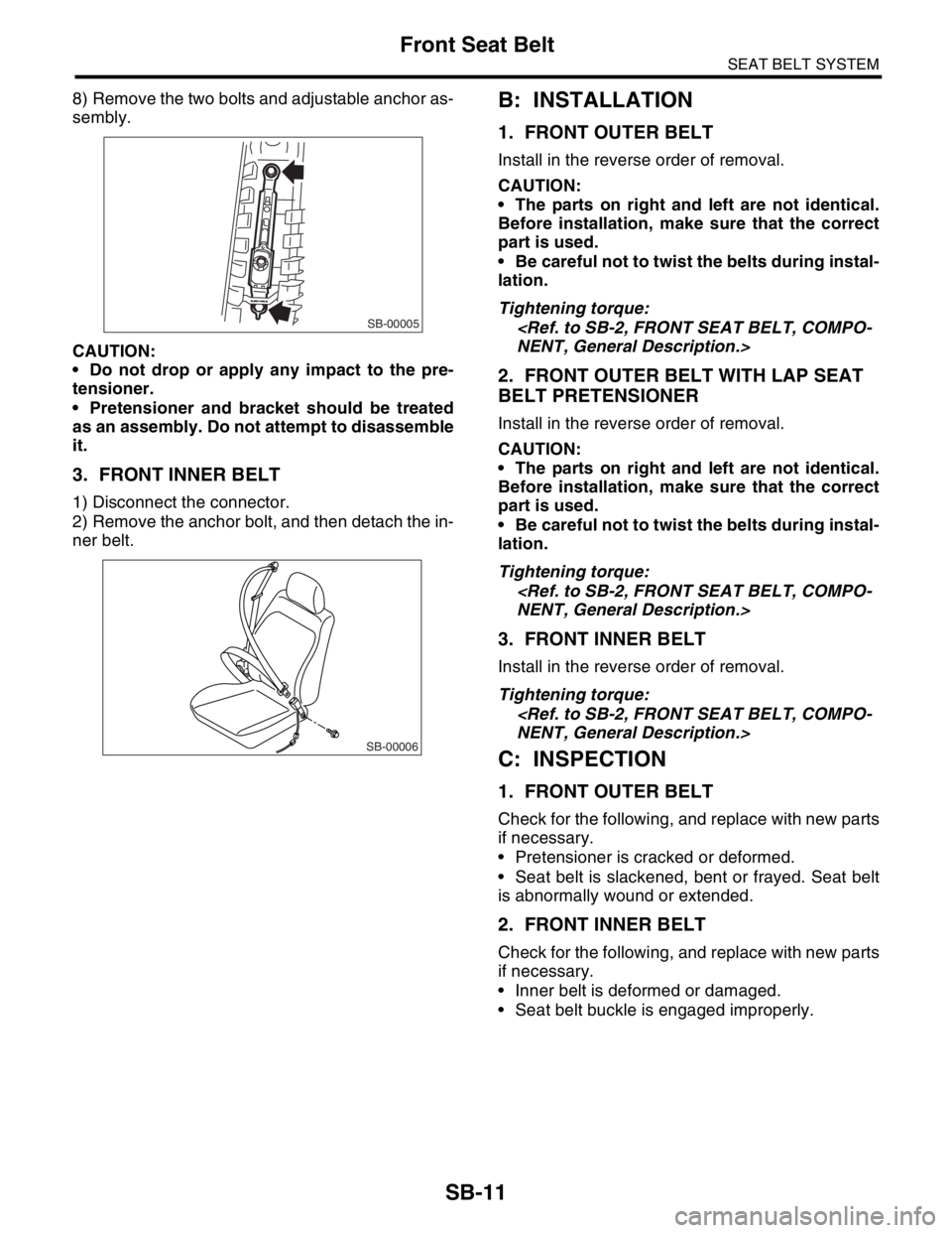
8) Remove the two bolts and adjustable anchor as-
sembly.
CAUTION:
Do not drop or apply any impact to the pre-
tensioner.
Pretensioner and bracket should be treated
as an assembly. Do not attempt to disassemble
it.
3. FRONT INNER BELT
1) Disconnect the connector.
2) Remove the anchor bolt, and then detach the in-
ner belt.
B: INSTALLATION
1. FRONT OUTER BELT
Install in the reverse order of removal.
CAUTION:
The parts on right and left are not identical.
Before installation, make sure that the correct
part is used.
Be careful not to twist the belts during instal-
lation.
Tightening torque:
2. FRONT OUTER BELT WITH LAP SEAT
BELT PRETENSIONER
Install in the reverse order of removal.
CAUTION:
The parts on right and left are not identical.
Before installation, make sure that the correct
part is used.
Be careful not to twist the belts during instal-
lation.
Tightening torque:
3. FRONT INNER BELT
Install in the reverse order of removal.
Tightening torque:
C: INSPECTION
1. FRONT OUTER BELT
Check for the following, and replace with new parts
if necessary.
Pretensioner is cracked or deformed.
Seat belt is slackened, bent or frayed. Seat belt
is abnormally wound or extended.
2. FRONT INNER BELT
Check for the following, and replace with new parts
if necessary.
Inner belt is deformed or damaged.
Seat belt buckle is engaged improperly.
SB-00005
SB-00006
Page 246 of 2870
SB-12
SEAT BELT SYSTEM
Rear Seat Belt
5. Rear Seat Belt
A: REMOVAL
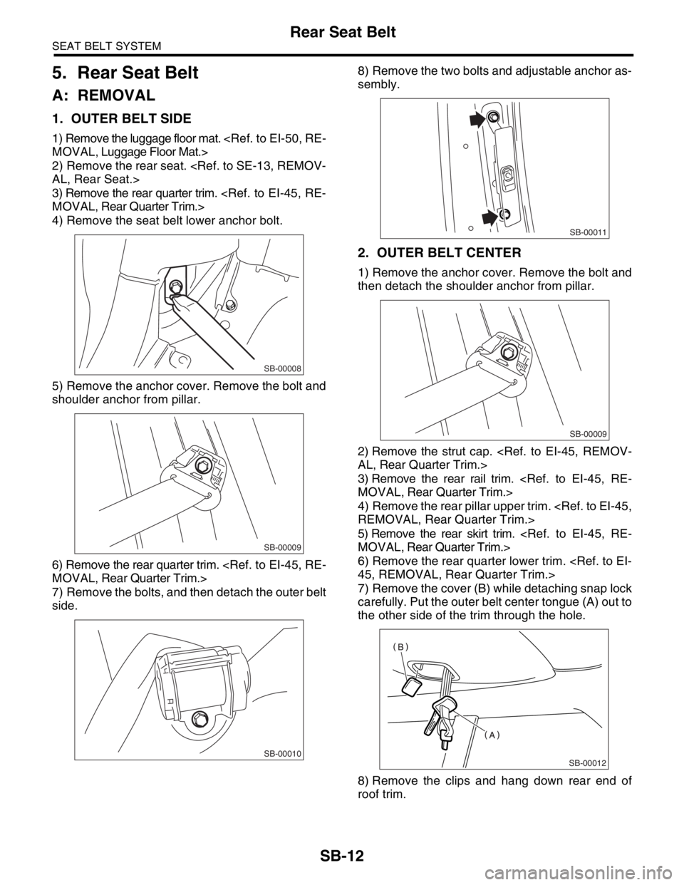
1. OUTER BELT SIDE
1) Remove the luggage floor mat.
2) Remove the rear seat.
3) Remove the rear quarter trim.
4) Remove the seat belt lower anchor bolt.
5) Remove the anchor cover. Remove the bolt and
shoulder anchor from pillar.
6) Remove the rear quarter trim.
7) Remove the bolts, and then detach the outer belt
side.8) Remove the two bolts and adjustable anchor as-
sembly.
2. OUTER BELT CENTER
1) Remove the anchor cover. Remove the bolt and
then detach the shoulder anchor from pillar.
2) Remove the strut cap.
3) Remove the rear rail trim.
4) Remove the rear pillar upper trim.
5) Remove the rear skirt trim.
6) Remove the rear quarter lower trim.
7) Remove the cover (B) while detaching snap lock
carefully. Put the outer belt center tongue (A) out to
the other side of the trim through the hole.
8) Remove the clips and hang down rear end of
roof trim.
SB-00008
SB-00009
SB-00010
SB-00011
SB-00009
SB-00012
Page 247 of 2870
SB-13
SEAT BELT SYSTEM
Rear Seat Belt
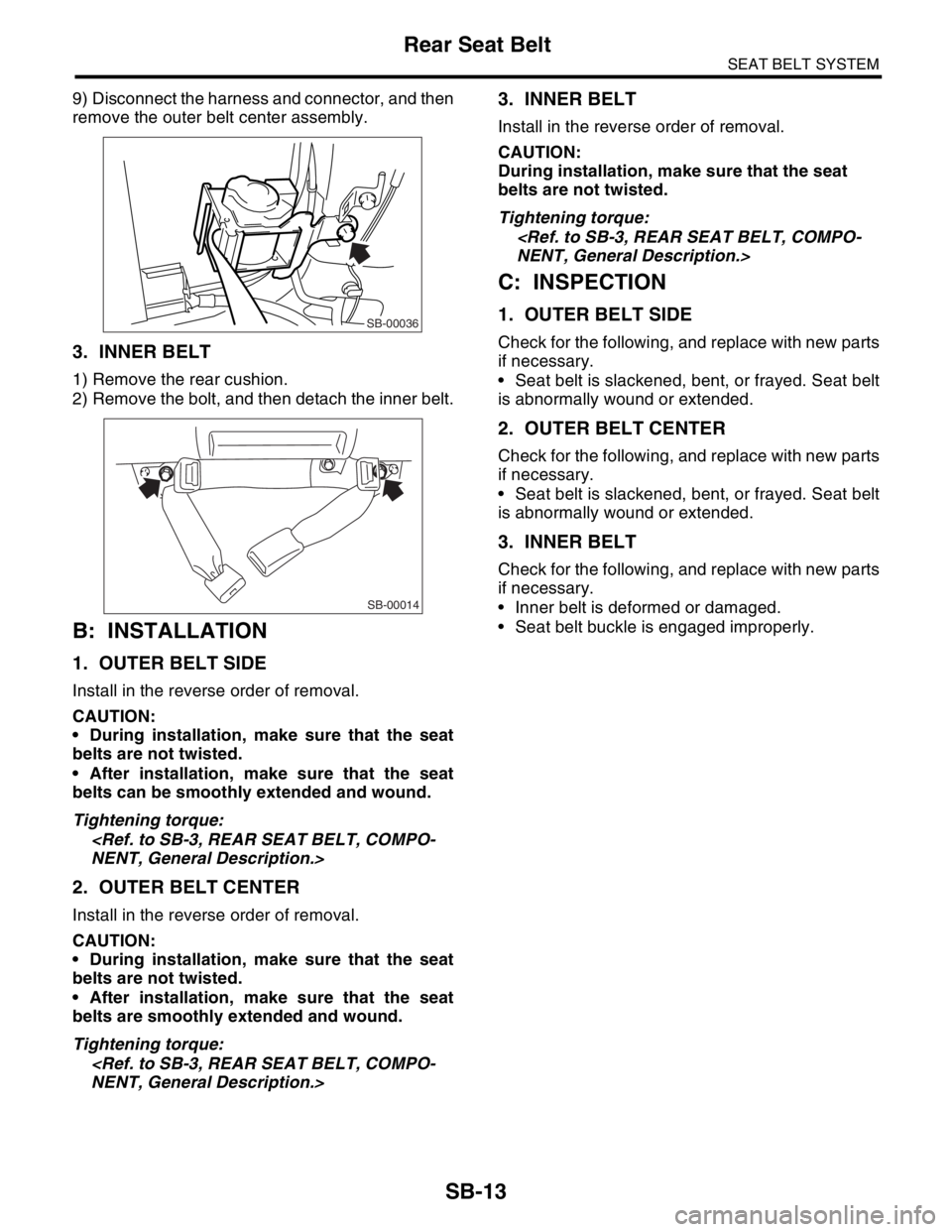
9) Disconnect the harness and connector, and then
remove the outer belt center assembly.
3. INNER BELT
1) Remove the rear cushion.
2) Remove the bolt, and then detach the inner belt.
B: INSTALLATION
1. OUTER BELT SIDE
Install in the reverse order of removal.
CAUTION:
During installation, make sure that the seat
belts are not twisted.
After installation, make sure that the seat
belts can be smoothly extended and wound.
Tightening torque:
2. OUTER BELT CENTER
Install in the reverse order of removal.
CAUTION:
During installation, make sure that the seat
belts are not twisted.
After installation, make sure that the seat
belts are smoothly extended and wound.
Tightening torque:
3. INNER BELT
Install in the reverse order of removal.
CAUTION:
During installation, make sure that the seat
belts are not twisted.
Tightening torque:
C: INSPECTION
1. OUTER BELT SIDE
Check for the following, and replace with new parts
if necessary.
Seat belt is slackened, bent, or frayed. Seat belt
is abnormally wound or extended.
2. OUTER BELT CENTER
Check for the following, and replace with new parts
if necessary.
Seat belt is slackened, bent, or frayed. Seat belt
is abnormally wound or extended.
3. INNER BELT
Check for the following, and replace with new parts
if necessary.
Inner belt is deformed or damaged.
Seat belt buckle is engaged improperly.
SB-00036
SB-00014
Page 248 of 2870
SB-14
SEAT BELT SYSTEM
Disposal of Pretensioner
6. Disposal of Pretensioner
A: CAUTION
Do not discard undeployed pretensioners, because
they may cause serious personal injury when acci-
dentally deployed.
Deployment of the pretensioners should be done
on a flat place free from any possible danger. Avoid
deploying outdoors during heavy rainy or strong
windy weather.
Do not drop or damage the pretensioner.
Because deploying the pretensioners causes a
high-explosive noise, be sure to warn people in the
area, and do not allow anyone within a 5 m (16 ft)
radius of the disposal site.
Some smoke will be emitted after deployment of
the pretensioners. Therefore, it must be deployed
in a well-ventilated area with no smoke alarms
nearby.
Wear gloves, goggles, and earplugs during this
operation. Wash your hands afterwards.
After deployment, the pretensioner is especially
hot. Leave it unattended for 40 minutes or longer,
and then discard it.
Do not let water get on the deployed pretension-
er.
Wrap the deployed pretensioner in an airtight vi-
nyl bag, and then discard it.
If circumstances do not permit pretensioner de-
ployment, contact a SUBARU dealer.
B: OPERATION
1. DEPLOYING OF PRETENSIONER WHILE
INSTALLED IN VEHICLE
1) Fold backrest all the way forward, and then
move front seat all the way forward.
2) Turn the ignition switch to OFF, disconnect the
ground cable from battery, and wait for more than
20 seconds before starting work.
3) Remove the center pillar lower trim.
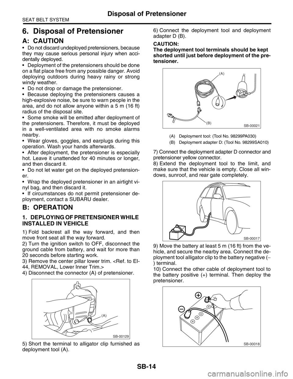
4) Disconnect the connector (A) of pretensioner.
5) Short the terminal to alligator clip furnished as
deployment tool (A).6) Connect the deployment tool and deployment
adapter D (B).
CAUTION:
The deployment tool terminals should be kept
shorted until just before deployment of the pre-
tensioner.
7) Connect the deployment adapter D connector and
pretensioner yellow connector.
8) Extend the deployment tool to the limit, and
make sure that the vehicle is empty. Close all win-
dows, sunroof, and rear gate completely.
9) Move the battery at least 5 m (16 ft) from the ve-
hicle, and secure the nearby area. Connect the de-
ployment tool alligator clip to the battery negative (−
) terminal.
10) Connect the other cable of deployment tool to
the battery positive (+) terminal. Then deploy the
pretensioner.
SB-00129
(A)
(A) Deployment tool: (Tool No. 98299PA030)
(B) Deployment adapter D: (Tool No. 98299SA010)
SB-00021
(A)
(B)
SB-00017
SB-00018
Page 249 of 2870
SEAT BELT SYSTEM
Disposal of Pretensioner
CAUTION:
After deployment, pretensioner is especially
hot. Leave it unattended for 40 minutes or long-
er.
Do not let water get on the deployed preten-
sioner.
11) Perform the following steps 12) through 17) for
the vehicle with lap pretensioner.
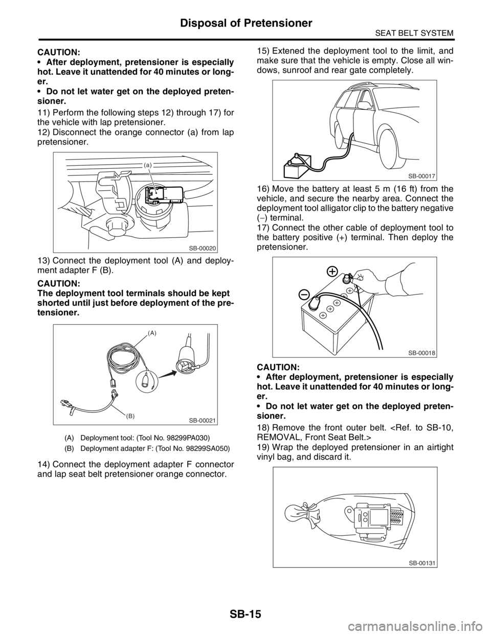
12) Disconnect the orange connector (a) from lap
pretensioner.
13) Connect the deployment tool (A) and deploy-
ment adapter F (B).
CAUTION:
The deployment tool terminals should be kept
shorted until just before deployment of the pre-
tensioner.
14) Connect the deployment adapter F connector
and lap seat belt pretensioner orange connector.15) Extened the deployment tool to the limit, and
make sure that the vehicle is empty. Close all win-
dows, sunroof and rear gate completely.
16) Move the battery at least 5 m (16 ft) from the
vehicle, and secure the nearby area. Connect the
deployment tool alligator clip to the battery negative
(
− ) terminal.
17) Connect the other cable of deployment tool to
the battery positive (+) terminal. Then deploy the
pretensioner.
CAUTION:
After deployment, pretensioner is especially
hot. Leave it unattended for 40 minutes or long-
er.
Do not let water get on the deployed preten-
sioner.
18) Remove the front outer belt.
19) Wrap the deployed pretensioner in an airtight
vinyl bag, and discard it.
(A) Deployment tool: (Tool No. 98299PA030)
(B) Deployment adapter F: (Tool No. 98299SA050)
SB-00020
(a)
SB-00021
(A)
(B)
SB-00017
SB-00018
SB-00131
SB-15
Page 250 of 2870
SB-16
SEAT BELT SYSTEM
Disposal of Pretensioner
2. DEPLOYING OF RETRACTOR PRETEN-
SIONER AFTER REMOVAL FROM VEHICLE
1) Fold backrest all the way forward, then move
front seat all the way forward.
2) Turn the ignition switch to OFF, disconnect the
ground cable from battery, and wait for more than
20 seconds before starting work.
3) Remove the front outer belt.
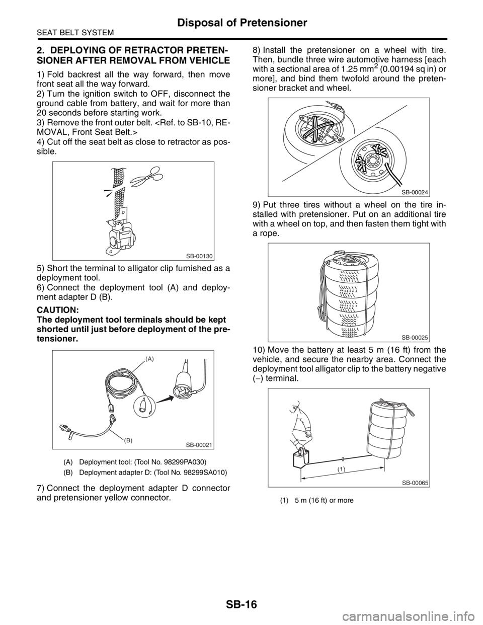
4) Cut off the seat belt as close to retractor as pos-
sible.
5) Short the terminal to alligator clip furnished as a
deployment tool.
6) Connect the deployment tool (A) and deploy-
ment adapter D (B).
CAUTION:
The deployment tool terminals should be kept
shorted until just before deployment of the pre-
tensioner.
7) Connect the deployment adapter D connector
and pretensioner yellow connector.8) Install the pretensioner on a wheel with tire.
Then, bundle three wire automotive harness [each
with a sectional area of 1.25 mm
2 (0.00194 sq in) or
more], and bind them twofold around the preten-
sioner bracket and wheel.
9) Put three tires without a wheel on the tire in-
stalled with pretensioner. Put on an additional tire
with a wheel on top, and then fasten them tight with
a rope.
10) Move the battery at least 5 m (16 ft) from the
vehicle, and secure the nearby area. Connect the
deployment tool alligator clip to the battery negative
(−) terminal.
(A) Deployment tool: (Tool No. 98299PA030)
(B) Deployment adapter D: (Tool No. 98299SA010)
SB-00130
SB-00021
(A)
(B)
(1) 5 m (16 ft) or more
SB-00024
SB-00025
SB-00065
(1)