SUBARU FORESTER 2004 Service Repair Manual
Manufacturer: SUBARU, Model Year: 2004, Model line: FORESTER, Model: SUBARU FORESTER 2004Pages: 2870, PDF Size: 38.67 MB
Page 2671 of 2870

4AT(H4DOTC)-95
AUTOMATIC TRANSMISSION (DIAGNOSTIC)
Diagnostic Procedure with Diagnostic Trouble Code (DTC)
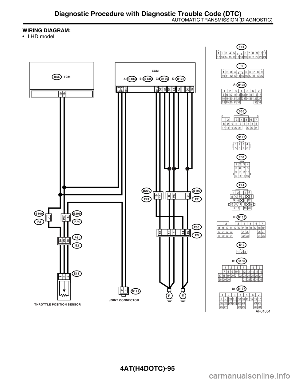
WIRING DIAGRAM:
LHD model
AT-01851
E13
B122
F60
B134B55 TCM
A:B135 B:ECMB136 C:B137 D:
E3
B100
F2
B200
F74
F61
E2
B200
F74
B100
F2F60
13 14 15 16
12 34
56 78
9
10 11 12
13161415
3
111098
20
1
3
210
19
C18
C16
C35D2D1 D7
B4B12A7 A6B1
EE
12
20
19
18
7
23
16
F61
1
234
56
78
9
1314
15
20
19 1716 10 111218
JOINT CONNECTOR
THROTTLE POSITION SENSOR
F74
34 12 89
10 11
12 13 14 15 16 17 18 19 20 21 22 23 24567
F2
1234 56789
10 11 12 13 14 15 16 17 18 19 20
B134 A:
56 7
82 1
94 310
24 22 23 25 11 12 13 14 15
26 27
2816 17
18 19 20 21
33 34 29
32 30 31
B55
12 7
8956 34
10 11 12
19 20 2113 14 15 16
17 18 22 23 24
B122
12345678
B136
56
782 1
94 310
24 22 23 2511 12 13
1415
26 27
2816
17 18 19 20 21
33 34 29
32 30
31 35
C:
B137
567
82 1
94 310
22 23 11 12 13 14 15
24 25
2616 17
18 19 20 21
27 28 29 30 31
D:
123
E13
B135 B:
567
82 1
94 310
24 22 23 2511 12 13 14 15
26 27
2816 17 18 19
20 21
29 30 31 32 33 34 35
Page 2672 of 2870

4AT(H4DOTC)-96
AUTOMATIC TRANSMISSION (DIAGNOSTIC)
Diagnostic Procedure with Diagnostic Trouble Code (DTC)
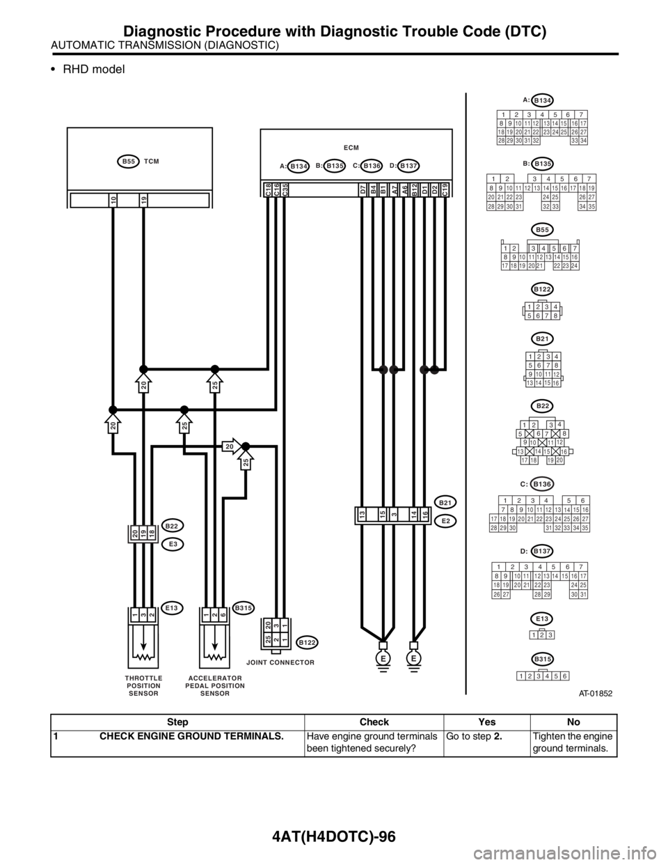
RHD model
Step Check Yes No
1 CHECK ENGINE GROUND TERMINALS.Have engine ground terminals
been tightened securely?Go to step 2.Tighten the engine
ground terminals.
AT-01852
B55
12 7
8956 34
10 11 12
19 20 2113 14 15 16
17 18 22 23 24
E13
B122
B21
B134B55 TCM
A:B135 B:B137 D: ECMB136 C:
E2B22
E3
B21
13 1415
16
12 34
56 78
9
10
11
12
13161415
3
1
3
210
19
C18
C16
C35D2D1D7
B12B4C19A6 A7B1
EE
1225
1320
20
19
18
B22
1
234
56
78
9
1314
15
20
19 1716 10 111218
JOINT CONNECTOR
THROTTLE
POSITION
SENSOR
B3151
2
6
ACCELERATOR
PEDAL POSITION
SENSOR
123
E13
20
20
20
25
25
25
B315
1
23456
B136
56
782 1
94 310
24 22 23 2511 12 13
1415
26 27
2816
17 18 19 20 21
33 34 29
32 30
31 35
C:
B137
567
82 1
94 310
22 23 11 12 13 14 15
24 25
2616 17
18 19 20 21
27 28 29 30 31
D:
B122
12345678
B135 B:
567
82 1
94 310
24 22 23 2511 12 13 14 15
26 27
2816 17 18 19
20 21
29 30 31 32 33 34 35
B134 A:
56 7
82 1
94 310
24 22 23 25 11 12 13 14 15
26 27
2816 17
18 19 20 21
33 34 29
32 30 31
Page 2673 of 2870

4AT(H4DOTC)-97
AUTOMATIC TRANSMISSION (DIAGNOSTIC)
Diagnostic Procedure with Diagnostic Trouble Code (DTC)
2 CHECK GROUND CIRCUIT OF ECM.
1) Turn the ignition switch to OFF.
2) Disconnect the connector from ECM.
3) Measure the resistance of harness
between ECM and engine ground.
Connector & terminal
(B134) No. 6 — Engine ground:
(B134) No. 7 — Engine ground:
(B135) No. 1 — Engine ground:
(B135) No. 4 — Engine ground:
(B135) No. 12 — Engine ground:
(B136) No. 19 — Engine ground:
(B137) No. 1 — Engine ground:
(B137) No. 2 — Engine ground:
(B137) No. 7 — Chassis ground:Is the resistance less than 5
Ω?Go to step 3.Repair the open cir-
cuit in harness
between ECM con-
nector and engine
grounding terminal.
3 CONFIRM MODEL.Is the vehicle 2.0 L model? Go to step 4.Go to step 12.
4 CHECK THROTTLE POSITION SENSOR.
1) Disconnect the connector from throttle
position sensor.
2) Measure the resistance between throttle
position sensor connector receptacle’s termi-
nals.
Connector & terminal
No. 1 — No. 2:Is the resistance 2.5 — 6 kΩ? Go to step 5.Replace the throt-
tle position sensor.
5 CHECK THROTTLE POSITION SENSOR.
Measure the resistance between throttle posi-
tion sensor connector receptacle’s terminals.
Connector & terminal
No. 3 — No. 2:Is the resistance 0.5 — 4.5
kΩ?Go to step 6.Replace the throt-
tle position sensor.
6 CHECK HARNESS CONNECTOR BETWEEN
TCM AND THROTTLE POSITION SENSOR.
1) Disconnect the connector from TCM.
2) Measure the resistance of harness between
TCM and throttle position sensor connector.
Connector & terminal
(B55) No. 19 — (E13) No. 3:Is the resistance less than 1
Ω?Go to step 7.Repair the open cir-
cuit in harness
between TCM and
throttle position
sensor connector,
and poor contact in
coupling connector.
7 CHECK HARNESS CONNECTOR BETWEEN
TCM AND THROTTLE POSITION SENSOR.
Measure the resistance of harness between
TCM connector and chassis ground.
Connector & terminal
(B55) No. 19 — Chassis ground:Is the resistance more than 1
MΩ?Go to step 8.Repair the short
circuit in harness
between TCM and
throttle position
sensor connector.
8 CHECK HARNESS CONNECTOR BETWEEN
ECM AND THROTTLE POSITION SENSOR.
1) Disconnect the connector from ECM.
2) Measure the resistance of harness between
throttle position sensor and chassis ground.
Connector & terminal
(E13) No. 2 — Chassis ground:Is the resistance more than 1
MΩ?Go to step 9.Repair the short
circuit in harness
between ECM and
throttle position
sensor.
9 PREPARE SUBARU SELECT MONITOR.Do you have a Subaru Select
Monitor?Go to step 11.Go to step 10. Step Check Yes No
Page 2674 of 2870

4AT(H4DOTC)-98
AUTOMATIC TRANSMISSION (DIAGNOSTIC)
Diagnostic Procedure with Diagnostic Trouble Code (DTC)
10 CHECK INPUT SIGNAL FOR TCM.
1) Connect the connectors to TCM, throttle
position sensor and ECM.
2) Turn the ignition switch to ON (engine
OFF).
3) Close the throttle completely.
4) Measure the voltage between TCM con-
nector and chassis ground.
Connector & terminal
(B55) No. 19 (+) — Chassis ground (
−):Is the voltage more than 0.2 V? Even if the POWER
indicator light was
blinking, the circuit
has returned to a
normal condition at
this time. A tempo-
rary poor contact of
the connector or
harness may be the
cause. Repair the
harness or connec-
tor in throttle posi-
tion sensor circuit.Go to step 20.
11 CHECK INPUT SIGNAL FOR TCM USING
SUBARU SELECT MONITOR.
1) Connect the connectors to TCM, throttle
position sensor and ECM.
2) Connect the Subaru Select Monitor to data
link connector.
3) Turn the ignition switch to ON (engine OFF).
4) Turn the Subaru Select Monitor switch to ON.
5) Close the throttle completely.
6) Read the data of throttle position sensor
using Subaru Select Monitor.
Throttle position sensor input signal is indi-
cated.Is the voltage more than 0.2 V? Even if the POWER
indicator light was
blinking, the circuit
has returned to a
normal condition at
this time. A tempo-
rary poor contact of
the connector or
harness may be the
cause. Repair the
harness or connec-
tor in throttle posi-
tion sensor circuit.Go to step 20.
12 CHECK ACCELERATOR PEDAL POSITION
SENSOR.
1) Disconnect the connector from accelerator
pedal position sensor.
2) Measure the resistance between accelera-
tor pedal position sensor connector recepta-
cle’s terminals.
Connector & terminal
No. 1 — No. 2:Is the resistance 0.75 — 3.15
kΩ?Go to step 13.Replace the accel-
erator pedal posi-
tion sensor.
13 CHECK ACCELERATOR PEDAL POSITION
SENSOR.
Measure the resistance between accelerator
pedal position sensor connector receptacle’s
terminals.
Connector & terminal
No. 3 — No. 2:Is the resistance 0.15 — 0.63
kΩ?Go to step 14.Replace the accel-
erator pedal posi-
tion sensor.
14 CHECK HARNESS CONNECTOR BETWEEN
TCM AND ACCELERATOR PEDAL POSI-
TION SENSOR.
1) Disconnect the connector from TCM.
2) Measure the resistance of harness
between TCM and accelerator pedal position
sensor connector.
Connector & terminal
(B55) No. 19 — (E13) No. 3:Is the resistance less than 1
Ω?Go to step 15.Repair the open cir-
cuit in harness
between TCM and
accelerator pedal
position sensor
connector, and
poor contact in cou-
pling connector.
15 CHECK HARNESS CONNECTOR BETWEEN
TCM AND ACCELERATOR PEDAL POSI-
TION SENSOR.
Measure the resistance of harness between
TCM connector and chassis ground.
Connector & terminal
(B55) No. 19 — Chassis ground:Is the resistance more than 1
MΩ?Go to step 16.Repair the short cir-
cuit in harness
between TCM and
accelerator pedal
position sensor
connector. Step Check Yes No
Page 2675 of 2870

4AT(H4DOTC)-99
AUTOMATIC TRANSMISSION (DIAGNOSTIC)
Diagnostic Procedure with Diagnostic Trouble Code (DTC)
16 CHECK HARNESS CONNECTOR BETWEEN
ECM AND ACCELERATOR PEDAL POSI-
TION SENSOR.
1) Disconnect the connector from ECM.
2) Measure the resistance of harness
between accelerator pedal position sensor
connector and chassis ground.
Connector & terminal
(E13) No. 2 — Chassis ground:Is the resistance more than 1
MΩ?Go to step 17.Repair the short
circuit in harness
between ECM and
accelerator pedal
position sensor.
17 PREPARE SUBARU SELECT MONITOR.Do you have a Subaru Select
Monitor?Go to step 19.Go to step 18.
18 CHECK INPUT SIGNAL FOR TCM.
1) Connect the connectors to TCM, accelera-
tor pedal position sensor and ECM.
2) Turn the ignition switch to ON (engine OFF).
3) Close the throttle completely.
4) Measure the voltage between TCM con-
nector and chassis ground.
Connector & terminal
(B55) No. 19 (+) — Chassis ground (
−):Is the voltage more than 0.4 V? Even if the POWER
indicator light was
blinking, the circuit
has returned to a
normal condition at
this time. A tempo-
rary poor contact of
the connector or
harness may be the
cause. Repair the
harness or connec-
tor in accelerator
pedal position sen-
sor circuit.Go to step 20.
19 CHECK INPUT SIGNAL FOR TCM USING
SUBARU SELECT MONITOR.
1) Connect the connectors to TCM, accelera-
tor pedal position sensor and ECM.
2) Connect the Subaru Select Monitor to data
link connector.
3) Turn the ignition switch to ON (engine OFF).
4) Turn the Subaru Select Monitor switch to ON.
5) Close the throttle completely.
6) Read the data of accelerator pedal position
sensor using Subaru Select Monitor.
Accelerator pedal position sensor input sig-
nal is indicated.Is the voltage more than 0.4 V? Even if the POWER
indicator light was
blinking, the circuit
has returned to a
normal condition at
this time. A tempo-
rary poor contact of
the connector or
harness may be the
cause. Repair the
harness or connec-
tor in accelerator
pedal position sen-
sor circuit.Go to step 20.
20 CHECK POOR CONTACT.Is there poor contact in sensor
circuit?Repair the poor
contact.Replace the TCM.
trol Module
(TCM).> Step Check Yes No
Page 2676 of 2870

4AT(H4DOTC)-100
AUTOMATIC TRANSMISSION (DIAGNOSTIC)
Diagnostic Procedure with Diagnostic Trouble Code (DTC)
Y: DTC P1709 THROTTLE POSITION SENSOR CIRCUIT HIGH INPUT
DTC DETECTING CONDITION:
Input signal circuit of throttle position sensor is shorted. (2.0 L model)
Input signal circuit of accelerator pedal position sensor is shorted. (2.5 L model)
TROUBLE SYMPTOM:
Shift point too high or too low.
Excessive shift shock.
Tight corner braking phenomenon.
Page 2677 of 2870

4AT(H4DOTC)-101
AUTOMATIC TRANSMISSION (DIAGNOSTIC)
Diagnostic Procedure with Diagnostic Trouble Code (DTC)
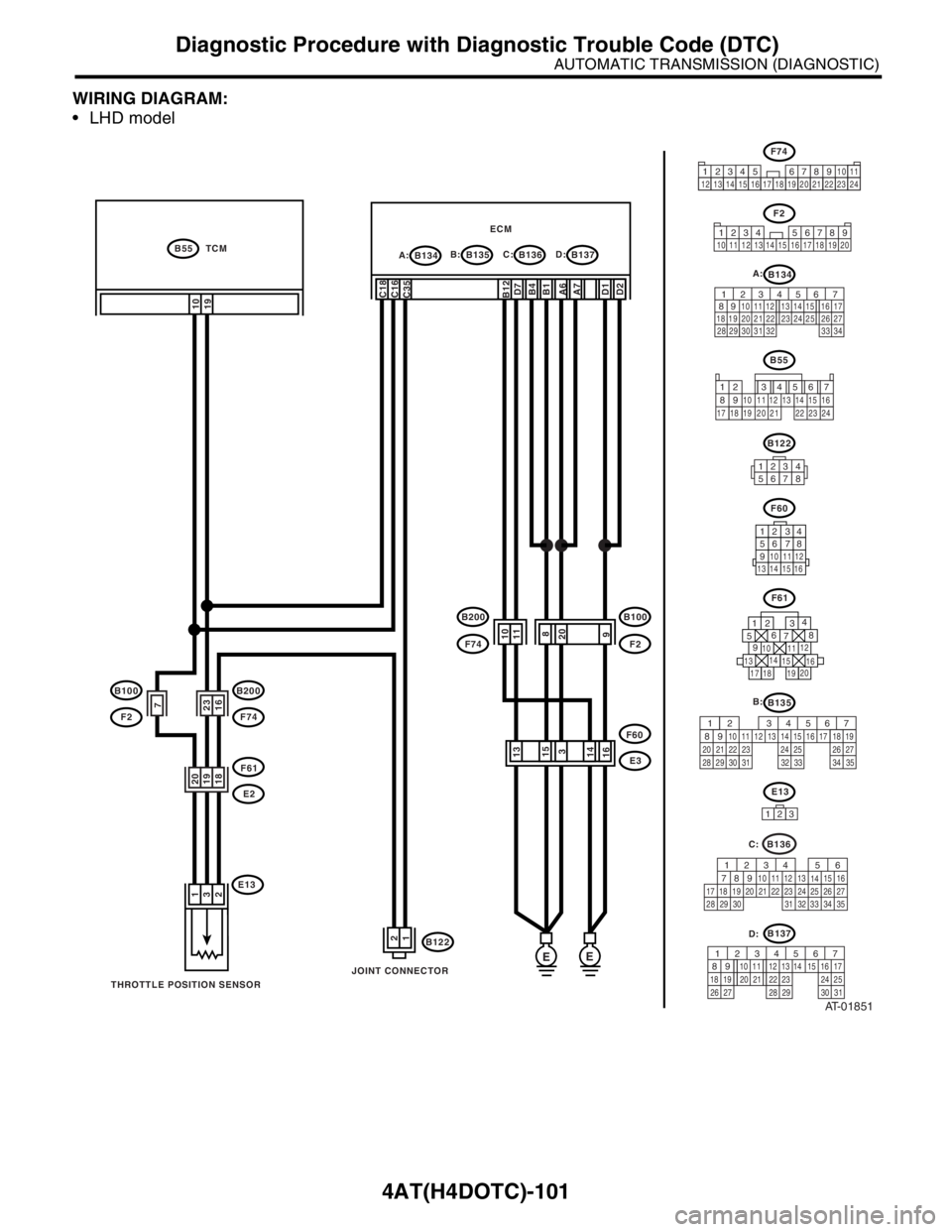
WIRING DIAGRAM:
LHD model
AT-01851
E13
B122
F60
B134B55 TCM
A:B135 B:ECMB136 C:B137 D:
E3
B100
F2
B200
F74
F61
E2
B200
F74
B100
F2F60
13 14 15 16
12 34
56 78
9
10 11 12
13161415
3
111098
20
1
3
210
19
C18
C16
C35D2D1 D7
B4B12A7 A6B1
EE
12
20
19
18
7
23
16
F61
1
234
56
78
9
1314
15
20
19 1716 10 111218
JOINT CONNECTOR
THROTTLE POSITION SENSOR
F74
34 12 89
10 11
12 13 14 15 16 17 18 19 20 21 22 23 24567
F2
1234 56789
10 11 12 13 14 15 16 17 18 19 20
B134 A:
56 7
82 1
94 310
24 22 23 25 11 12 13 14 15
26 27
2816 17
18 19 20 21
33 34 29
32 30 31
B55
12 7
8956 34
10 11 12
19 20 2113 14 15 16
17 18 22 23 24
B122
12345678
B136
56
782 1
94 310
24 22 23 2511 12 13
1415
26 27
2816
17 18 19 20 21
33 34 29
32 30
31 35
C:
B137
567
82 1
94 310
22 23 11 12 13 14 15
24 25
2616 17
18 19 20 21
27 28 29 30 31
D:
123
E13
B135 B:
567
82 1
94 310
24 22 23 2511 12 13 14 15
26 27
2816 17 18 19
20 21
29 30 31 32 33 34 35
Page 2678 of 2870

4AT(H4DOTC)-102
AUTOMATIC TRANSMISSION (DIAGNOSTIC)
Diagnostic Procedure with Diagnostic Trouble Code (DTC)
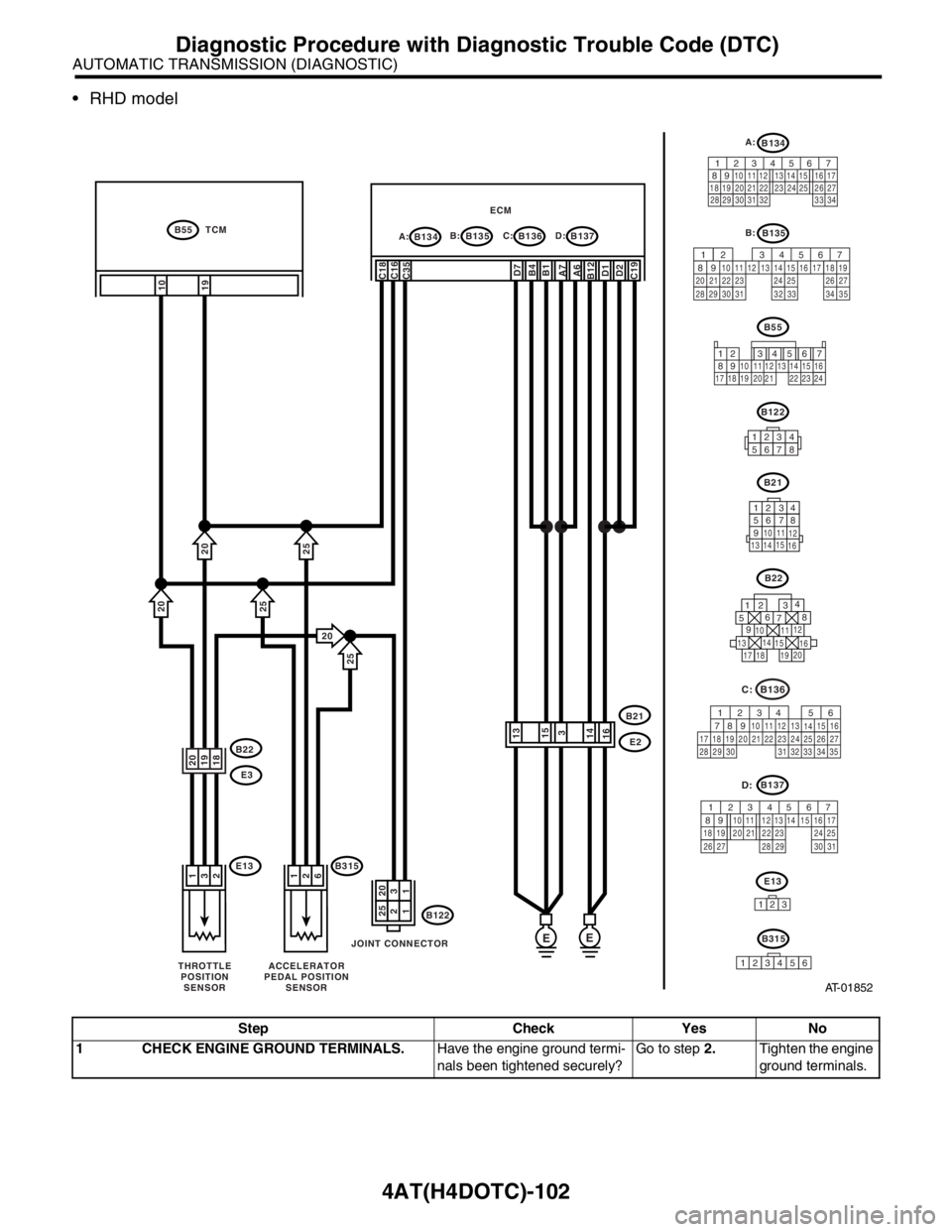
RHD model
Step Check Yes No
1 CHECK ENGINE GROUND TERMINALS.Have the engine ground termi-
nals been tightened securely?Go to step 2.Tighten the engine
ground terminals.
AT-01852
B55
12 7
8956 34
10 11 12
19 20 2113 14 15 16
17 18 22 23 24
E13
B122
B21
B134B55 TCM
A:B135 B:B137 D: ECMB136 C:
E2B22
E3
B21
13 1415
16
12 34
56 78
9
10
11
12
13161415
3
1
3
210
19
C18
C16
C35D2D1D7
B12B4C19A6 A7B1
EE
1225
1320
20
19
18
B22
1
234
56
78
9
1314
15
20
19 1716 10 111218
JOINT CONNECTOR
THROTTLE
POSITION
SENSOR
B3151
2
6
ACCELERATOR
PEDAL POSITION
SENSOR
123
E13
20
20
20
25
25
25
B315
1
23456
B136
56
782 1
94 310
24 22 23 2511 12 13
1415
26 27
2816
17 18 19 20 21
33 34 29
32 30
31 35
C:
B137
567
82 1
94 310
22 23 11 12 13 14 15
24 25
2616 17
18 19 20 21
27 28 29 30 31
D:
B122
12345678
B135 B:
567
82 1
94 310
24 22 23 2511 12 13 14 15
26 27
2816 17 18 19
20 21
29 30 31 32 33 34 35
B134 A:
56 7
82 1
94 310
24 22 23 25 11 12 13 14 15
26 27
2816 17
18 19 20 21
33 34 29
32 30 31
Page 2679 of 2870

4AT(H4DOTC)-103
AUTOMATIC TRANSMISSION (DIAGNOSTIC)
Diagnostic Procedure with Diagnostic Trouble Code (DTC)
2 CHECK GROUND CIRCUIT OF ECM.
1) Turn the ignition switch to OFF.
2) Disconnect the connector from ECM.
3) Measure the resistance of harness
between ECM and engine ground.
Connector & terminal
(B134) No. 7 — Engine ground:
(B134) No. 6 — Engine ground:
(B135) No. 1 — Engine ground:
(B135) No. 4 — Engine ground:
(B135) No. 12 — Engine ground:
(B136) No. 19 — Engine ground:
(B137) No. 1 — Engine ground:
(B137) No. 2 — Engine ground:
(B137) No. 7 — Chassis ground:Is the resistance less than 5
Ω?Go to step 3.Repair the open cir-
cuit in harness
between ECM con-
nector and engine
ground terminal.
3 CONFIRM MODEL.Is the vehicle 2.0 L model? Go to step 4.Go to step 11.
4 CHECK THROTTLE POSITION SENSOR.
1) Disconnect the connector from throttle
position sensor.
2) Measure the resistance between throttle
position sensor connector receptacle’s termi-
nals.
Connector & terminal
No. 1 — No. 2:Is the resistance 2.5 — 6 kΩ? Go to step 5.Replace the throt-
tle position sensor.
5 CHECK THROTTLE POSITION SENSOR.
Measure the resistance between throttle posi-
tion sensor connector receptacle’s terminals.
Connector & terminal
No. 2 — No. 3:Is the resistance 0.5 — 4.5
kΩ?Go to step 6.Replace the throt-
tle position sensor.
6 CHECK HARNESS CONNECTOR BETWEEN
TCM AND THROTTLE POSITION SENSOR.
1) Disconnect the connector from TCM.
2) Measure the resistance of harness
between TCM connector and chassis ground.
Connector & terminal
(B55) No. 19 — Chassis ground:Is the resistance more than 1
MΩ?Go to step 7.Repair the short
circuit in harness
between TCM and
throttle position
sensor connector.
7 CHECK HARNESS CONNECTOR BETWEEN
ECM AND THROTTLE POSITION SENSOR.
1) Disconnect the connector from ECM.
2) Measure the resistance of harness
between ECM connector and throttle position
sensor connector.
Connector & terminal
(E13) No. 2 — (B135) No. 19:Is the resistance less than 1
Ω?Go to step 8.Repair the short
circuit in harness
between ECM and
throttle position
sensor.
8 PREPARE SUBARU SELECT MONITOR.Do you have a Subaru Select
Monitor?Go to step 10.Go to step 9.
9 CHECK INPUT SIGNAL FOR TCM.
1) Connect the connectors to TCM, throttle
position sensor and ECM.
2) Turn the ignition switch to ON (engine OFF).
3) Open the throttle fully.
4) Measure the voltage between TCM con-
nector and chassis ground.
Connector & terminal
(B55) No. 19 (+) — Chassis ground (
−):Is the voltage more than 4.6 V? Go to step 18.Even if the POWER
indicator light was
blinking, the circuit
has returned to a
normal condition at
this time. A tempo-
rary poor contact of
the connector or
harness may be the
cause. Repair the
harness or connec-
tor in throttle posi-
tion sensor circuit. Step Check Yes No
Page 2680 of 2870

4AT(H4DOTC)-104
AUTOMATIC TRANSMISSION (DIAGNOSTIC)
Diagnostic Procedure with Diagnostic Trouble Code (DTC)
10 CHECK INPUT SIGNAL FOR TCM USING
SUBARU SELECT MONITOR.
1) Connect the connectors to TCM, throttle
position sensor and ECM.
2) Connect the Subaru Select Monitor to data
link connector.
3) Turn the ignition switch to ON (engine OFF).
4) Turn the Subaru Select Monitor switch to ON.
5) Open the throttle fully.
6) Read the data of throttle position sensor
using Subaru Select Monitor.
Throttle position sensor input signal is indi-
cated.Is the voltage more than 4.6 V? Go to step 18.Even if the POWER
indicator light was
blinking, the circuit
has returned to a
normal condition at
this time. A tempo-
rary poor contact of
the connector or
harness may be the
cause. Repair the
harness or connec-
tor in throttle posi-
tion sensor circuit.
11 CHECK ACCELERATOR PEDAL POSITION
SENSOR.
1) Disconnect the connector from accelerator
pedal position sensor.
2) Measure the resistance between accelera-
tor pedal position sensor connector recepta-
cle’s terminals.
Connector & terminal
No. 1 — No. 2:Is the resistance 0.75 — 3.15
kΩ?Go to step 12.Replace the accel-
erator pedal posi-
tion sensor.
12 CHECK ACCELERATOR PEDAL POSITION
SENSOR.
Measure the resistance between accelerator
pedal position sensor connector receptacle’s
terminals.
Connector & terminal
No. 2 — No. 3:Is the resistance 0.15 — 0.63
kΩ?Go to step 13.Replace the accel-
erator pedal posi-
tion sensor.
13 CHECK HARNESS CONNECTOR BETWEEN
TCM AND ACCELERATOR PEDAL POSI-
TION SENSOR.
1) Disconnect the connector from TCM.
2) Measure the resistance of harness
between TCM connector and chassis ground.
Connector & terminal
(B55) No. 19 — Chassis ground:Is the resistance more than 1
MΩ?Go to step 14.Repair the short
circuit in harness
between TCM and
accelerator pedal
position sensor
connector.
14 CHECK HARNESS CONNECTOR BETWEEN
ECM AND ACCELERATOR PEDAL POSI-
TION SENSOR.
1) Disconnect the connector from ECM.
2) Measure the resistance of harness
between ECM connector and accelerator pedal
position sensor connector.
Connector & terminal
(E13) No. 2 — (B135) No. 19:Is the resistance less than 1
Ω?Go to step 15.Repair the short
circuit in harness
between ECM and
accelerator pedal
position sensor.
15 PREPARE SUBARU SELECT MONITOR.Do you have a Subaru Select
Monitor?Go to step 17.Go to step 16. Step Check Yes No