SUBARU FORESTER 2004 Service Repair Manual
FORESTER 2004
SUBARU
SUBARU
https://www.carmanualsonline.info/img/17/57426/w960_57426-0.png
SUBARU FORESTER 2004 Service Repair Manual
Trending: battery replacement, turn signal, belt, coolant reservoir, brake sensor, height adjustment, AUX
Page 521 of 2870
EI-45
EXTERIOR/INTERIOR TRIM
Rear Quarter Trim
19.Rear Quarter Trim
A: REMOVAL
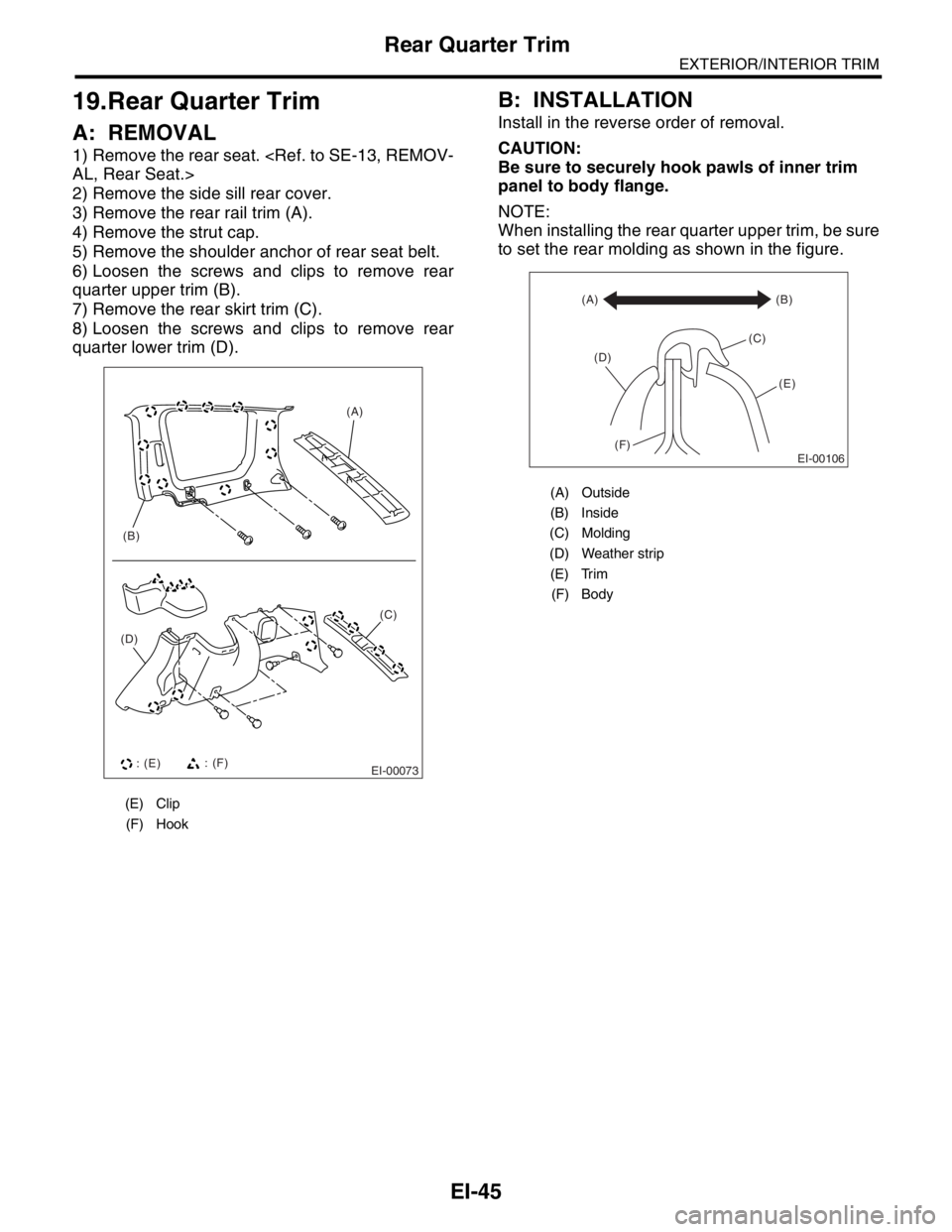
1) Remove the rear seat.
AL, Rear Seat.>
2) Remove the side sill rear cover.
3) Remove the rear rail trim (A).
4) Remove the strut cap.
5) Remove the shoulder anchor of rear seat belt.
6) Loosen the screws and clips to remove rear
quarter upper trim (B).
7) Remove the rear skirt trim (C).
8) Loosen the screws and clips to remove rear
quarter lower trim (D).
B: INSTALLATION
Install in the reverse order of removal.
CAUTION:
Be sure to securely hook pawls of inner trim
panel to body flange.
NOTE:
When installing the rear quarter upper trim, be sure
to set the rear molding as shown in the figure.
(E) Clip
(F) Hook
EI-00073
(D)(A)
(B)
(C)
: (E): (F)
(A) Outside
(B) Inside
(C) Molding
(D) Weather strip
(E) Trim
(F) Body
EI-00106
(A)
(C)(B)
(E)
(F) (D)
Page 522 of 2870
EI-46
EXTERIOR/INTERIOR TRIM
Sun Visor
20.Sun Visor
A: REMOVAL
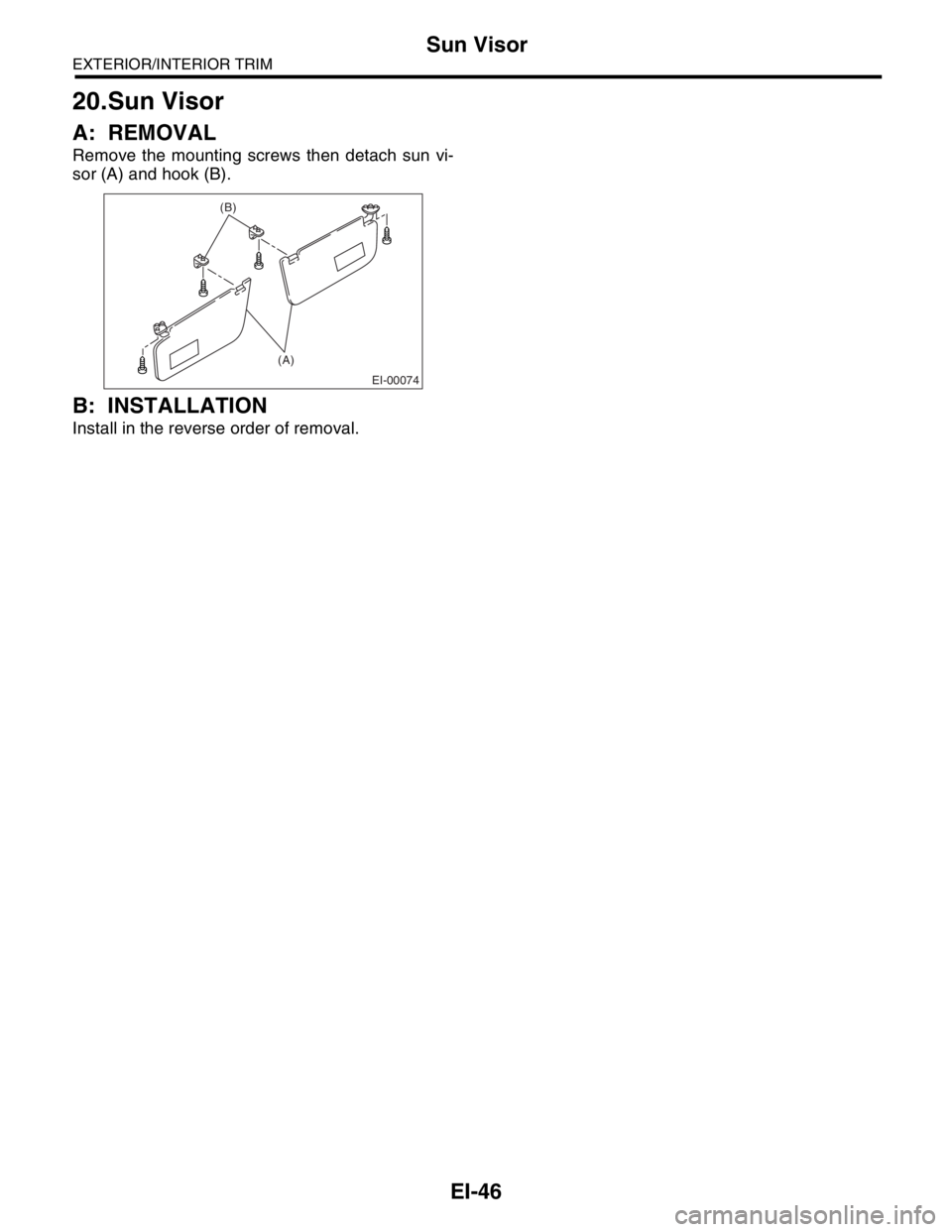
Remove the mounting screws then detach sun vi-
sor (A) and hook (B).
B: INSTALLATION
Install in the reverse order of removal.
EI-00074
(A) (B)
Page 523 of 2870
EI-47
EXTERIOR/INTERIOR TRIM
Roof Trim
21.Roof Trim
A: REMOVAL
CAUTION:
When removing the clip, use great care not to
damage the roof trim.
1) Disconnect the ground cable from battery.
2) Remove the over head console. (Sunroof model)
3) Remove the room light.
AL, Room Light.>
4) Remove the sun visor and hook or both sides.
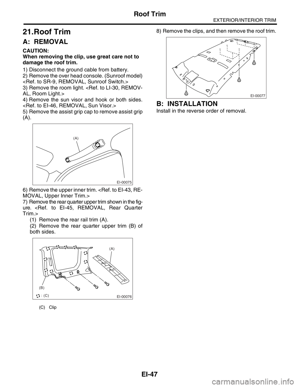
5) Remove the assist grip cap to remove assist grip
(A).
6) Remove the upper inner trim.
MOVAL, Upper Inner Trim.>
7) Remove the rear quarter upper trim shown in the fig-
ure.
Trim.>
(1) Remove the rear rail trim (A).
(2) Remove the rear quarter upper trim (B) of
both sides.8) Remove the clips, and then remove the roof trim.
B: INSTALLATION
Install in the reverse order of removal.
(C) Clip
EI-00075
(A)
EI-00076
(A)
(B)
: (C)EI-00077
Page 524 of 2870
EI-48
EXTERIOR/INTERIOR TRIM
Rear Gate Trim
22.Rear Gate Trim
A: REMOVAL
CAUTION:
Be careful not to damage the clips or their holes.
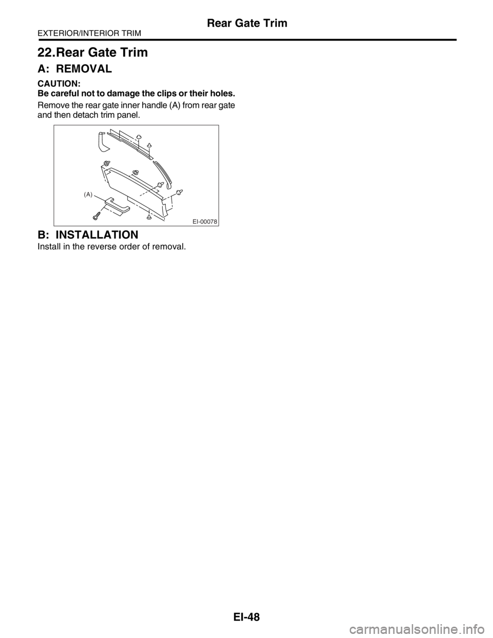
Remove the rear gate inner handle (A) from rear gate
and then detach trim panel.
B: INSTALLATION
Install in the reverse order of removal.
EI-00078
(A)
Page 525 of 2870
EI-49
EXTERIOR/INTERIOR TRIM
Floor Mat
23.Floor Mat
A: REMOVAL
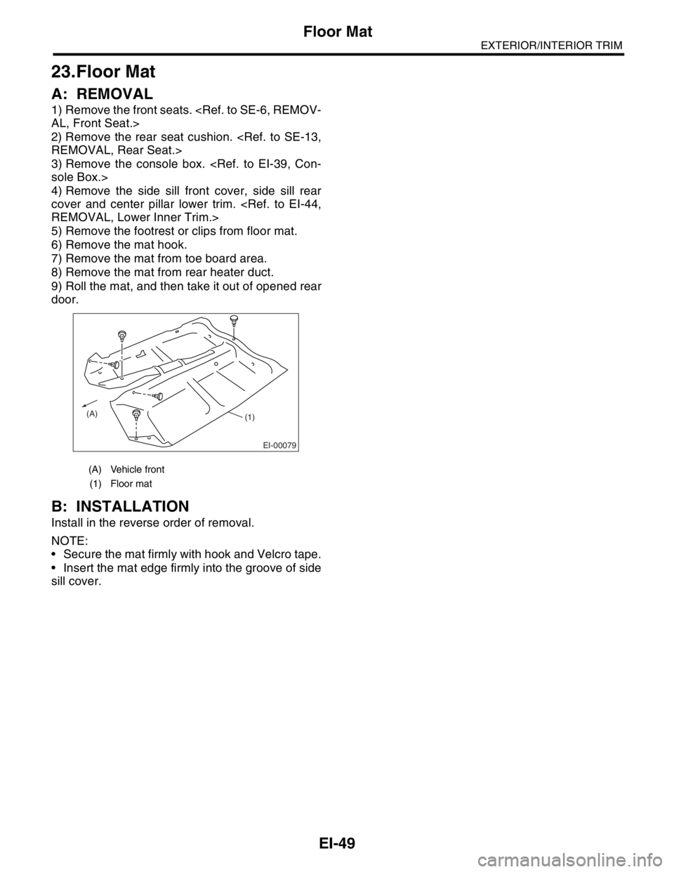
1) Remove the front seats.
AL, Front Seat.>
2) Remove the rear seat cushion.
REMOVAL, Rear Seat.>
3) Remove the console box.
sole Box.>
4) Remove the side sill front cover, side sill rear
cover and center pillar lower trim.
REMOVAL, Lower Inner Trim.>
5) Remove the footrest or clips from floor mat.
6) Remove the mat hook.
7) Remove the mat from toe board area.
8) Remove the mat from rear heater duct.
9) Roll the mat, and then take it out of opened rear
door.
B: INSTALLATION
Install in the reverse order of removal.
NOTE:
Secure the mat firmly with hook and Velcro tape.
Insert the mat edge firmly into the groove of side
sill cover.
(A) Vehicle front
(1) Floor mat
EI-00079
(A)(1)
Page 526 of 2870
EI-50
EXTERIOR/INTERIOR TRIM
Luggage Floor Mat
24.Luggage Floor Mat
A: REMOVAL
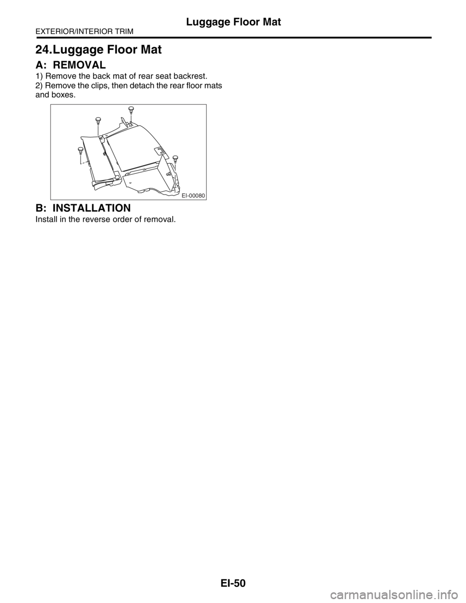
1) Remove the back mat of rear seat backrest.
2) Remove the clips, then detach the rear floor mats
and boxes.
B: INSTALLATION
Install in the reverse order of removal.
EI-00080
Page 527 of 2870
EI-51
EXTERIOR/INTERIOR TRIM
Instrument Panel Center Compartment
25.Instrument Panel Center
Compartment
A: REMOVAL
1) Disconnect the ground cable from battery.
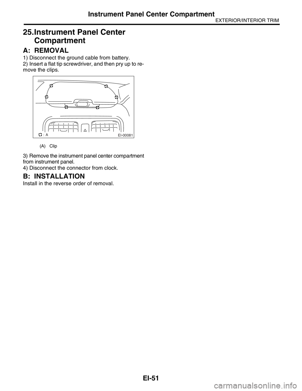
2) Insert a flat tip screwdriver, and then pry up to re-
move the clips.
3) Remove the instrument panel center compartment
from instrument panel.
4) Disconnect the connector from clock.
B: INSTALLATION
Install in the reverse order of removal.
(A) Clip
EI-00081: A
Page 528 of 2870
EI-52
EXTERIOR/INTERIOR TRIM
Heat Shield Cover
26.Heat Shield Cover
A: REMOVAL
1. FRONT HEAT SHIELD COVER
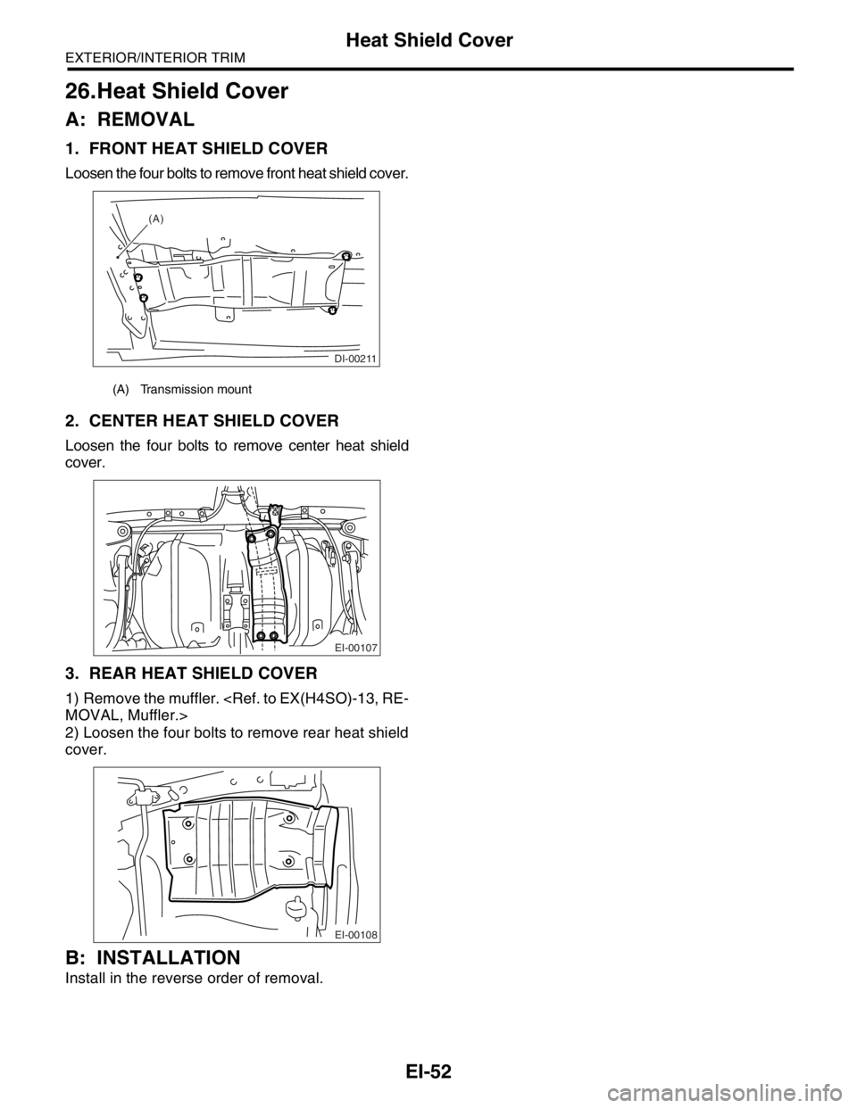
Loosen the four bolts to remove front heat shield cover.
2. CENTER HEAT SHIELD COVER
Loosen the four bolts to remove center heat shield
cover.
3. REAR HEAT SHIELD COVER
1) Remove the muffler.
MOVAL, Muffler.>
2) Loosen the four bolts to remove rear heat shield
cover.
B: INSTALLATION
Install in the reverse order of removal.
(A) Transmission mount
DI-00211
(A)
EI-00107
EI-00108
Page 529 of 2870
FUJI HEAVY INDUSTRIES LTD. G8080GE7
2004 FORESTER SERVICE MANUAL QUICK REFERENCE INDEX
BODY SECTION
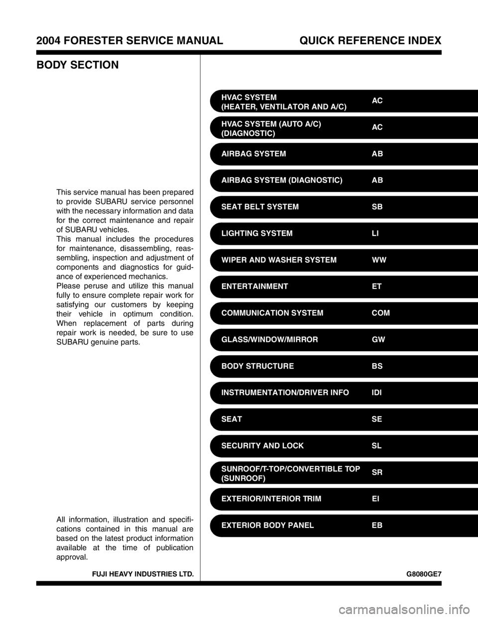
This service manual has been prepared
to provide SUBARU service personnel
with the necessary information and data
for the correct maintenance and repair
of SUBARU vehicles.
This manual includes the procedures
for maintenance, disassembling, reas-
sembling, inspection and adjustment of
components and diagnostics for guid-
ance of experienced mechanics.
Please peruse and utilize this manual
fully to ensure complete repair work for
satisfying our customers by keeping
their vehicle in optimum condition.
When replacement of parts during
repair work is needed, be sure to use
SUBARU genuine parts.
All information, illustration and specifi-
cations contained in this manual are
based on the latest product information
available at the time of publication
approval.HVAC SYSTEM
(HEATER, VENTILATOR AND A/C)AC
HVAC SYSTEM (AUTO A/C)
(DIAGNOSTIC)AC
AIRBAG SYSTEM AB
AIRBAG SYSTEM (DIAGNOSTIC) AB
SEAT BELT SYSTEM SB
LIGHTING SYSTEM LI
WIPER AND WASHER SYSTEM WW
ENTERTAINMENT ET
COMMUNICATION SYSTEM COM
GLASS/WINDOW/MIRROR GW
BODY STRUCTURE BS
INSTRUMENTATION/DRIVER INFO IDI
SEAT SE
SECURITY AND LOCK SL
SUNROOF/T-TOP/CONVERTIBLE TOP
(SUNROOF)SR
EXTERIOR/INTERIOR TRIM EI
EXTERIOR BODY PANEL EB
Page 530 of 2870
2004 FORESTER SERVICE MANUAL QUICK REFERENCE INDEX
BODY SECTION
G8080GE7
CRUISE CONTROL SYSTEM CC
CRUISE CONTROL SYSTEM
(DIAGNOSTIC)CC(H4SO)
CRUISE CONTROL SYSTEM
(DIAGNOSTIC)CC(H4DOTC)
CRUISE CONTROL SYSTEM
(DIAGNOSTIC)CC(H4DOTC 2.5)
IMMOBILIZER (DIAGNOSTIC) IM
Trending: maintenance, child seat, remote control, dead battery, glove box, radiator cap, power steering pump
