SUBARU FORESTER 2004 Service Repair Manual
Manufacturer: SUBARU, Model Year: 2004, Model line: FORESTER, Model: SUBARU FORESTER 2004Pages: 2870, PDF Size: 38.67 MB
Page 561 of 2870
CC-9
CRUISE CONTROL SYSTEM
Cruise Control Command Switch
5. Cruise Control Command
Switch
A: REMOVAL
WARNING:
Before servicing, be sure to read the notes in
the AB section for proper handling of the driv-
er’s airbag module.
1) Set the front wheels in straight ahead position.
2) Turn the ignition switch to OFF.
3) Disconnect the ground cable from battery and
wait for at least 20 seconds before starting work.
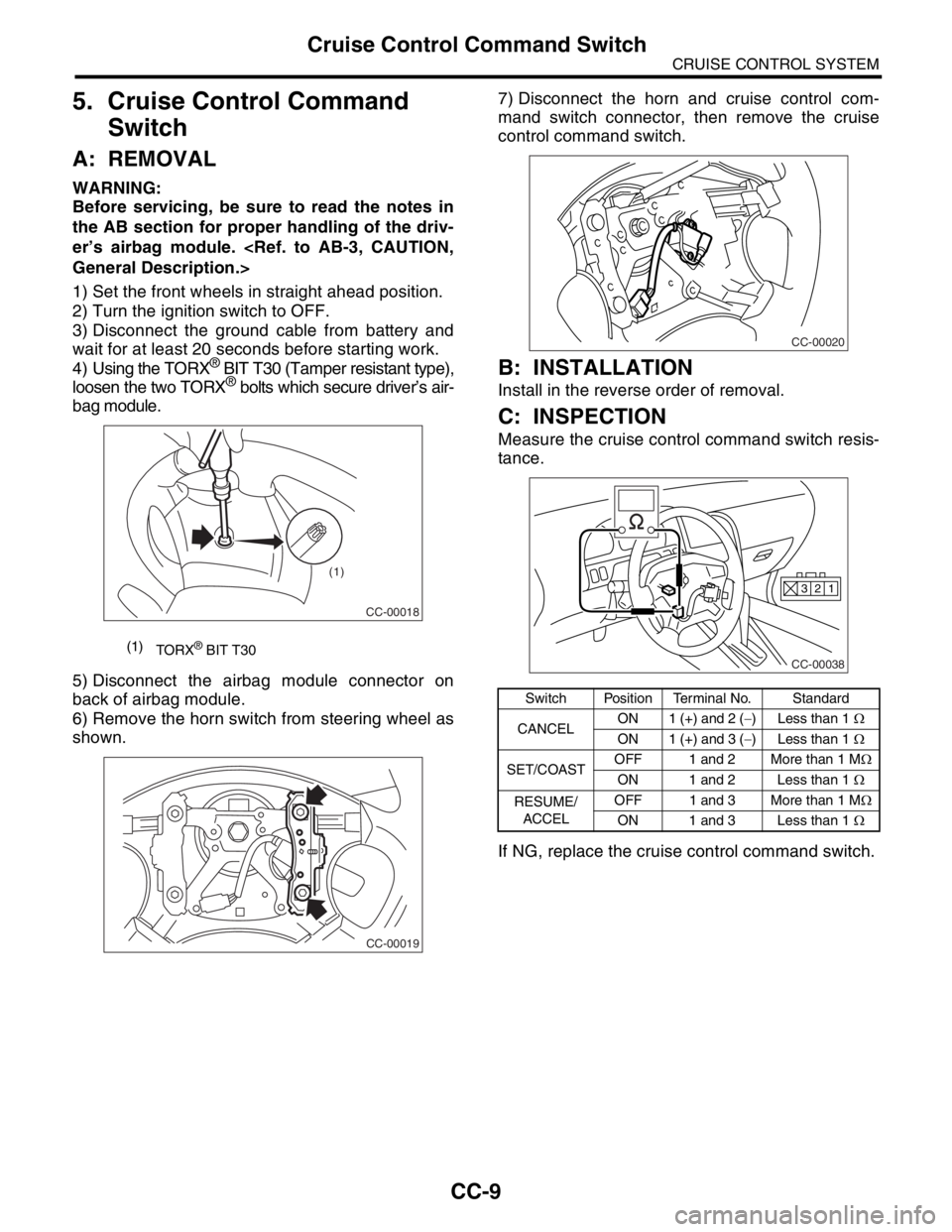
4) Using the TORX
® BIT T30 (Tamper resistant type),
loosen the two TORX® bolts which secure driver’s air-
bag module.
5) Disconnect the airbag module connector on
back of airbag module.
6) Remove the horn switch from steering wheel as
shown.7) Disconnect the horn and cruise control com-
mand switch connector, then remove the cruise
control command switch.
B: INSTALLATION
Install in the reverse order of removal.
C: INSPECTION
Measure the cruise control command switch resis-
tance.
If NG, replace the cruise control command switch.
(1)
TORX® BIT T30
CC-00018
(1)
CC-00019
Switch Position Terminal No. Standard
CANCELON 1 (+) and 2 (−) Less than 1 Ω
ON 1 (+) and 3 (−) Less than 1 Ω
SET/COASTOFF 1 and 2 More than 1 MΩ
ON 1 and 2 Less than 1 Ω
RESUME/
ACCELOFF 1 and 3 More than 1 MΩ
ON 1 and 3 Less than 1 Ω
CC-00020
CC-00038
1 2 3
Page 562 of 2870
CC-10
CRUISE CONTROL SYSTEM
Stop and Brake Switch
6. Stop and Brake Switch
A: REMOVAL
1) Disconnect the ground cable from battery.
2) Disconnect the connector from stop and brake
switch, and then remove the switch.
B: INSTALLATION
Install in the reverse order of removal.
C: INSPECTION
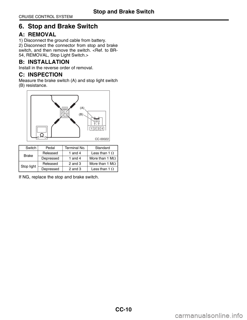
Measure the brake switch (A) and stop light switch
(B) resistance.
If NG, replace the stop and brake switch.
Switch Pedal Terminal No. Standard
BrakeReleased 1 and 4 Less than 1 Ω
Depressed 1 and 4 More than 1 MΩ
Stop lightReleased 2 and 3 More than 1 MΩ
Depressed 2 and 3 Less than 1 Ω
CC-00022
1234
(A)
(B)
3 2 14
Page 563 of 2870
CC-11
CRUISE CONTROL SYSTEM
Clutch Switch
7. Clutch Switch
A: REMOVAL
1) Disconnect the ground cable from battery.
2) Disconnect the connector from clutch switch,
and then remove the switch.
B: INSTALLATION
Install in the reverse order of removal.
C: INSPECTION
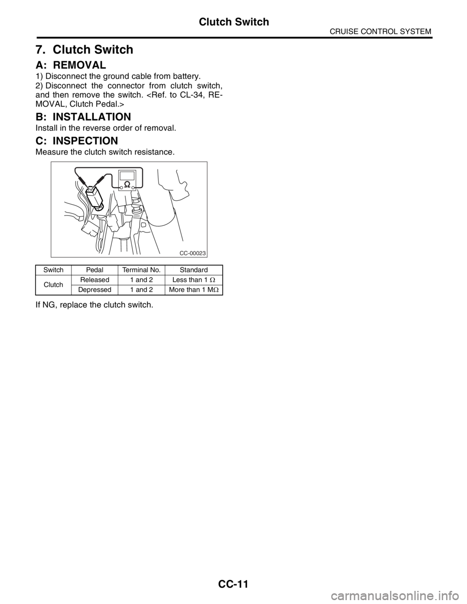
Measure the clutch switch resistance.
If NG, replace the clutch switch.
Switch Pedal Terminal No. Standard
ClutchReleased 1 and 2 Less than 1 Ω
Depressed 1 and 2 More than 1 MΩ
CC-00023
Page 564 of 2870
CC-12
CRUISE CONTROL SYSTEM
Inhibitor Switch (AT model)
8. Inhibitor Switch (AT model)
A: REMOVAL
1) Disconnect the ground cable from battery.
2) Disconnect the connector from inhibitor switch,
and then remove the switch.
B: INSTALLATION
Install in the reverse order of removal.
C: INSPECTION
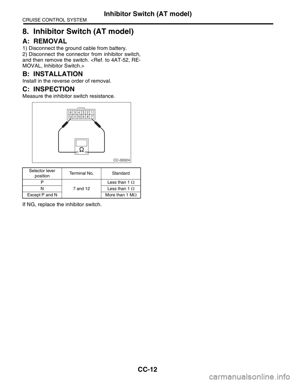
Measure the inhibitor switch resistance.
If NG, replace the inhibitor switch.
Selector lever
positionTerminal No. Standard
P
7 and 12Less than 1 Ω
N Less than 1 Ω
Except P and N More than 1 MΩ
CC-00024
123456789101112
Page 565 of 2870
CC-13
CRUISE CONTROL SYSTEM
Neutral Position Switch (MT model)
9. Neutral Position Switch (MT
model)
A: REMOVAL
1) Disconnect the ground cable from battery.
2) Disconnect the connector from neutral position
switch, and then remove the switch.
SWITCH, REMOVAL, Switches and Harness.>
B: INSTALLATION
Install in the reverse order of removal.
C: INSPECTION
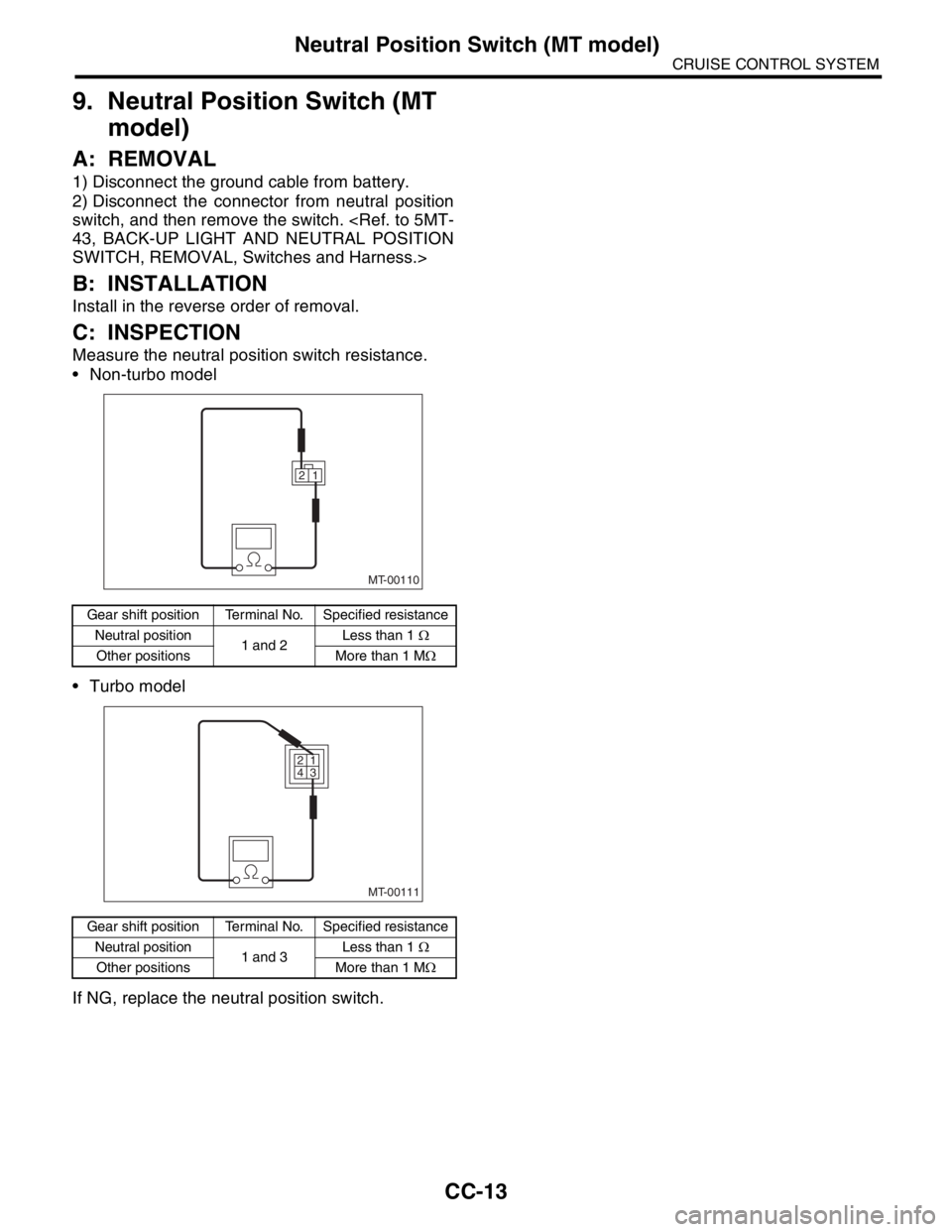
Measure the neutral position switch resistance.
Non-turbo model
Turbo model
If NG, replace the neutral position switch.
Gear shift position Terminal No. Specified resistance
Neutral position
1 and 2Less than 1 Ω
Other positions More than 1 MΩ
Gear shift position Terminal No. Specified resistance
Neutral position
1 and 3Less than 1 Ω
Other positions More than 1 MΩ
MT-00110
1 2
MT-00111
1 2
3 4
Page 566 of 2870

CC-14
CRUISE CONTROL SYSTEM
Neutral Position Switch (MT model)
Page 567 of 2870
FUJI HEAVY INDUSTRIES LTD. G8080GE7
2004 FORESTER SERVICE MANUAL QUICK REFERENCE INDEX
BODY SECTION
This service manual has been prepared
to provide SUBARU service personnel
with the necessary information and data
for the correct maintenance and repair
of SUBARU vehicles.
This manual includes the procedures
for maintenance, disassembling, reas-
sembling, inspection and adjustment of
components and diagnostics for guid-
ance of experienced mechanics.
Please peruse and utilize this manual
fully to ensure complete repair work for
satisfying our customers by keeping
their vehicle in optimum condition.
When replacement of parts during
repair work is needed, be sure to use
SUBARU genuine parts.
All information, illustration and specifi-
cations contained in this manual are
based on the latest product information
available at the time of publication
approval.HVAC SYSTEM
(HEATER, VENTILATOR AND A/C)AC
HVAC SYSTEM (AUTO A/C)
(DIAGNOSTIC)AC
AIRBAG SYSTEM AB
AIRBAG SYSTEM (DIAGNOSTIC) AB
SEAT BELT SYSTEM SB
LIGHTING SYSTEM LI
WIPER AND WASHER SYSTEM WW
ENTERTAINMENT ET
COMMUNICATION SYSTEM COM
GLASS/WINDOW/MIRROR GW
BODY STRUCTURE BS
INSTRUMENTATION/DRIVER INFO IDI
SEAT SE
SECURITY AND LOCK SL
SUNROOF/T-TOP/CONVERTIBLE TOP
(SUNROOF)SR
EXTERIOR/INTERIOR TRIM EI
EXTERIOR BODY PANEL EB
Page 568 of 2870
2004 FORESTER SERVICE MANUAL QUICK REFERENCE INDEX
BODY SECTION
G8080GE7
CRUISE CONTROL SYSTEM CC
CRUISE CONTROL SYSTEM
(DIAGNOSTIC)CC(H4SO)
CRUISE CONTROL SYSTEM
(DIAGNOSTIC)CC(H4DOTC)
CRUISE CONTROL SYSTEM
(DIAGNOSTIC)CC(H4DOTC 2.5)
IMMOBILIZER (DIAGNOSTIC) IM
Page 569 of 2870

CRUISE CONTROL SYSTEM
(DIAGNOSTIC)
CC(H4SO)
Page
1. Basic Diagnostic Procedure ........................................................................2
2. General Description ....................................................................................4
3. Electrical Components Location..................................................................6
4. Cruise Control Module I/O Signal................................................................7
5. Subaru Select Monitor.................................................................................9
6. Diagnostic Procedure with Symptom ........................................................11
7. List of Diagnostic Trouble Code (DTC) .....................................................27
8. Diagnostic Procedure with Diagnostic Trouble Code (DTC) .....................29
Page 570 of 2870

CC(H4SO)-2
CRUISE CONTROL SYSTEM (DIAGNOSTIC)
Basic Diagnostic Procedure
1. Basic Diagnostic Procedure
A: PROCEDURE
Step Check Yes No
1 START DIAGNOSIS.
1) Perform the pre-inspection.
tion.>
2) Check the cruise control main switch opera-
tion.Is the cruise control main
switch turned ON?Go to step 2.Go to symptom 1.
SYMPTOM
CHART, Diagnos-
tic Procedure with
Symptom.>
2 PREPARE SUBARU SELECT MONITOR.Is Subaru Select Monitor avail-
able?Go to step 3.Go to step 4.
3 PERFORM CRUISE CANCEL CONDITIONS
DIAGNOSIS.
Perform the cruise cancel conditions diagno-
sis.
nostic Trouble
Code (DTC)”.
of Diagnostic Trou-
ble Code (DTC).>Go to step 4.
4 CHECK CRUISE CONTROL SET OPERA-
TION.
Check the cruise control set operation. Can the cruise control be set
while driving at 40 km/h (25
MPH)? Go to step 5.Go to symptom 2.
SYMPTOM
CHART, Diagnos-
tic Procedure with
Symptom.>
5 CHECK VEHICLE SPEED IS HELD WITHIN
SET SPEED.
Make sure the vehicle speed is held within set
speed.Is the vehicle speed held within
set speed ±3 km/h (±2 MPH)? Go to step 6.Go to symptom 3.
SYMPTOM
CHART, Diagnos-
tic Procedure with
Symptom.>
6 CHECK RESUME/ACCEL OPERATION.
Check the RESUME/ACCEL operation. Does the vehicle speed
increase or return to set speed
after RESUME/ACCEL switch
has been pressed? Go to step 7.Go to symptom 4.
SYMPTOM
CHART, Diagnos-
tic Procedure with
Symptom.>
7 CHECK SET/COAST OPERATION.
Check the SET/COAST operation. Does the vehicle speed
decrease after SET/COAST
switch has been pressed? Go to step 8.Go to symptom 5.
SYMPTOM
CHART, Diagnos-
tic Procedure with
Symptom.>
8 CHECK CANCEL OPERATION.
Check the CANCEL operation. Is the cruise control released
after CANCEL switch has been
pressed?Go to step 9.Go to symptom 6.
SYMPTOM
CHART, Diagnos-
tic Procedure with
Symptom.>