SUBARU FORESTER 2004 Service Repair Manual
Manufacturer: SUBARU, Model Year: 2004, Model line: FORESTER, Model: SUBARU FORESTER 2004Pages: 2870, PDF Size: 38.67 MB
Page 631 of 2870

CC(H4DOTC 2.5)-19
CRUISE CONTROL SYSTEM (DIAGNOSTIC)
Diagnostic Procedure with Diagnostic Trouble Code (DTC)
Step Check Yes No
1 CHECK STOP LIGHT SWITCH AND BRAKE
SWITCH CIRCUIT.
1) Turn the ignition switch to OFF.
2) Disconnect the stop light switch and brake
switch harness connector.
3) Turn the ignition switch to ON.
4) Measure the voltage between harness con-
nector terminal and chassis ground.
Connector & terminal
(B65) No. 2 (+) — Chassis ground (
−): Is the voltage more than 10 V? Go to step 2. Check the fuse
No. 16 (in fuse &
relay box).
Check the har-
ness for open or
short between
stop light/brake
switch and fuse &
relay box.
2 CHECK STOP LIGHT SWITCH AND BRAKE
SWITCH CIRCUIT.
Measure the voltage between harness connec-
tor terminal and chassis ground.
Connector & terminal
(B65) No. 1 (+) — Chassis ground (
−): Is the voltage more than 10 V? Go to step 3. Check the fuse
No. 11 (in fuse &
relay box).
Check the har-
ness for open or
short between
stop light/brake
switch and fuse &
relay box.
Check the clutch
switch and circuit.
3 CHECK STOP LIGHT SWITCH AND BRAKE
SWITCH CIRCUIT.
1) Turn the ignition switch to OFF.
2) Disconnect the ECM harness connector.
3) Measure the resistance between ECM har-
ness connector terminal and stop light switch
and brake switch harness connector terminal.
Connector & terminal
(B136) No. 8 — (B65) No. 3:
(B136) No. 9 — (B65) No. 4: Is the resistance less than 10
Ω? Go to step 4.Repair the har-
ness.
4 CHECK STOP LIGHT SWITCH AND BRAKE
SWITCH.
Remove and check the stop light switch and
brake switch.
brake switch OK? Stop light switch
and brake switch
circuit are OK.Replace the stop
light switch and
brake switch.
Page 632 of 2870

CC(H4DOTC 2.5)-20
CRUISE CONTROL SYSTEM (DIAGNOSTIC)
Diagnostic Procedure with Diagnostic Trouble Code (DTC)
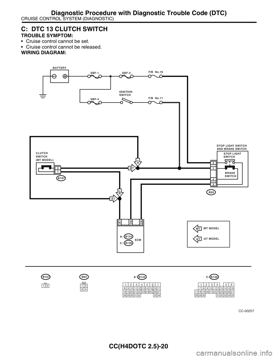
C: DTC 13 CLUTCH SWITCH
TROUBLE SYMPTOM:
Cruise control cannot be set.
Cruise control cannot be released.
WIRING DIAGRAM:
CC-00257
B107B65
12
SBF-1SBF-2F/B No.16
2
1
B65
B1071
3
4
2
C8A1
C9
1234
STOP LIGHT
SWITCH CLUTCH
SWITCH
(MT MODEL)BATTERY
B134
A:
B136
C:ECM
B134
9
30 29 28 323120 19 18 222110 121114
24
34 3327 2617 16123456713
2315
258
B136
9
30 29 28 323120 19 18 22211012
1114
24
34 3327
261612345613
2315
25871735
C: A:
SBF-4F/B No.11
IGNITION
SWITCH
BRAKE
SWITCH STOP LIGHT SWITCH
AND BRAKE SWITCH
AT
:MT MODEL
:AT MODEL
AT
MT
MT
MT
AT
Page 633 of 2870

CC(H4DOTC 2.5)-21
CRUISE CONTROL SYSTEM (DIAGNOSTIC)
Diagnostic Procedure with Diagnostic Trouble Code (DTC)
Step Check Yes No
1 CHECK CLUTCH SWITCH CIRCUIT.
1) Turn the ignition switch to OFF.
2) Disconnect the clutch switch harness con-
nector.
3) Turn the ignition switch to ON.
4) Measure the voltage between harness con-
nector terminal and chassis ground.
Connector & terminal
(B107) No. 2 (+) — Chassis ground (
−):Is the voltage more than 10 V? Go to step 2. Check the fuse
No. 11 (fuse &
relay box).
Check the har-
ness for open or
short between
clutch switch and
fuse & relay box.
2 CHECK CLUTCH SWITCH CIRCUIT.
1) Turn the ignition switch to OFF.
2) Disconnect the ECM harness connector.
3) Measure the resistance between clutch
switch harness connector terminal and ECM
harness connector terminal.
Connector & terminal
(B107) No. 1 — (B134) No. 1:Is the resistance less than 10
Ω? Go to step 3.Repair the har-
ness.
3 CHECK CLUTCH SWITCH.
Remove and check the clutch switch.
cuit is OK.Replace the clutch
switch.
Page 634 of 2870

CC(H4DOTC 2.5)-22
CRUISE CONTROL SYSTEM (DIAGNOSTIC)
Diagnostic Procedure with Diagnostic Trouble Code (DTC)
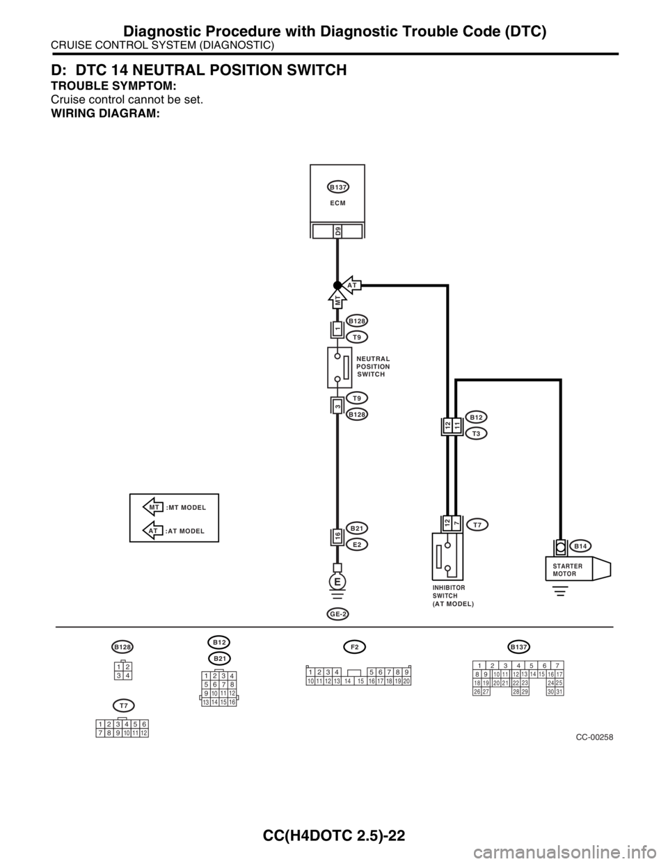
D: DTC 14 NEUTRAL POSITION SWITCH
TROUBLE SYMPTOM:
Cruise control cannot be set.
WIRING DIAGRAM:
CC-00258
B137
D9
B128
T9
T9
B128
1
B21
E216
3
E
B128F2B137
9
30
29 283120 19 18
22
211012
1114
24
27 26
17 16123456713
2315
258 B21123
4
56
78
9
1011 12
1314 15 16
34121234 5678910 11 12 13 14 15 16 17 18 19 20
GE-2
AT
T77 12
B12
T3
AT
:AT MODEL MT
:MT MODEL
1112
B14
MT
123456789101112
T7B12
ECM
NEUTRAL
POSITION
SWITCH
INHIBITOR
SWITCH
(
AT MODEL)STARTER
MOTOR
Page 635 of 2870

CC(H4DOTC 2.5)-23
CRUISE CONTROL SYSTEM (DIAGNOSTIC)
Diagnostic Procedure with Diagnostic Trouble Code (DTC)
Step Check Yes No
1 CHECK TRANSMISSION TYPE.Is the target MT model? Go to step 2.Go to step 5.
2 CHECK NEUTRAL POSITION SWITCH CIR-
CUIT.
1) Turn the ignition switch to OFF.
2) Disconnect the neutral position switch har-
ness connector.
3) Turn the ignition switch to ON.
4) Measure the voltage between harness con-
nector terminal and chassis ground.
Connector & terminal
(B128) No. 1 (+) — Chassis ground (
−): Is the voltage more than 10 V? Go to step 3.Check the harness
for open or short
between neutral
position switch and
ECM.
3 CHECK NEUTRAL POSITION SWITCH CIR-
CUIT.
1) Turn the ignition switch to OFF.
2) Measure the resistance between neutral
position switch harness connector terminal and
chassis ground.
Connector & terminal
(B128) No. 3 — Chassis ground: Is the resistance less than 10
Ω? Go to step 4.Repair the har-
ness.
4 CHECK NEUTRAL POSITION SWITCH.
Remove and check the neutral position switch. Is the neutral position switch
OK? Neutral position
switch circuit is
OK.Replace the neu-
tral position switch.
5 CHECK INHIBITOR SWITCH CIRCUIT.
1) Turn the ignition switch to OFF.
2) Disconnect the inhibitor switch harness
connector.
3) Turn the ignition switch to ON.
4) Measure the voltage between harness con-
nector terminal and chassis ground.
Connector & terminal
(T7) No. 12 (+) — Chassis ground (
−): Is the voltage more than 10 V? Go to step 6.Check the harness
for open or short
between inhibitor
switch and ECM.
6 CHECK INHIBITOR SWITCH CIRCUIT.
1) Turn the ignition switch to OFF.
2) Measure the resistance between inhibitor
switch harness connector terminal and chassis
ground.
Connector & terminal
(T7) No. 7 — Chassis ground: Is the resistance less than 10
Ω? Go to step 7.Repair the har-
ness.
7 CHECK INHIBITOR SWITCH.
Remove and check the inhibitor switch. Is the inhibitor switch OK? Inhibitor switch cir-
cuit is OK.Replace the inhibi-
tor switch.
Page 636 of 2870

CC(H4DOTC 2.5)-24
CRUISE CONTROL SYSTEM (DIAGNOSTIC)
Diagnostic Procedure with Diagnostic Trouble Code (DTC)
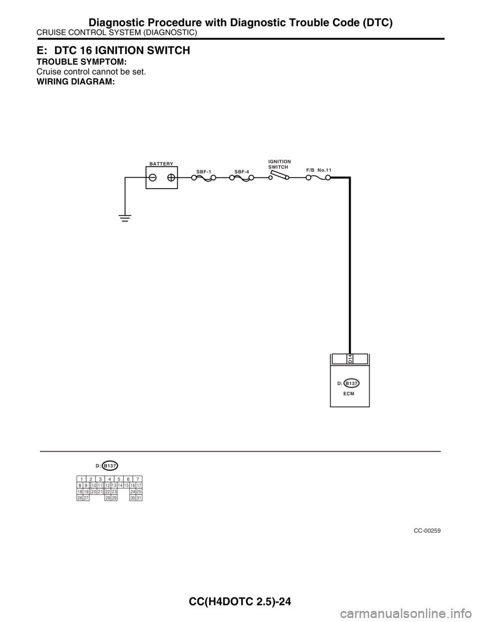
E: DTC 16 IGNITION SWITCH
TROUBLE SYMPTOM:
Cruise control cannot be set.
WIRING DIAGRAM:
CC-00259
B137
ECM
D14
D:
B137
9
30
29 283120 19 18
22
211012
1114
24
27 26
17 16123456713
2315
258D:
SBF-1F/B No.11SBF-4 BATTERYIGNITION
SWITCH
Page 637 of 2870

CC(H4DOTC 2.5)-25
CRUISE CONTROL SYSTEM (DIAGNOSTIC)
Diagnostic Procedure with Diagnostic Trouble Code (DTC)
Step Check Yes No
1 CHECK IGNITION SWITCH CIRCUIT.
1) Turn the ignition switch to OFF.
2) Disconnect the ECM harness connector.
3) Turn the ignition switch to ON.
4) Measure the voltage between harness con-
nector terminal and chassis ground.
Connector & terminal
(B137) No. 14 (+) — Chassis ground (
−): Is the voltage more than 10 V? Check the poor
contact of ECM
connector. Check the fuse
No. 11 (fuse &
relay box).
Check the har-
ness for open or
short between
ignition switch and
ECM.
Page 638 of 2870

CC(H4DOTC 2.5)-26
CRUISE CONTROL SYSTEM (DIAGNOSTIC)
Diagnostic Procedure with Diagnostic Trouble Code (DTC)
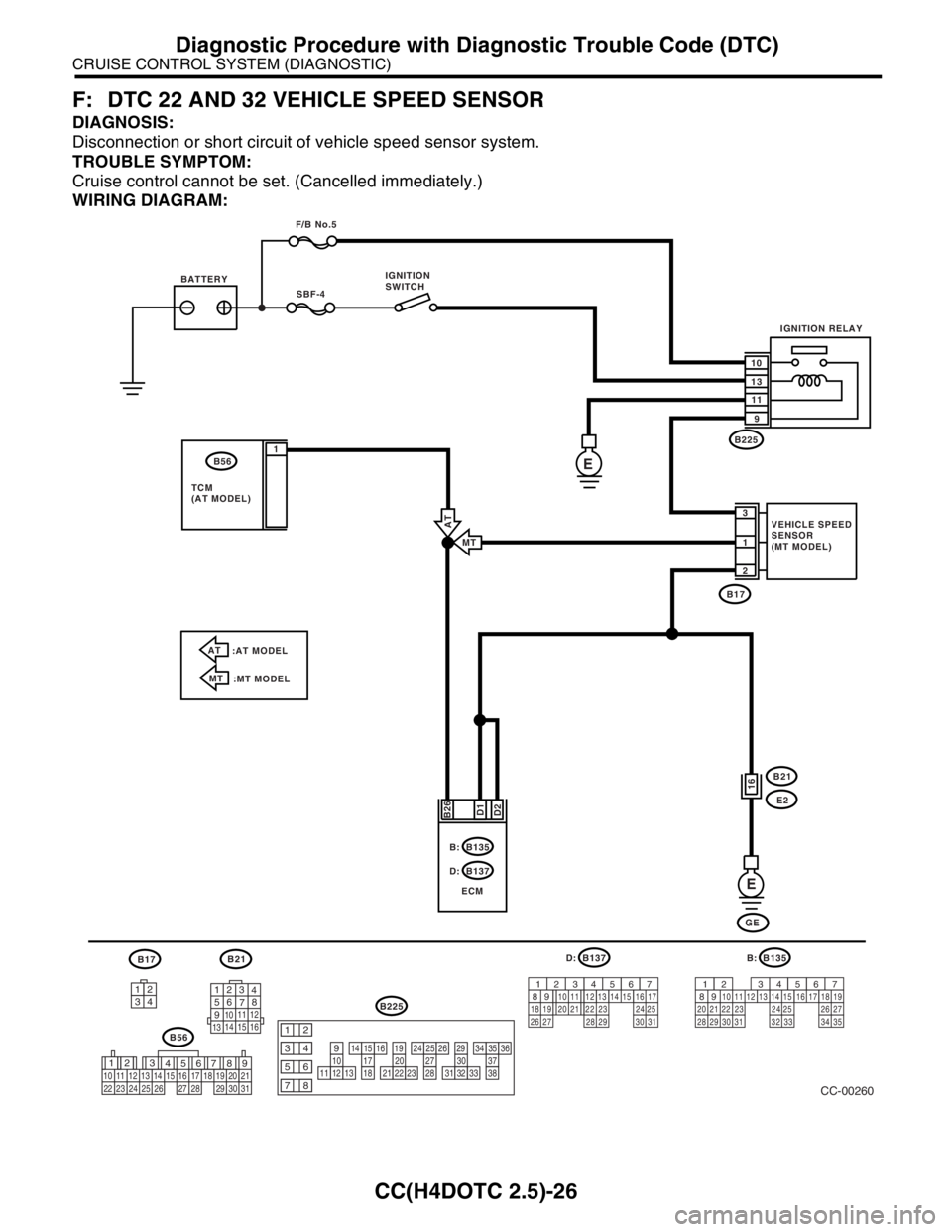
F: DTC 22 AND 32 VEHICLE SPEED SENSOR
DIAGNOSIS:
Disconnection or short circuit of vehicle speed sensor system.
TROUBLE SYMPTOM:
Cruise control cannot be set. (Cancelled immediately.)
WIRING DIAGRAM:
3412
12
789 56 3
410 11 1219 20 21
29 30 31 13
14 151617
27 2818
22 23 24 25 2610111213
1415161718
1920212223
2425262728
2930313233
3435363738
12
934
56
78
B21
123
4
56
78
9
1011 12
1314 15 16
B17B137
9
30
29 283120 19 18
22
211012
1114
24
27 26
17 16123456713
2315
258D:
B56
B225
B135
9
30
29 28312019 18
22 2110
12 1114
2427 2617 16123456713
2315
258B:
32 3334 35
CC-00260
SBF-4
B171
2 3
D2 B26
E
B21
E2
GE B137
ECM D:B135 B: BATTERYIGNITION
SWITCH
VEHICLE SPEED
SENSOR
(MT MODEL) F/B No.5
IGNITION RELAY
10
13
11
9
D1
16
E
B225
B56
TCM
(AT MODEL)1
AT
:AT MODEL
MT
:MT MODELMT
AT
Page 639 of 2870

CC(H4DOTC 2.5)-27
CRUISE CONTROL SYSTEM (DIAGNOSTIC)
Diagnostic Procedure with Diagnostic Trouble Code (DTC)
Step Check Yes No
1 CHECK TRANSMISSION TYPE.Is the target MT model? Go to step 2.Go to step 6.
2 CHECK HARNESS BETWEEN BATTERY
AND VEHICLE SPEED SENSOR.
1) Turn the ignition switch to OFF.
2) Disconnect the harness connector from
vehicle speed sensor.
3) Turn the ignition switch to ON.
4) Measure the voltage between vehicle
speed sensor harness connector terminal and
chassis ground.
Connector & terminal
(B17) No. 3 (+) — Chassis ground (
−):Is the voltage more than 10 V? Go to step 3.Check the harness
for open or short
between fuse and
vehicle speed sen-
sor.
3 CHECK HARNESS BETWEEN ECM AND VE-
HICLE SPEED SENSOR.
1) Turn the ignition switch to OFF.
2) Disconnect the harness connector from
ECM.
3) Measure the resistance between vehicle
speed sensor harness connector terminal and
ECM harness connector terminal.
Connector & terminal
(B17) No. 1 — (B135) No. 26:Is the resistance less than 10
Ω?Go to step 4.Repair the har-
ness.
4 CHECK HARNESS BETWEEN VEHICLE
SPEED SENSOR AND ENGINE GROUND.
1) Turn the ignition switch to OFF.
2) Measure the resistance between vehicle
speed sensor harness connector terminal and
engine ground.
Connector & terminal
(B17) No. 2 — Engine ground:Is the resistance less than 10
Ω?Go to step 5.Repair the har-
ness.
5 CHECK VEHICLE SPEED SENSOR.
1) Connect the harness connector to vehicle
speed sensor.
2) Lift-up the vehicle and support with rigid
racks.
3) Drive the vehicle at speed greater than 20
km/h (12 MPH).
Warning:
Be careful not to be caught up by the run-
ning wheels.
4) Measure the voltage between ECM har-
ness connector terminal and chassis ground.
Connector & terminal
(B135) No. 26 (+) — Chassis ground (
−):Is the voltage 1 V ← → 5 V? Check the poor
contact of ECM
connector.Replace the vehi-
cle speed sensor.
6 CHECK HARNESS BETWEEN ECM AND
TCM.
1) Turn the ignition switch to OFF.
2) Disconnect the harness connector from
ECM and TCM.
3) Measure the resistance between ECM har-
ness connector terminal and TCM harness
connector terminal.
Connector & terminal
(B135) No. 26 — (B56) No. 1:Is the resistance less than 10
Ω?Go to step 7.Repair the har-
ness.
Page 640 of 2870

CC(H4DOTC 2.5)-28
CRUISE CONTROL SYSTEM (DIAGNOSTIC)
Diagnostic Procedure with Diagnostic Trouble Code (DTC)
7 CHECK TCM
1) Connect the harness connector to TCM.
2) Lift-up the vehicle and support with rigid
racks.
3) Drive the vehicle at speed greater than 10
km/h (6 MPH).
Warning:
Be careful not to be caught up by the run-
ning wheels.
4) Measure the voltage between TCM har-
ness connector terminal and chassis ground.
Connector & terminal
(B56) No. 1 (+) — Chassis ground (
−):Is the voltage 1 V ← → 5 V? Check the poor
contact of ECM
harness connec-
tor.Check the poor
contact of TCM
harness connec-
tor. Step Check Yes No