SUBARU FORESTER 2004 Service Repair Manual
Manufacturer: SUBARU, Model Year: 2004, Model line: FORESTER, Model: SUBARU FORESTER 2004Pages: 2870, PDF Size: 38.67 MB
Page 651 of 2870
![SUBARU FORESTER 2004 Service Repair Manual IM-9
IMMOBILIZER (DIAGNOSTIC)
Clear Memory Mode
7. Clear Memory Mode
A: OPERATION
1) On the «Main Menu» display screen, select the
{Each System Check}, and then press the [YES] key.
2) On the «Syst SUBARU FORESTER 2004 Service Repair Manual IM-9
IMMOBILIZER (DIAGNOSTIC)
Clear Memory Mode
7. Clear Memory Mode
A: OPERATION
1) On the «Main Menu» display screen, select the
{Each System Check}, and then press the [YES] key.
2) On the «Syst](/img/17/57426/w960_57426-650.png)
IM-9
IMMOBILIZER (DIAGNOSTIC)
Clear Memory Mode
7. Clear Memory Mode
A: OPERATION
1) On the «Main Menu» display screen, select the
{Each System Check}, and then press the [YES] key.
2) On the «System Selection Menu» display screen,
select the {Engine Control System}, and then press the
[YES] key.
3) Press the [YES] key after displayed information
of engine type.
4) On the «Engine Diagnosis» display screen, se-
lect the {Clear Memory}, and then press the [YES]
key.
5) When the `Done’ is shown on the display screen,
turn the Subaru Select Monitor and ignition switch
to OFF.
NOTE:
After the memory has been cleared, the ISC must be
initialized.To do this, turn the ignition switch to ON po-
sition. Wait 3 seconds before starting the engine.
For detailed operation procedure, refer to the SUB-
ARUSELECT MONITOR OPERATION MANUAL.
Page 652 of 2870

IM-10
IMMOBILIZER (DIAGNOSTIC)
Diagnostics Chart for Immobilizer Warning Light
8. Diagnostics Chart for Immobilizer Warning Light
A: INSPECTION
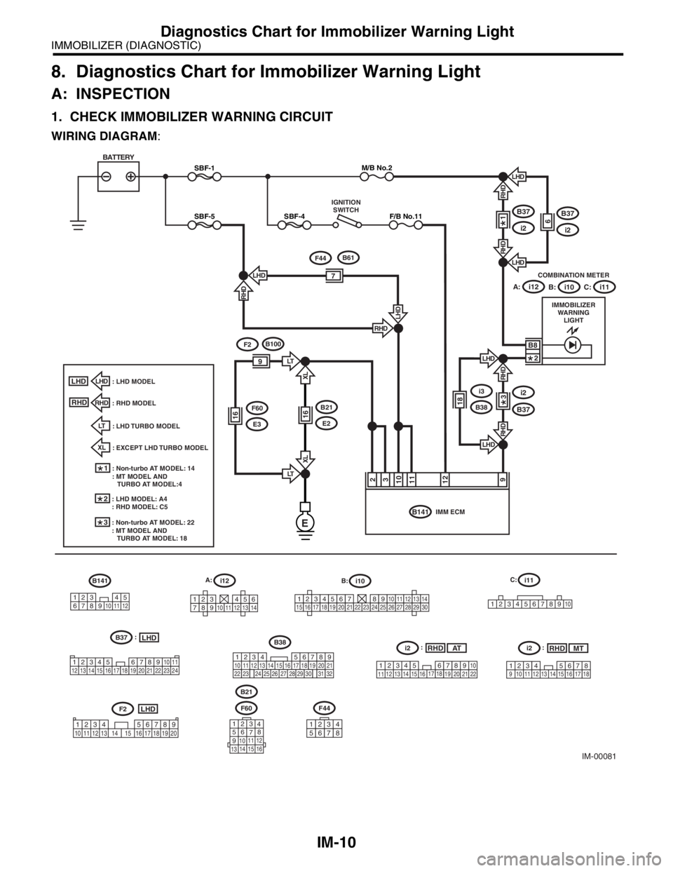
1. CHECK IMMOBILIZER WARNING CIRCUIT
WIRING DIAGRAM:
IM-00081
F60
B21
RHD
SBF-1
SBF-5SBF-4
BATTERY
IMMOBILIZER
WARNING
LIGHT COMBINATION METER
B141IMM ECM
B37
i2
i2
B37
i12
B37
i2
LHD
RHDLHD
6
RHD
M/B No.2
F/B No.11
IGNITION
SWITCH
91211102
B8
3: RHD MODEL
1: Non-turbo AT MODEL: 14
: MT MODEL AND
TURBO AT MODEL:4
i12B141
34 12
89
10 11125
67
219
32
B38
1234 5610 11 12 13 14 15716
23 3019 20
22 26 27 28 29817
24 3118
25
123456789101112131415161718192021222324252627282930
LHDB37
34 12 89
10 11
12 13 14 15 16 17 18 19 20 21 22 23 24567
i10
1
23456789
10
B:
E
A:i10 B:
i11C:
: LHD TURBO MODELLT
: EXCEPT LHD TURBO MODEL
XL
34 12 8910
1112 13 14 15 161718
19 20 21 22567
i2RHD
F2LHD
LHD
LHD
7
F44B61
RHD
RHD
LHD
: LHD MODEL
1
2
i11 C:
LHD
LHD
18
i3
B38
RHD
RHD
3
XL
LT
XL
LT9
1616
F2B100
B21
E2
F60
E3
LHD
RHD
2: LHD MODEL: A4
: RHD MODEL: C5
3: Non-turbo AT MODEL: 22
: MT MODEL AND
TURBO AT MODEL: 18
A:
:
AT:
23 1789 1011121314 15
16 1718456
i2RHDMT:
1234 5678910 11 12 13 14 15 16 17 18 19 20123
4
56
78
9
1011 12
1314 15 16
1234568791011121314
F44
12345678
Page 653 of 2870

IM-11
IMMOBILIZER (DIAGNOSTIC)
Diagnostics Chart for Immobilizer Warning Light
Step Check Yes No
1 CHECK IMMOBILIZER WARNING LIGHT.
1) Turn the ignition switch to OFF.
2) Disconnect the harness connector from
IMM ECM.
3) Connect a resistor (750 Ω) between IMM
ECM harness connector terminal No. 9 and
chassis ground.Does the immobilizer warning
light illuminate?Go to step 2.Go to step 5.
2 CHECK IMM ECM GROUND CIRCUIT.
Measure the resistance between IMM ECM
harness connector terminal and chassis
ground.
Connector & terminal
(B141) No. 2, No. 3 — Chassis ground:Is the resistance less than 10
Ω?Go to step 3.Repair the open
circuit of IMMECM
ground circuit.
3 CHECK IMM ECM IGNITION CIRCUIT.
1) Turn the ignition switch to ON. (engine
OFF.)
2) Measure the voltage between IMM ECM
harness connector terminal and chassis
ground.
Connector & terminal
(B141) No. 12 (+) — Chassis ground(
−):Is the voltage more than 10 V? Go to step 4.Check the harness
for open or short
between IMM
ECM and ignition
switch.
4 CHECK IMM ECM POWER SUPPLY CIR-
CUIT.
1) Turn the ignition switch to OFF.
2) Measure the voltage between IMM ECM
harness connector terminal and chassis
ground.
Connector & terminal
(B141) No. 10, No. 11 (+) — Chassis
ground(
−):Is the voltage more than 10 V? Replace the IMM
ECM
Control Module.>
and then replace
all ignition keys
(including the tran-
sponder). Then
perform teaching
operation. Refer to
teaching opera-
tion manual (Pub.
No. S0820GZ).Check the harness
for open or short
between IMM
ECM and fuse.
5 CHECK COMBINATION METER CIRCUIT.
1) Remove the combination meter.
2) Measure the voltage between combination
meter harness connector terminal and chassis
ground.
Connector & terminal
(i10) No. 8 (+) — Chassis ground (
−):Is the voltage more than 10 V? Go to step 6.Check the harness
for open or short
between combina-
tion meter and
fuse.
6 CHECK COMBINATION METER CIRCUIT.
Measure the resistance between IMM ECM
harness connector terminal and combination
meter harness connector terminal.
Connector & terminal
LHD model
(B141) No. 9 — (i12) No. 4:
RHD model
(B141) No. 9 — (i11) No. 5:Is the resistance less than 10
Ω?Faulty LED.
Replace the com-
bination meter
printed circuit.
Combination
Meter Assembly.>Repair the har-
ness or connector.
Page 654 of 2870

IM-12
IMMOBILIZER (DIAGNOSTIC)
Diagnostics Chart for Immobilizer Warning Light
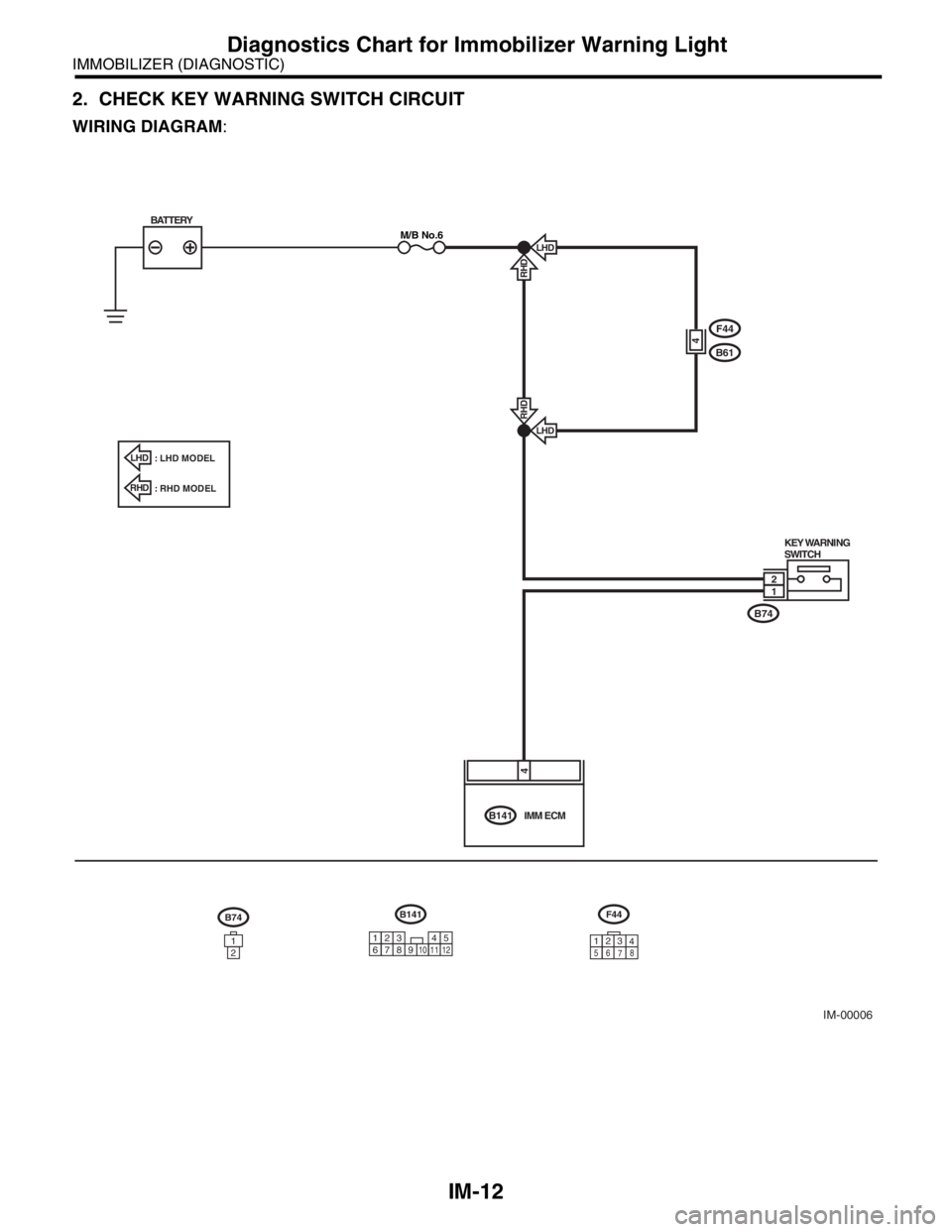
2. CHECK KEY WARNING SWITCH CIRCUIT
WIRING DIAGRAM:
IM-00006
B74
B61
F44
KEY WARNING
SWITCH
B141IMM ECM
LHD
RHDLHD
RHD
BATTERYM/B No.6
4
12
4
B74
1
2
B141
34 12
89
10 11125
67
F44
3
1
56
78
LHD: LHD MODEL
: RHD MODEL
RHD
2
4
Page 655 of 2870

IM-13
IMMOBILIZER (DIAGNOSTIC)
Diagnostics Chart for Immobilizer Warning Light
Step Check Yes No
1 CHECK POWER SUPPLY CIRCUIT.
1) Disconnect the harness connector from key
warning switch.
2) Measure the voltage between key warning
switch harness connector terminal and chassis
ground.
Connector & terminal
(B74) No. 2 (+) — Chassis ground (
−):Is the voltage more than 10 V? Go to step 2.Check the harness
for open or short
between key warn-
ing switch and
fuse.
2 CHECK KEY WARNING SWITCH.
1) Insert the ignition key to the ignition switch.
(OFF or ACC position)
2) Measure the resistance between key warn-
ing switch connector terminals.
Te r m i n a l
No. 1 — No. 2:Is the resistance less than 1
Ω?Go to step 3.Replace the key
warning switch.
3 CHECK KEY WARNING SWITCH.
1) Remove the ignition key from the ignition
switch.
2) Measure the resistance between key warn-
ing switch connector terminals.
Te r m i n a l
No. 1 — No. 2:Is the resistance more than
1 MΩ?Go to step 4.Replace the key
warning switch.
4 CHECK HARNESS BETWEEN KEY WARN-
ING SWITCH AND IMM ECM.
1) Disconnect the harness connector from key
warning switch.
2) Disconnect the harness connector from
IMM ECM.
3) Measure the resistance between key warn-
ing switch harness connector terminal and
IMM ECM harness connector terminal.
Connector & terminal
(B74) No. 1 — (B141) No. 4:Is the resistance less than 10
Ω?Replace the IMM
ECM
Control Module.>
and then replace
all ignition keys
(including the tran-
sponder). Then
perform teaching
operation. Refer to
teaching opera-
tion manual (Pub.
No. S0820GZ).Repair the har-
ness between key
warning switch
and IMM ECM.
Page 656 of 2870

IM-14
IMMOBILIZER (DIAGNOSTIC)
List of Diagnostic Trouble Code (DTC)
9. List of Diagnostic Trouble Code (DTC)
A: LIST
NOTE:
Perform the engine DTC when the DTC except immobilizer DTC is detected.
DTC Item Contents of diagnosis Index No.
P1571Reference Code Incompati-
bilityReference code incompatibility
between IMM ECM and ECM
Diagnostic Trouble Code (DTC).>
P1572EGI — Immobilizer Commu-
nication
(Except Antenna Circuit)Communication failure between
IMM ECM and ECM
Procedure with Diagnostic Trouble Code (DTC).>
P1574Key — Immobilizer Commu-
nicationFailure of IMM ECM to verify key
(transponder) ID code
nostic Trouble Code (DTC).>
P0513 Incorrect Immobilizer Key Incorrect immobilizer key (Use of
unregistered key in IMM ECM)
Trouble Code (DTC).>
P1576EGI Control Module
EEPROMECM malfunctioning
nostic Trouble Code (DTC).>
P1577IMMControl Module
EEPROMIMM ECM malfunctioning
nostic Trouble Code (DTC).>
P1570 ANTENNA Faulty antenna
Page 657 of 2870

IM-15
IMMOBILIZER (DIAGNOSTIC)
Diagnostics Procedure with Diagnostic Trouble Code (DTC)
10.Diagnostics Procedure with Diagnostic Trouble Code (DTC)
A: DTC P1571 REFERENCE CODE INCOMPATIBILITY
DIAGNOSIS:
Reference code incompatibility between IMM ECM and ECM
Step Check Yes No
1 PERFORM TEACHING OPERATION ON IG-
NITION KEY.
Perform teaching operation on all keys of the
vehicle. Refer to the teaching operation man-
ual.Is teaching operation for all
keys completed?END Replace the ECM
Engine Control
Module (ECM).>
Engine Control
Module (ECM).>
41, Engine Con-
trol Module
(ECM).>, IMM
ECM
Control Module.>
and then replace
all ignition keys
(including the tran-
sponder). Then
perform teaching
operation. Refer to
the teaching oper-
ation manual (Pub.
No. S0820GZ).
Page 658 of 2870

IM-16
IMMOBILIZER (DIAGNOSTIC)
Diagnostics Procedure with Diagnostic Trouble Code (DTC)
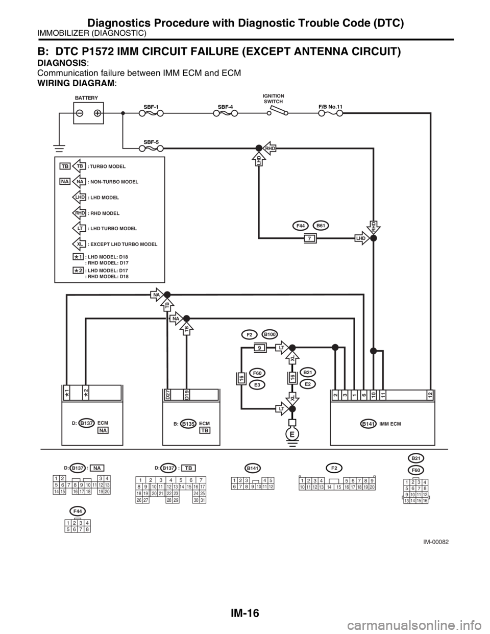
B: DTC P1572 IMM CIRCUIT FAILURE (EXCEPT ANTENNA CIRCUIT)
DIAGNOSIS:
Communication failure between IMM ECM and ECM
WIRING DIAGRAM:
IM-00082
NA
NA
B141IMM ECM ECMB137D:
1261311102
ECMB135B:
TB
TB
: TURBO MODELTB
: NON-TURBO MODEL
NA
D27D19
B137D:B141
34 12
89
10 11125
67
B137D:TBNA
E
RHD
: RHD MODEL
LHD
: LHD MODEL
TB
NA
XL
: EXCEPT LHD TURBO MODEL
LT
: LHD TURBO MODEL
XL
LT
XL
LT9
1616
F2B100
B21
E2
F60
E3
TBNA
:F60
123
4
56
78
9
1011 12
1314 15 16
4
1
53
2618 15 167891011
17 19
20121314
F2
1234 5678910 11 12 13 14 15 16 17 18 19 20
:
B21
1 2
567
82 1
94 310
22 23 11 12 13 14 15
24 25
2616 17
18 19 20 21
27 28 29 30 31
F44
12345678
BATTERYIGNITION
SWITCH
SBF-1
SBF-5
SBF-4F/B No.11
RHD
RHD
7
F44B61
LHD
LHD
1: LHD MODEL: D18
: RHD MODEL: D17
2: LHD MODEL: D17
: RHD MODEL: D18
Page 659 of 2870

IM-17
IMMOBILIZER (DIAGNOSTIC)
Diagnostics Procedure with Diagnostic Trouble Code (DTC)
Step Check Yes No
1 CHECK POWER SUPPLY CIRCUIT OF IMM
ECM.
1) Turn the ignition switch to OFF.
2) Disconnect the harness connector from
IMM ECM.
3) Measure the voltage between IMM ECM
harness connector terminal and chassis
ground.
Connector & terminal
(B141) No. 10, No. 11 (+) — Chassis
ground(
−):Is the voltage more than 10 V? Go to step 2.Check the harness
for open or short
between IMM
ECM and fuse.
2 CHECK IGNITION SWITCH CIRCUIT.
1) Turn the ignition switch to ON. (engine
OFF.)
2) Measure the voltage between IMM ECM
harness connector terminal and chassis
ground.
Connector & terminal
(B141) No. 12 (+) — Chassis ground(
−):Is the voltage more than 10 V? Go to step 3.Check the harness
for open or short
between IMM
ECM and ignition
switch.
3 CHECK GROUND CIRCUIT OF IMM ECM.
1) Turn the ignition switch to OFF.
2) Measure the resistance between IMM ECM
harness connector terminal and chassis
ground.
Connector & terminal
(B141) No. 2, No. 3 — Chassis ground:Is the resistance less than 10
Ω?Go to step 4.Repair the open
circuit of IMMECM
ground circuit.
4 CHECK HARNESS BETWEEN IMM ECM
AND ECM.
1) Disconnect the harness connector from
ECM and IMM ECM.
2) Measure the resistance between IMM ECM
harness connector terminal and ECM harness
connector terminal.
Connector & terminal
Non-turbo LHD model
(B141) No. 1 — (B137) No. 17:
Non-turbo RHD model
(B141) No. 1 — (B137) No. 18:
Turbo model
(B141) No. 1 — (B137) No. 19:Is the resistance less than 10
Ω?Go to step 5.Repair the open
circuit of harness
between IMM
ECM and ECM.
5 CHECK HARNESS BETWEEN IMM ECM
AND ECM.
Measure the resistance between IMM ECM
harness connector terminal and ECM harness
connector terminal.
Connector & terminal
Non-turbo LHD model
(B141) No. 6 — (B137) No. 18:
Non-turbo model
(B141) No. 6 — (B137) No. 17:
Turbo model
(B141) No. 6 — (B137) No. 27:Is the resistance less than 10
Ω?Go to step 6.Repair the open
circuit of harness
between IMM
ECM and ECM.
Page 660 of 2870

IM-18
IMMOBILIZER (DIAGNOSTIC)
Diagnostics Procedure with Diagnostic Trouble Code (DTC)
6 CHECK HARNESS OF COMMUNICATION
LINE.
1) Turn the ignition switch to ON. (engine
OFF.)
2) Measure the voltage between IMM ECM
harness connector terminal and chassis
ground.
Connector & terminal
(B141) No. 1, No. 6 (+) — Chassis ground
(
−):Is the voltage 0 V? Go to step 7.Repair the har-
ness between IMM
ECM and ECM,
because there is
short circuit with
battery voltage line
or ignition switch
“ON” line.
7 CHECK HARNESS OF COMMUNICATION
LINE.
Measure the voltage between ECM harness
connector terminal and engine ground.
Connector & terminal
Non-turbo model
(B137) No. 17, No. 18 (+) — Engine
ground(
−):
Turbo model
(B137) No. 19, No. 27 (+) — Engine
ground(
−):Is the voltage 0 V? Go to step 8.Repair the har-
ness between IMM
ECM and ECM,
because there is
short circuit with
battery voltage line
or ignition switch
“ON” line.
8 CHECK ECM BY COMMUNICATION LINE
CHECK.
1) Connect the harness connector to ECM.
2) Disconnect the harness connector from
IMM ECM.
3) Perform communication line check.
OPERATION, Subaru Select Monitor.>Does “Communication Line not
Shorted” appear on the
screen?Replace the IMM
ECM
Control Module.>
and then replace
all ignition keys
(including the tran-
sponder). Then
perform teaching
operation. Refer to
the teaching oper-
ation manual (Pub.
No. S0820GZ).Replace the ECM.
Engine Control
Module (ECM).>
Engine Control
Module (ECM).>
41, Engine Con-
trol Module
(ECM).> Then per-
form teaching
operation. Refer to
the teaching oper-
ation manual (Pub.
No. S0820GZ). Step Check Yes No