SUBARU FORESTER 2004 Service Repair Manual
Manufacturer: SUBARU, Model Year: 2004, Model line: FORESTER, Model: SUBARU FORESTER 2004Pages: 2870, PDF Size: 38.67 MB
Page 641 of 2870
FUJI HEAVY INDUSTRIES LTD. G8080GE7
2004 FORESTER SERVICE MANUAL QUICK REFERENCE INDEX
BODY SECTION
This service manual has been prepared
to provide SUBARU service personnel
with the necessary information and data
for the correct maintenance and repair
of SUBARU vehicles.
This manual includes the procedures
for maintenance, disassembling, reas-
sembling, inspection and adjustment of
components and diagnostics for guid-
ance of experienced mechanics.
Please peruse and utilize this manual
fully to ensure complete repair work for
satisfying our customers by keeping
their vehicle in optimum condition.
When replacement of parts during
repair work is needed, be sure to use
SUBARU genuine parts.
All information, illustration and specifi-
cations contained in this manual are
based on the latest product information
available at the time of publication
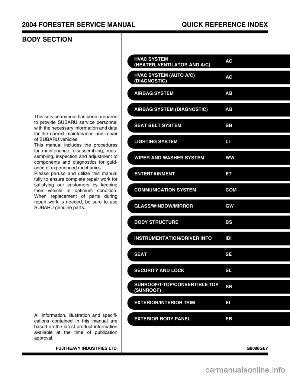
approval.HVAC SYSTEM
(HEATER, VENTILATOR AND A/C)AC
HVAC SYSTEM (AUTO A/C)
(DIAGNOSTIC)AC
AIRBAG SYSTEM AB
AIRBAG SYSTEM (DIAGNOSTIC) AB
SEAT BELT SYSTEM SB
LIGHTING SYSTEM LI
WIPER AND WASHER SYSTEM WW
ENTERTAINMENT ET
COMMUNICATION SYSTEM COM
GLASS/WINDOW/MIRROR GW
BODY STRUCTURE BS
INSTRUMENTATION/DRIVER INFO IDI
SEAT SE
SECURITY AND LOCK SL
SUNROOF/T-TOP/CONVERTIBLE TOP
(SUNROOF)SR
EXTERIOR/INTERIOR TRIM EI
EXTERIOR BODY PANEL EB
Page 642 of 2870
2004 FORESTER SERVICE MANUAL QUICK REFERENCE INDEX
BODY SECTION
G8080GE7
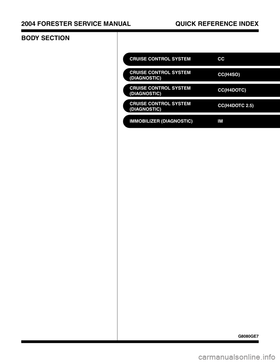
CRUISE CONTROL SYSTEM CC
CRUISE CONTROL SYSTEM
(DIAGNOSTIC)CC(H4SO)
CRUISE CONTROL SYSTEM
(DIAGNOSTIC)CC(H4DOTC)
CRUISE CONTROL SYSTEM
(DIAGNOSTIC)CC(H4DOTC 2.5)
IMMOBILIZER (DIAGNOSTIC) IM
Page 643 of 2870

IMMOBILIZER (DIAGNOSTIC)
IM
Page
1. Basic Diagnostic Procedure ........................................................................2
2. General Description ....................................................................................3
3. Electrical Components Location..................................................................5
4. Immobilizer Control Module I/O Signal........................................................6
5. Subaru Select Monitor.................................................................................7
6. Read Diagnostic Trouble Code (DTC) ........................................................8
7. Clear Memory Mode....................................................................................9
8. Diagnostics Chart for Immobilizer Warning Light ......................................10
9. List of Diagnostic Trouble Code (DTC) .....................................................14
10. Diagnostics Procedure with Diagnostic Trouble Code (DTC) ...................15
Page 644 of 2870

IM-2
IMMOBILIZER (DIAGNOSTIC)
Basic Diagnostic Procedure
1. Basic Diagnostic Procedure
A: PROCEDURE
Step Check Yes No
1 CHECK ILLUMINATION OF IMMOBILIZER
WARNING LIGHT.
1) Turn the ignition switch to OFF or ACC
position.
2) Wait at least 60 seconds.Does the immobilizer warning
light blink?Go to step 2.Check the immobi-
lizer warning light
circuit.
IMMOBILIZER
WARNING CIR-
CUIT, INSPEC-
TION, Diagnostics
Chart for Immobi-
lizer Warning
Light.>
2 CHECK ILLUMINATION OF IMMOBILIZER
WARNING LIGHT.
Remove the key from ignition switch.Does the immobilizer warning
light begin to blink within 1 sec-
ond after the key is removed?Go to step 3.Check the key
switch circuit.
WARNING
SWITCH CIR-
CUIT, INSPEC-
TION, Diagnostics
Chart for Immobi-
lizer Warning
Light.>
3 CHECK ENGINE START.
Turn the ignition switch to START position.Does the engine start? Go to step 4.Go to step 5.
4 CHECK ILLUMINATION OF IMMOBILIZER
WARNING LIGHT.
Turn the ignition switch to ON.Does the immobilizer warning
light illuminate?Check the immobi-
lizer warning light
circuit.
IMMOBILIZER
WARNING CIR-
CUIT, INSPEC-
TION, Diagnostics
Chart for Immobi-
lizer Warning
Light.>Immobilizer sys-
tem is normal.
5 CHECK INDICATION OF DTC ON DISPLAY.
1) Turn the ignition switch to OFF.
2) Connect the Subaru Select Monitor to data
link connector.
3) Turn the ignition switch and Subaru Select
Monitors witch to ON.
4) Read any DTC on the display. Are DTCs indicated on dis-
play?Go to step 6.Repair the related
parts.
6 PERFORM THE DIAGNOSIS.
1) Inspect using “Diagnostics Chart with Trou-
ble Code”.
2) Repair the trouble cause.
3) Perform the clear memory mode.
4) Read any DTC again.Are DTCs indicated on dis-
play?Inspect using
“Diagnostic Proce-
dure with Diagnos-
tic Trouble Code
(DTC)”.
tics Procedure
with Diagnostic
Trouble Code
(DTC).>Finish the diag-
nostics.
Page 645 of 2870
IM-3
IMMOBILIZER (DIAGNOSTIC)
General Description
2. General Description
A: CAUTION
CAUTION:
The airbag system wiring harnesses rout-
ed near the immobilizer control module. All
airbag system wiring harness and connec-
tors are colored yellow. Do not use electrical
test equipment on these circuits.
Be careful not to damage the airbag system
wiring harness when servicing the immobilizer
control module.
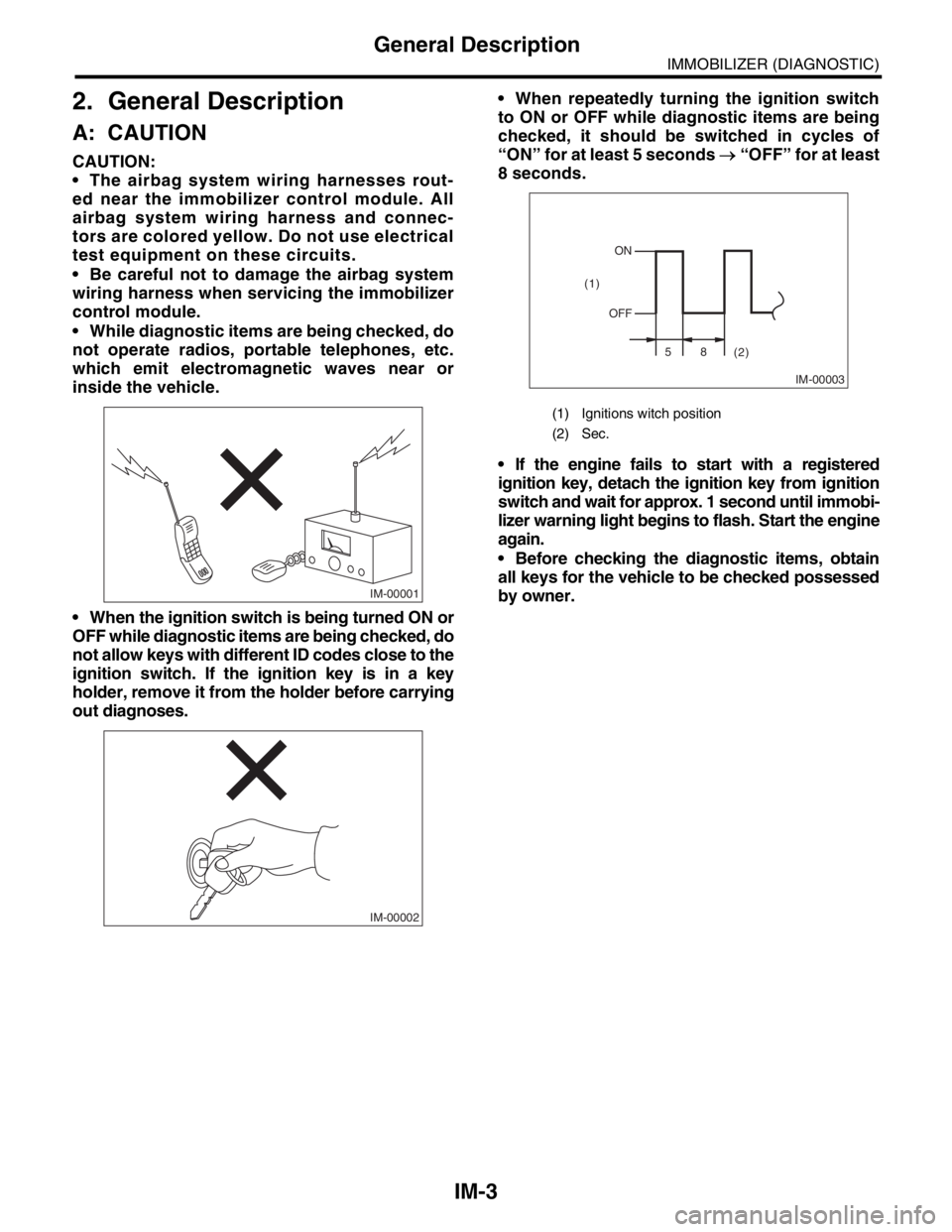
While diagnostic items are being checked, do
not operate radios, portable telephones, etc.
which emit electromagnetic waves near or
inside the vehicle.
When the ignition switch is being turned ON or
OFF while diagnostic items are being checked, do
not allow keys with different ID codes close to the
ignition switch. If the ignition key is in a key
holder, remove it from the holder before carrying
out diagnoses. When repeatedly turning the ignition switch
to ON or OFF while diagnostic items are being
checked, it should be switched in cycles of
“ON” for at least 5 seconds → “OFF” for at least
8 seconds.
If the engine fails to start with a registered
ignition key, detach the ignition key from ignition
switch and wait for approx. 1 second until immobi-
lizer warning light begins to flash. Start the engine
again.
Before checking the diagnostic items, obtain
all keys for the vehicle to be checked possessed
by owner.
IM-00001
IM-00002
(1) Ignitions witch position
(2) Sec.
IM-00003
ON
OFF
58
(2) (1)
Page 646 of 2870
IM-4
IMMOBILIZER (DIAGNOSTIC)
General Description
B: PREPARATION TOOL
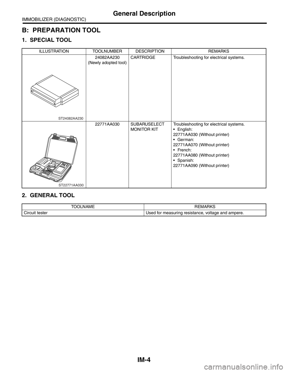
1. SPECIAL TOOL
2. GENERAL TOOL
ILLUSTRATION TOOLNUMBER DESCRIPTION REMARKS
24082AA230
(Newly adopted tool)CARTRIDGE Troubleshooting for electrical systems.
22771AA030 SUBARUSELECT
MONITOR KITTroubleshooting for electrical systems.
English:
22771AA030 (Without printer)
German:
22771AA070 (Without printer)
French:
22771AA080 (Without printer)
Spanish:
22771AA090 (Without printer)
TOOLNAME REMARKS
Circuit tester Used for measuring resistance, voltage and ampere.
ST24082AA230
ST22771AA030
Page 647 of 2870
IM-5
IMMOBILIZER (DIAGNOSTIC)
Electrical Components Location
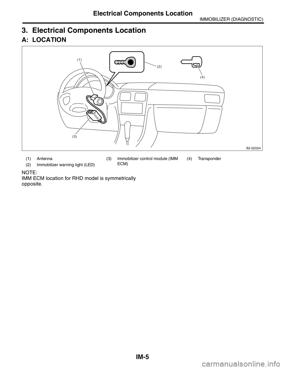
3. Electrical Components Location
A: LOCATION
NOTE:
IMM ECM location for RHD model is symmetrically
opposite.
(1) Antenna (3) Immobilizer control module (IMM
ECM)(4) Transponder
(2) Immobilizer warning light (LED)
IM-00004
(1)
(2)
(3)(4)
Page 648 of 2870

IM-6
IMMOBILIZER (DIAGNOSTIC)
Immobilizer Control Module I/O Signal
4. Immobilizer Control Module I/O
Signal
A: WIRING DIAGRAM
1. IMMOBILIZER
Page 649 of 2870
IM-7
IMMOBILIZER (DIAGNOSTIC)
Subaru Select Monitor
5. Subaru Select Monitor
A: OPERATION
1. HOW TO USE SUBARU SELECT MONI-
TOR
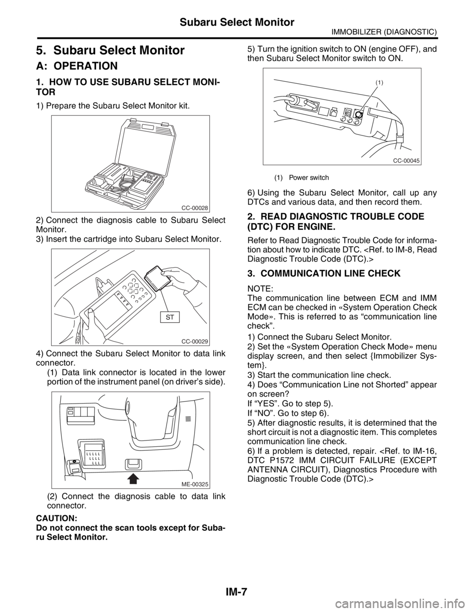
1) Prepare the Subaru Select Monitor kit.
2) Connect the diagnosis cable to Subaru Select
Monitor.
3) Insert the cartridge into Subaru Select Monitor.
4) Connect the Subaru Select Monitor to data link
connector.
(1) Data link connector is located in the lower
portion of the instrument panel (on driver’s side).
(2) Connect the diagnosis cable to data link
connector.
CAUTION:
Do not connect the scan tools except for Suba-
ru Select Monitor.5) Turn the ignition switch to ON (engine OFF), and
then Subaru Select Monitor switch to ON.
6) Using the Subaru Select Monitor, call up any
DTCs and various data, and then record them.
2. READ DIAGNOSTIC TROUBLE CODE
(DTC) FOR ENGINE.
Refer to Read Diagnostic Trouble Code for informa-
tion about how to indicate DTC.
3. COMMUNICATION LINE CHECK
NOTE:
The communication line between ECM and IMM
ECM can be checked in «System Operation Check
Mode». This is referred to as “communication line
check”.
1) Connect the Subaru Select Monitor.
2) Set the «System Operation Check Mode» menu
display screen, and then select {Immobilizer Sys-
tem}.
3) Start the communication line check.
4) Does “Communication Line not Shorted” appear
on screen?
If “YES”. Go to step 5).
If “NO”. Go to step 6).
5) After diagnostic results, it is determined that the
short circuit is not a diagnostic item. This completes
communication line check.
6) If a problem is detected, repair.
ANTENNA CIRCUIT), Diagnostics Procedure with
Diagnostic Trouble Code (DTC).>
CC-00028
CC-00029
ME-00325
(1) Power switch
CC-00045
(1)
Page 650 of 2870

IM-8
IMMOBILIZER (DIAGNOSTIC)
Read Diagnostic Trouble Code (DTC)
6. Read Diagnostic Trouble
Code (DTC)
A: OPERATION
1) On the «Main Menu» display screen, select the
{Each System Check}, and then press the [YES] key.
2) On the «System Selection Menu» display screen,
select the {Engine Control System}, and then press
the [YES] key.
3) Press the [YES] key after displayed information
of engine type.
4) On the «Engine Diagnosis» display screen, se-
lect the {Diagnostic Code(s) Display}, and then
press the [YES] key.
5) On the «Diagnostic Code(s) Display» display
screen, select the {Current Diagnostic Code(s)} or
{History Diagnostic Code(s)}, and then press the
[YES] key.
NOTE:
For detailed operation procedure, refer to the
SUBARU SELECT MONITOR OPERATION MAN-
UAL.
For detailed concerning diagnostic trouble codes,
refer to the List of Diagnostic Trouble Code (DTC).