SUBARU FORESTER 2004 Service Repair Manual
Manufacturer: SUBARU, Model Year: 2004, Model line: FORESTER, Model: SUBARU FORESTER 2004Pages: 2870, PDF Size: 38.67 MB
Page 661 of 2870

IM-19
IMMOBILIZER (DIAGNOSTIC)
Diagnostics Procedure with Diagnostic Trouble Code (DTC)
C: DTC P1574 KEY COMMUNICATION FAILURE
DIAGNOSIS:
Failure of IMM ECM to verify key (transponder) ID code
Step Check Yes No
1 CHECK IMM ECM FUNCTION.
Insert the key to ignition switch (LOCK posi-
tion), measure changes in voltage between
Antenna connector.
Connector & terminal
(B142) No. 1 (+) — No. 2: (
−)Is the voltage −30 to 30 V?
(Approx. 0.1 second after
inserting the key)
Is the voltage 0 V?
(Approx. 1 second after insert-
ing the key)Go to step 2.Replace the IMM
ECM
Control Module.>
and then replace
all ignition keys
(including the tran-
sponder). Then
perform teaching
operation. Refer to
the teaching oper-
ation manual (Pub.
No. S0820GZ).
2 CHECK IGNITION KEY (TRANSPONDER).
1) Remove the key from ignition switch.
2) Start the engine using other keys that have
undergone the teaching operation, furnished
with vehicle.Does the engine start? Replace the igni-
tion key (including
the transponder).
Then perform
teaching opera-
tion. Refer to the
teaching opera-
tion manual (Pub.
No. S0820GZ).Replace the IMM
ECM
Control Module.>
and then replace
all ignition keys
(including the tran-
sponder). Then
perform teaching
operation. Refer to
the teaching oper-
ation manual (Pub.
No. S0820GZ).
Page 662 of 2870

IM-20
IMMOBILIZER (DIAGNOSTIC)
Diagnostics Procedure with Diagnostic Trouble Code (DTC)
D: DTC P0513 INCORRECT IMMOBILIZER KEY
DIAGNOSIS:
Use of unregistered key in IMM ECM
E: DTC P1576 EGI CONTROL MODULE EEPROM
DIAGNOSIS:
ECM malfunctioning
1. REPLACE ECM.
Replace the ECM.
Then perform teaching operation. Refer to the teaching operation manual (Pub. No. S0820GZ).
F: DTC P1577 IMM CONTROL MODULE EEPROM
DIAGNOSIS:
IMM ECM malfunctioning
1. REPLACE IMM ECM.
Replace the IMM ECM
cluding the transponder). Then perform teaching operation. Refer to the teaching operation manual (Pub.
No. S0820GZ).
Step Check Yes No
1 PERFORM TEACHING OPERATION ON IG-
NITION KEY.
Perform teaching operation on all keys of the
vehicle. Refer to the teaching operation man-
ual (Pub. No. S0820GZ).Is teaching operation for all
keys completed?END Replace all ignition
keys (including the
transponder). Go
to step 2.
2 PERFORM TEACHING OPERATION ON IG-
NITION KEY.
Perform teaching operation on all keys with
vehicle. Refer to the teaching operation man-
ual (Pub. No. S0820GZ).Is teaching operation for all
keys completed?END Replace the IMM
ECM
Control Module.>
and then replace
all ignition keys
(including the tran-
sponder). Then
perform teaching
operation. Refer to
the teaching oper-
ation manual (Pub.
No. S0820GZ).
Page 663 of 2870

IM-21
IMMOBILIZER (DIAGNOSTIC)
Diagnostics Procedure with Diagnostic Trouble Code (DTC)
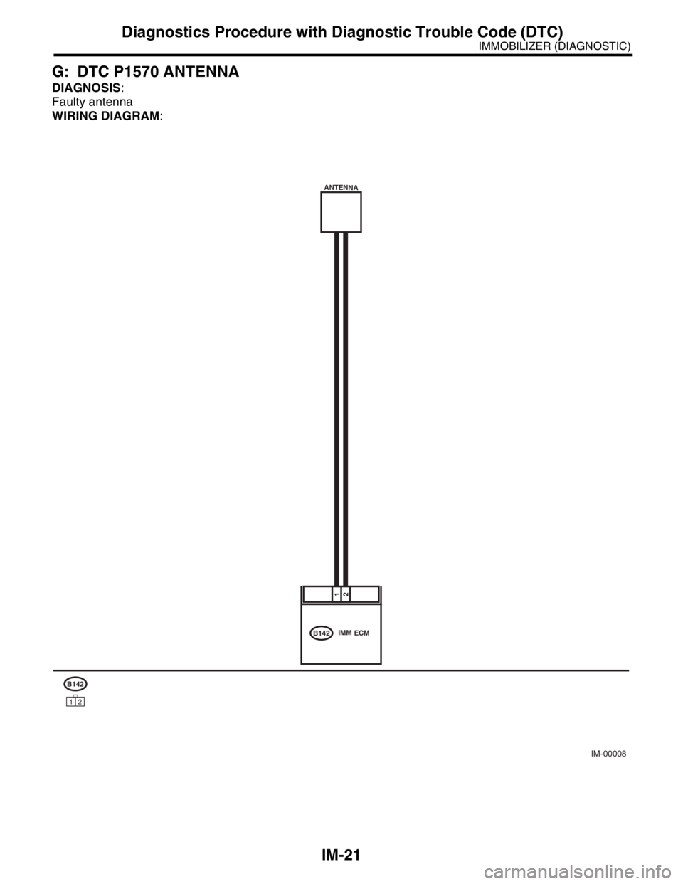
G: DTC P1570 ANTENNA
DIAGNOSIS:
Faulty antenna
WIRING DIAGRAM:
IM-00008
21
B142IMM ECM ANTENNA
B142
12
Page 664 of 2870

IM-22
IMMOBILIZER (DIAGNOSTIC)
Diagnostics Procedure with Diagnostic Trouble Code (DTC)
Step Check Yes No
1 CHECK ANTENNA CIRCUIT.
1) Turn the ignition switch to OFF.
2) Disconnect the harness antenna connector
from IMM ECM.
3) Measure the resistance of antenna circuit.
Connector & terminal
(B142) No. 1 — No. 2:Is the resistance less than 10
Ω?Go to step 2.Replace the
antenna.
lizer Antenna.>
2 CHECK ANTENNA CIRCUIT.
Measure the resistance between antenna har-
ness connector and chassis ground.
Connector & terminal
(B142) No. 1 — Chassis ground:Is the resistance less than 10
Ω?Replace the
antenna.
lizer Antenna.>Go to step 3.
3 CHECK ANTENNA CIRCUIT.
Measure the resistance between antenna har-
ness connector and chassis ground.
Connector & terminal
(B142) No. 2 — Chassis ground:Is the resistance less than 10
Ω?Replace the
antenna.
lizer Antenna.>Go to step 4.
4 CHECK ANTENNA CIRCUIT.
1) Turn the ignition switch to ON. (engine
OFF.)
2) Measure the voltage between antenna har-
ness connector and chassis ground.
Connector & terminal
(B142) No. 1 (+) — Chassis ground(
−):Is the voltage 0 V? Go to step 5.Replace the
antenna.
lizer Antenna.>
5 CHECK ANTENNA CIRCUIT.
Measure the voltage between antenna har-
ness connector and chassis ground.
Connector & terminal
(B142) No. 2 (+) — Chassis ground(
−):Is the voltage 0 V? Go to step 6.Replace the
antenna.
lizer Antenna.>
6 CHECK IMM ECM FUNCTION.
1) Turn the ignition switch to OFF.
2) Connect the antenna harness connector to
IMM ECM.
3) Insert the key to ignition switch, measure
changes in voltage between antenna harness
connector.
Connector & terminal
(B142) No. 1 (+) — No. 2 (
−):Is the voltage −30 to 30 V?
(Approx. 0.1 second after
inserting the key)
Is the voltage 0 V?
(Approx. 1 second after insert-
ing the key)Go to step 7.Replace the IMM
ECM
Control Module.>
and then replace
all ignition keys
(including the tran-
sponder). Then
perform teaching
operation. Refer to
the teaching oper-
ation manual (Pub.
No. S0820GZ).
7 CHECK IGNITION KEY (TRANSPONDER).
1) Remove the key from ignition switch.
2) Start the engine using other keys that have
undergone the teaching operation, furnished
with vehicle.Does the engine start? Replace the igni-
tion key (including
the transponder).
Then perform
teaching opera-
tion. Refer to the
teaching opera-
tion manual (Pub.
No. S0820GZ).Replace the IMM
ECM
Control Module.>
and then replace
all ignition keys
(including the tran-
sponder). Then
perform teaching
operation. Refer to
the teaching oper-
ation manual (Pub.
No. S0820GZ).
Page 665 of 2870

FUJI HEAVY INDUSTRIES LTD. G8080GE6
2004 FORESTER SERVICE MANUAL QUICK REFERENCE INDEX
CHASSIS SECTION
This service manual has been prepared
to provide SUBARU service personnel
with the necessary information and data
for the correct maintenance and repair
of SUBARU vehicles.
This manual includes the procedures
for maintenance, disassembling, reas-
sembling, inspection and adjustment of
components and diagnostics for guid-
ance of experienced mechanics.
Please peruse and utilize this manual
fully to ensure complete repair work for
satisfying our customers by keeping
their vehicle in optimum condition.
When replacement of parts during
repair work is needed, be sure to use
SUBARU genuine parts.
All information, illustration and specifi-
cations contained in this manual are
based on the latest product information
available at the time of publication
approval.FRONT SUSPENSION FS
REAR SUSPENSION RS
WHEEL AND TIRE SYSTEM WT
DIFFERENTIAL DI
TRANSFER CASE TC
DRIVE SHAFT SYSTEM DS
ABS ABS
ABS (DIAGNOSTIC) ABS
BRAKE BR
PARKING BRAKE PB
POWER ASSISTED SYSTEM
(POWER STEERING)PS
Page 666 of 2870

TRANSFER CASE
TC
Page
1. General Description ....................................................................................2
2. Transfer Case and Extension (5MT) ...........................................................3
3. Transfer Clutch and Extension (4AT) ..........................................................4
4. Oil Seal........................................................................................................5
5. Transfer Drive Gear (5MT) ..........................................................................6
6. Transfer Driven Gear (5MT) ........................................................................7
7. Reduction Drive Gear (4AT without VTD) ...................................................8
8. Reduction Driven Gear (4AT without VTD) .................................................9
9. Center Differential .....................................................................................10
10. Transfer Clutch Pressure Test ..................................................................11
11. Transfer Duty Solenoid and Valve Body ...................................................12
Page 667 of 2870

TC-2
TRANSFER CASE
General Description
1. General Description
A: NOTE
For general description, refer to “4AT” or “5MT”
section.
AT model:
MT model:
Page 668 of 2870

TC-3
TRANSFER CASE
Transfer Case and Extension (5MT)
2. Transfer Case and Extension
(5MT)
A: NOTE
For removal, installation and inspection work, refer
to “5MT” section.
Page 669 of 2870

TC-4
TRANSFER CASE
Transfer Clutch and Extension (4AT)
3. Transfer Clutch and Exten-
sion (4AT)
A: NOTE
For removal, installation and inspection work, refer
to “4AT” section.
Page 670 of 2870

TC-5
TRANSFER CASE
Oil Seal
4. Oil Seal
A: NOTE
For removal, installation and inspection work, refer
to “4AT” or “5MT” section.
AT model:
MT model: