wheel SUBARU LEGACY 1999 Service Service Manual
[x] Cancel search | Manufacturer: SUBARU, Model Year: 1999, Model line: LEGACY, Model: SUBARU LEGACY 1999Pages: 1456, PDF Size: 59.93 MB
Page 670 of 1456
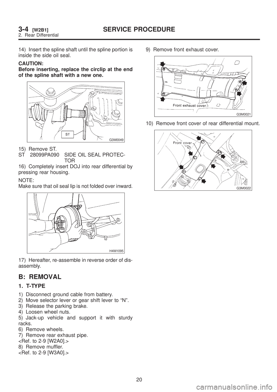
14) Insert the spline shaft until the spline portion is
inside the side oil seal.
CAUTION:
Before inserting, replace the circlip at the end
of the spline shaft with a new one.
G3M0049
15) Remove ST.
ST 28099PA090 SIDE OIL SEAL PROTEC-
TOR
16) Completely insert DOJ into rear differential by
pressing rear housing.
NOTE:
Make sure that oil seal lip is not folded over inward.
H4M1095
17) Hereafter, re-assemble in reverse order of dis-
assembly.
B: REMOVAL
1. T-TYPE
1) Disconnect ground cable from battery.
2) Move selector lever or gear shift lever to ªNº.
3) Release the parking brake.
4) Loosen wheel nuts.
5) Jack-up vehicle and support it with sturdy
racks.
6) Remove wheels.
7) Remove rear exhaust pipe.
8) Remove muffler.
G3M0021
10) Remove front cover of rear differential mount.
G3M0022
20
3-4[W2B1]SERVICE PROCEDURE
2. Rear Differential
Page 672 of 1456
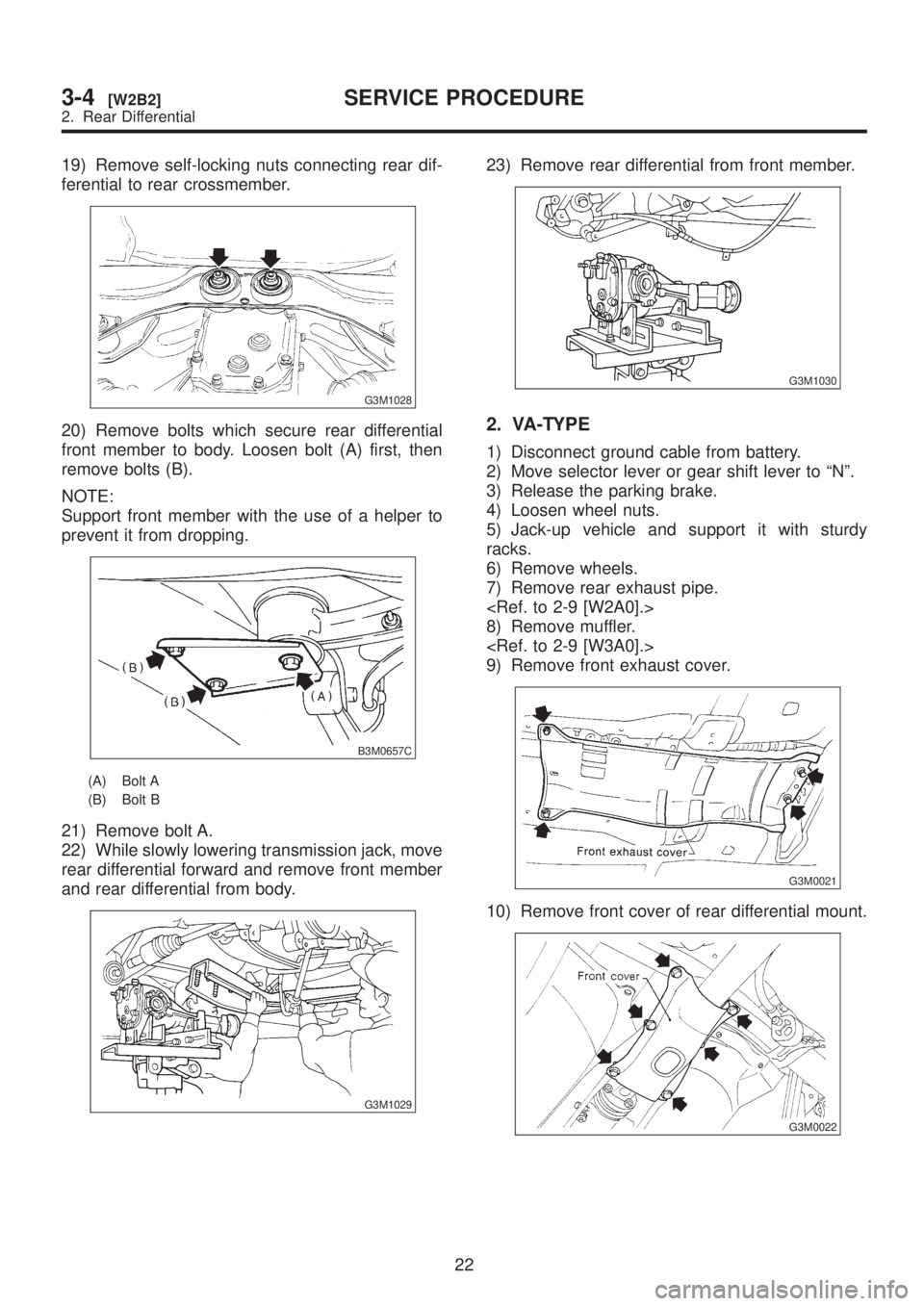
19) Remove self-locking nuts connecting rear dif-
ferential to rear crossmember.
G3M1028
20) Remove bolts which secure rear differential
front member to body. Loosen bolt (A) first, then
remove bolts (B).
NOTE:
Support front member with the use of a helper to
prevent it from dropping.
B3M0657C
(A) Bolt A
(B) Bolt B
21) Remove bolt A.
22) While slowly lowering transmission jack, move
rear differential forward and remove front member
and rear differential from body.
G3M1029
23) Remove rear differential from front member.
G3M1030
2. VA-TYPE
1) Disconnect ground cable from battery.
2) Move selector lever or gear shift lever to ªNº.
3) Release the parking brake.
4) Loosen wheel nuts.
5) Jack-up vehicle and support it with sturdy
racks.
6) Remove wheels.
7) Remove rear exhaust pipe.
8) Remove muffler.
9) Remove front exhaust cover.
G3M0021
10) Remove front cover of rear differential mount.
G3M0022
22
3-4[W2B2]SERVICE PROCEDURE
2. Rear Differential
Page 698 of 1456
NOTE:
When installing rear differential front member, do
not confuse the installation sequence of the upper
and lower stoppers.
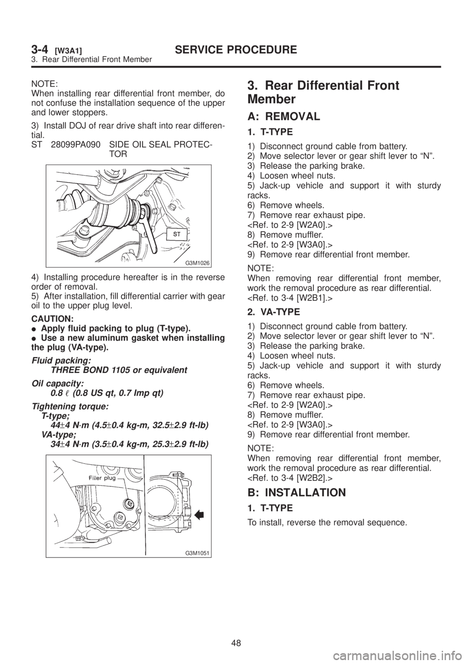
3) Install DOJ of rear drive shaft into rear differen-
tial.
ST 28099PA090 SIDE OIL SEAL PROTEC-
TOR
G3M1026
4) Installing procedure hereafter is in the reverse
order of removal.
5) After installation, fill differential carrier with gear
oil to the upper plug level.
CAUTION:
IApply fluid packing to plug (T-type).
IUse a new aluminum gasket when installing
the plug (VA-type).
Fluid packing:
THREE BOND 1105 or equivalent
Oil capacity:
0.8
(0.8 US qt, 0.7 Imp qt)
Tightening torque:
T-type;
44
±4 N´m (4.5±0.4 kg-m, 32.5±2.9 ft-lb)
VA-type;
34
±4 N´m (3.5±0.4 kg-m, 25.3±2.9 ft-lb)
G3M1051
3. Rear Differential Front
Member
A: REMOVAL
1. T-TYPE
1) Disconnect ground cable from battery.
2) Move selector lever or gear shift lever to ªNº.
3) Release the parking brake.
4) Loosen wheel nuts.
5) Jack-up vehicle and support it with sturdy
racks.
6) Remove wheels.
7) Remove rear exhaust pipe.
8) Remove muffler.
9) Remove rear differential front member.
NOTE:
When removing rear differential front member,
work the removal procedure as rear differential.
2. VA-TYPE
1) Disconnect ground cable from battery.
2) Move selector lever or gear shift lever to ªNº.
3) Release the parking brake.
4) Loosen wheel nuts.
5) Jack-up vehicle and support it with sturdy
racks.
6) Remove wheels.
7) Remove rear exhaust pipe.
8) Remove muffler.
9) Remove rear differential front member.
NOTE:
When removing rear differential front member,
work the removal procedure as rear differential.
B: INSTALLATION
1. T-TYPE
To install, reverse the removal sequence.
48
3-4[W3A1]SERVICE PROCEDURE
3. Rear Differential Front Member
Page 699 of 1456
NOTE:
When installing rear differential front member, do
not confuse the installation sequence of the upper
and lower stoppers.
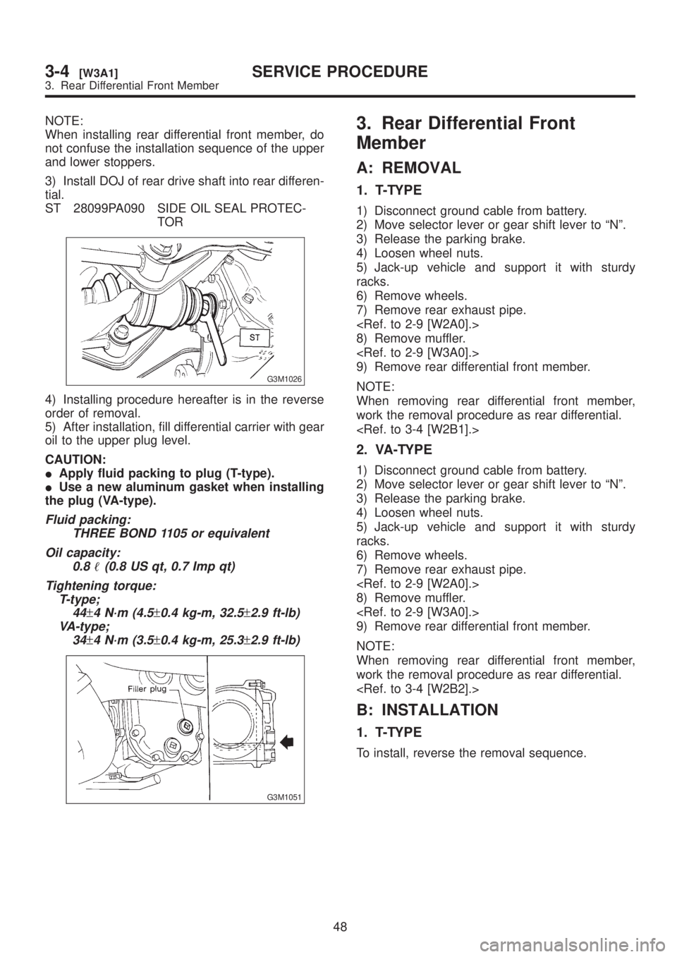
3) Install DOJ of rear drive shaft into rear differen-
tial.
ST 28099PA090 SIDE OIL SEAL PROTEC-
TOR
G3M1026
4) Installing procedure hereafter is in the reverse
order of removal.
5) After installation, fill differential carrier with gear
oil to the upper plug level.
CAUTION:
IApply fluid packing to plug (T-type).
IUse a new aluminum gasket when installing
the plug (VA-type).
Fluid packing:
THREE BOND 1105 or equivalent
Oil capacity:
0.8
(0.8 US qt, 0.7 Imp qt)
Tightening torque:
T-type;
44
±4 N´m (4.5±0.4 kg-m, 32.5±2.9 ft-lb)
VA-type;
34
±4 N´m (3.5±0.4 kg-m, 25.3±2.9 ft-lb)
G3M1051
3. Rear Differential Front
Member
A: REMOVAL
1. T-TYPE
1) Disconnect ground cable from battery.
2) Move selector lever or gear shift lever to ªNº.
3) Release the parking brake.
4) Loosen wheel nuts.
5) Jack-up vehicle and support it with sturdy
racks.
6) Remove wheels.
7) Remove rear exhaust pipe.
8) Remove muffler.
9) Remove rear differential front member.
NOTE:
When removing rear differential front member,
work the removal procedure as rear differential.
2. VA-TYPE
1) Disconnect ground cable from battery.
2) Move selector lever or gear shift lever to ªNº.
3) Release the parking brake.
4) Loosen wheel nuts.
5) Jack-up vehicle and support it with sturdy
racks.
6) Remove wheels.
7) Remove rear exhaust pipe.
8) Remove muffler.
9) Remove rear differential front member.
NOTE:
When removing rear differential front member,
work the removal procedure as rear differential.
B: INSTALLATION
1. T-TYPE
To install, reverse the removal sequence.
48
3-4[W3A1]SERVICE PROCEDURE
3. Rear Differential Front Member
Page 702 of 1456
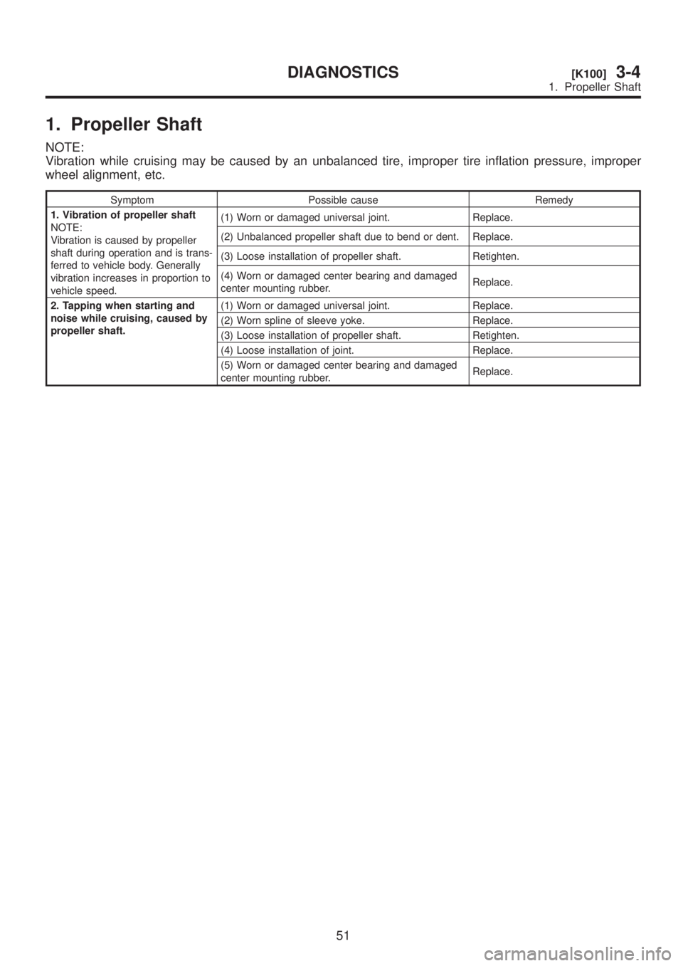
1. Propeller Shaft
NOTE:
Vibration while cruising may be caused by an unbalanced tire, improper tire inflation pressure, improper
wheel alignment, etc.
Symptom Possible cause Remedy
1. Vibration of propeller shaft
NOTE:
Vibration is caused by propeller
shaft during operation and is trans-
ferred to vehicle body. Generally
vibration increases in proportion to
vehicle speed.(1) Worn or damaged universal joint. Replace.
(2) Unbalanced propeller shaft due to bend or dent. Replace.
(3) Loose installation of propeller shaft. Retighten.
(4) Worn or damaged center bearing and damaged
center mounting rubber.Replace.
2. Tapping when starting and
noise while cruising, caused by
propeller shaft.(1) Worn or damaged universal joint. Replace.
(2) Worn spline of sleeve yoke. Replace.
(3) Loose installation of propeller shaft. Retighten.
(4) Loose installation of joint. Replace.
(5) Worn or damaged center bearing and damaged
center mounting rubber.Replace.
51
[K100]3-4DIAGNOSTICS
1. Propeller Shaft
Page 703 of 1456
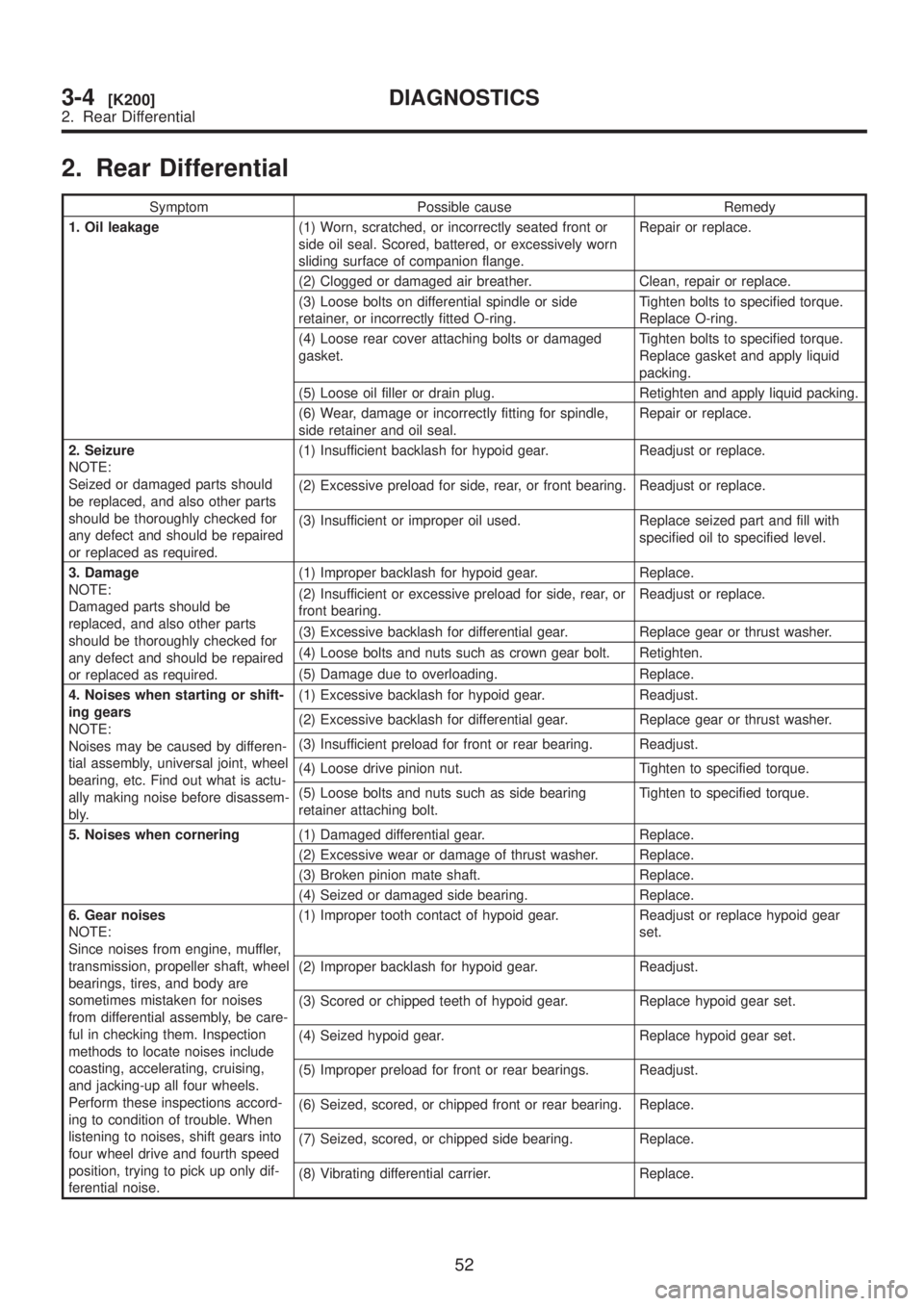
2. Rear Differential
Symptom Possible cause Remedy
1. Oil leakage(1) Worn, scratched, or incorrectly seated front or
side oil seal. Scored, battered, or excessively worn
sliding surface of companion flange.Repair or replace.
(2) Clogged or damaged air breather. Clean, repair or replace.
(3) Loose bolts on differential spindle or side
retainer, or incorrectly fitted O-ring.Tighten bolts to specified torque.
Replace O-ring.
(4) Loose rear cover attaching bolts or damaged
gasket.Tighten bolts to specified torque.
Replace gasket and apply liquid
packing.
(5) Loose oil filler or drain plug. Retighten and apply liquid packing.
(6) Wear, damage or incorrectly fitting for spindle,
side retainer and oil seal.Repair or replace.
2. Seizure
NOTE:
Seized or damaged parts should
be replaced, and also other parts
should be thoroughly checked for
any defect and should be repaired
or replaced as required.(1) Insufficient backlash for hypoid gear. Readjust or replace.
(2) Excessive preload for side, rear, or front bearing. Readjust or replace.
(3) Insufficient or improper oil used. Replace seized part and fill with
specified oil to specified level.
3. Damage
NOTE:
Damaged parts should be
replaced, and also other parts
should be thoroughly checked for
any defect and should be repaired
or replaced as required.(1) Improper backlash for hypoid gear. Replace.
(2) Insufficient or excessive preload for side, rear, or
front bearing.Readjust or replace.
(3) Excessive backlash for differential gear. Replace gear or thrust washer.
(4) Loose bolts and nuts such as crown gear bolt. Retighten.
(5) Damage due to overloading. Replace.
4. Noises when starting or shift-
ing gears
NOTE:
Noises may be caused by differen-
tial assembly, universal joint, wheel
bearing, etc. Find out what is actu-
ally making noise before disassem-
bly.(1) Excessive backlash for hypoid gear. Readjust.
(2) Excessive backlash for differential gear. Replace gear or thrust washer.
(3) Insufficient preload for front or rear bearing. Readjust.
(4) Loose drive pinion nut. Tighten to specified torque.
(5) Loose bolts and nuts such as side bearing
retainer attaching bolt.Tighten to specified torque.
5. Noises when cornering(1) Damaged differential gear. Replace.
(2) Excessive wear or damage of thrust washer. Replace.
(3) Broken pinion mate shaft. Replace.
(4) Seized or damaged side bearing. Replace.
6. Gear noises
NOTE:
Since noises from engine, muffler,
transmission, propeller shaft, wheel
bearings, tires, and body are
sometimes mistaken for noises
from differential assembly, be care-
ful in checking them. Inspection
methods to locate noises include
coasting, accelerating, cruising,
and jacking-up all four wheels.
Perform these inspections accord-
ing to condition of trouble. When
listening to noises, shift gears into
four wheel drive and fourth speed
position, trying to pick up only dif-
ferential noise.(1) Improper tooth contact of hypoid gear. Readjust or replace hypoid gear
set.
(2) Improper backlash for hypoid gear. Readjust.
(3) Scored or chipped teeth of hypoid gear. Replace hypoid gear set.
(4) Seized hypoid gear. Replace hypoid gear set.
(5) Improper preload for front or rear bearings. Readjust.
(6) Seized, scored, or chipped front or rear bearing. Replace.
(7) Seized, scored, or chipped side bearing. Replace.
(8) Vibrating differential carrier. Replace.
52
3-4[K200]DIAGNOSTICS
2. Rear Differential
Page 705 of 1456
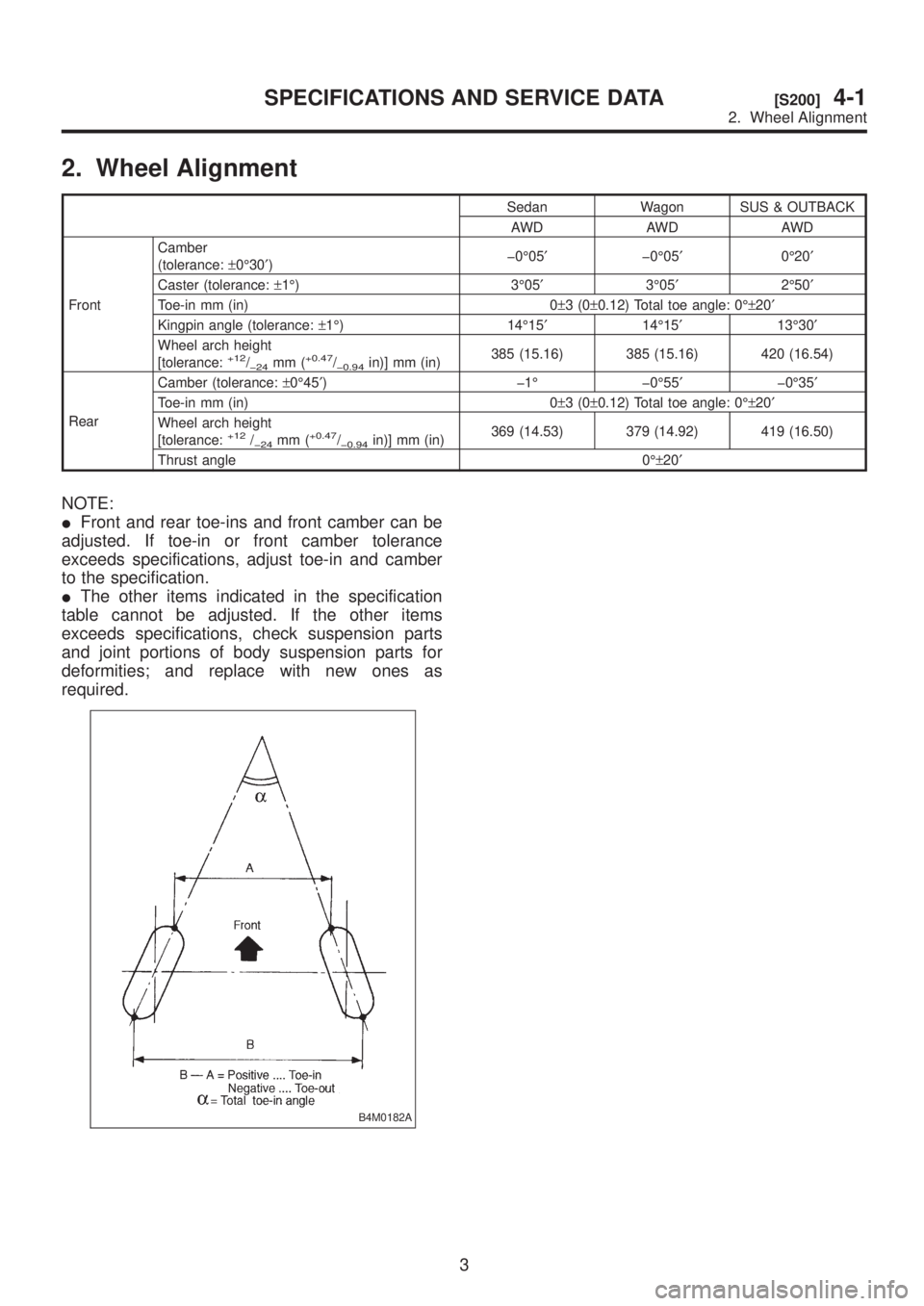
2. Wheel Alignment
Sedan Wagon SUS & OUTBACK
AWD AWD AWD
FrontCamber
(tolerance:±0É30¢)þ0É05¢þ0É05¢0É20¢
Caster (tolerance:±1É) 3É05¢3É05¢2É50¢
Toe-in mm (in) 0±3(0±0.12) Total toe angle: 0ɱ20¢
Kingpin angle (tolerance:±1É) 14É15¢14É15¢13É30¢
Wheel arch height
[tolerance:
+12/þ24mm (+0.47/þ0.94in)] mm (in)385 (15.16) 385 (15.16) 420 (16.54)
RearCamber (tolerance:±0É45¢) þ1É þ0É55¢þ0É35¢
Toe-in mm (in) 0±3(0±0.12) Total toe angle: 0ɱ20¢
Wheel arch height
[tolerance:
+12/þ24mm (+0.47/þ0.94in)] mm (in)369 (14.53) 379 (14.92) 419 (16.50)
Thrust angle 0ɱ20¢
NOTE:
IFront and rear toe-ins and front camber can be
adjusted. If toe-in or front camber tolerance
exceeds specifications, adjust toe-in and camber
to the specification.
IThe other items indicated in the specification
table cannot be adjusted. If the other items
exceeds specifications, check suspension parts
and joint portions of body suspension parts for
deformities; and replace with new ones as
required.
B4M0182A
3
[S200]4-1SPECIFICATIONS AND SERVICE DATA
2. Wheel Alignment
Page 709 of 1456
![SUBARU LEGACY 1999 Service Service Manual 1. On-car Services
A: WHEEL ALIGNMENT
PROCEDURES
Check, adjust and/or measure wheel alignment in
accordance with procedures indicated in figure:
B4M1088A
7
[W1A0]4-1SERVICE PROCEDURE
1. On-car Service](/img/17/57435/w960_57435-708.png "SUBARU LEGACY 1999 Service Service Manual 1. On-car Services
A: WHEEL ALIGNMENT
PROCEDURES
Check, adjust and/or measure wheel alignment in
accordance with procedures indicated in figure:
B4M1088A
7
[W1A0]4-1SERVICE PROCEDURE
1. On-car Service")
1. On-car Services
A: WHEEL ALIGNMENT
PROCEDURES
Check, adjust and/or measure wheel alignment in
accordance with procedures indicated in figure:
B4M1088A
7
[W1A0]4-1SERVICE PROCEDURE
1. On-car Services
Page 710 of 1456
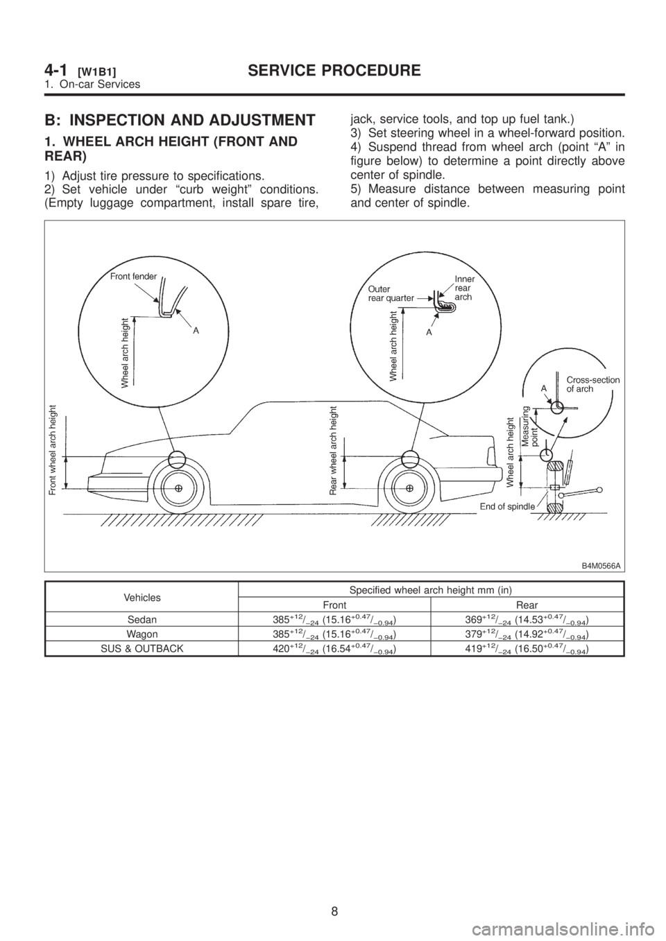
B: INSPECTION AND ADJUSTMENT
1. WHEEL ARCH HEIGHT (FRONT AND
REAR)
1) Adjust tire pressure to specifications.
2) Set vehicle under ªcurb weightº conditions.
(Empty luggage compartment, install spare tire,jack, service tools, and top up fuel tank.)
3) Set steering wheel in a wheel-forward position.
4) Suspend thread from wheel arch (point ªAº in
figure below) to determine a point directly above
center of spindle.
5) Measure distance between measuring point
and center of spindle.
B4M0566A
VehiclesSpecified wheel arch height mm (in)
Front Rear
Sedan 385
+12/þ24(15.16+0.47/þ0.94) 369+12/þ24(14.53+0.47/þ0.94)
Wagon 385+12/þ24(15.16+0.47/þ0.94) 379+12/þ24(14.92+0.47/þ0.94)
SUS & OUTBACK 420+12/þ24(16.54+0.47/þ0.94) 419+12/þ24(16.50+0.47/þ0.94)
8
4-1[W1B1]SERVICE PROCEDURE
1. On-car Services
Page 711 of 1456
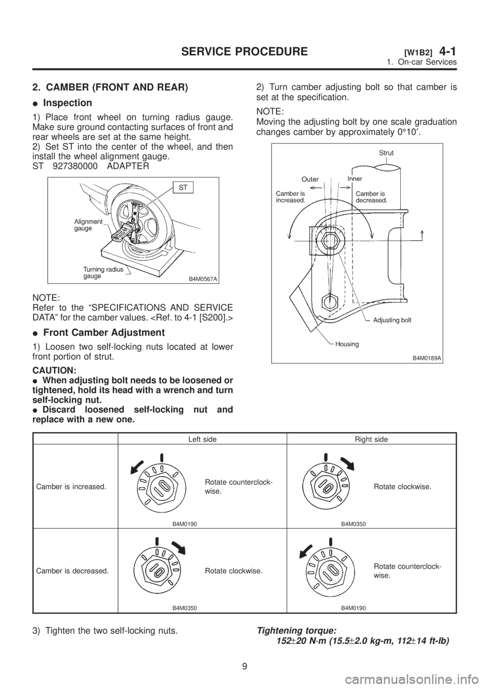
2. CAMBER (FRONT AND REAR)
IInspection
1) Place front wheel on turning radius gauge.
Make sure ground contacting surfaces of front and
rear wheels are set at the same height.
2) Set ST into the center of the wheel, and then
install the wheel alignment gauge.
ST 927380000 ADAPTER
B4M0567A
NOTE:
Refer to the ªSPECIFICATIONS AND SERVICE
DATAº for the camber values.
IFront Camber Adjustment
1) Loosen two self-locking nuts located at lower
front portion of strut.
CAUTION:
IWhen adjusting bolt needs to be loosened or
tightened, hold its head with a wrench and turn
self-locking nut.
IDiscard loosened self-locking nut and
replace with a new one.2) Turn camber adjusting bolt so that camber is
set at the specification.
NOTE:
Moving the adjusting bolt by one scale graduation
changes camber by approximately 0É10¢.
B4M0189A
Left side Right side
Camber is increased.
B4M0190
Rotate counterclock-
wise.
B4M0350
Rotate clockwise.
Camber is decreased.
B4M0350
Rotate clockwise.
B4M0190
Rotate counterclock-
wise.
3) Tighten the two self-locking nuts.Tightening torque:
152
±20 N´m (15.5±2.0 kg-m, 112±14 ft-lb)
9
[W1B2]4-1SERVICE PROCEDURE
1. On-car Services