wheel SUBARU LEGACY 1999 Service Workshop Manual
[x] Cancel search | Manufacturer: SUBARU, Model Year: 1999, Model line: LEGACY, Model: SUBARU LEGACY 1999Pages: 1456, PDF Size: 59.93 MB
Page 712 of 1456
3. CASTER (FRONT)
IInspection
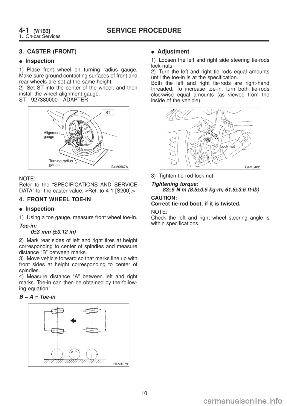
1) Place front wheel on turning radius gauge.
Make sure ground contacting surfaces of front and
rear wheels are set at the same height.
2) Set ST into the center of the wheel, and then
install the wheel alignment gauge.
ST 927380000 ADAPTER
B4M0567A
NOTE:
Refer to the ªSPECIFICATIONS AND SERVICE
DATAº for the caster value.
4. FRONT WHEEL TOE-IN
IInspection
1) Using a toe gauge, measure front wheel toe-in.
Toe-in:
0
±3mm(±0.12 in)
2) Mark rear sides of left and right tires at height
corresponding to center of spindles and measure
distance ªBº between marks.
3) Move vehicle forward so that marks line up with
front sides at height corresponding to center of
spindles.
4) Measure distance ªAº between left and right
marks. Toe-in can then be obtained by the follow-
ing equation:
B þ A = Toe-in
H4M1279
IAdjustment
1) Loosen the left and right side steering tie-rods
lock nuts.
2) Turn the left and right tie rods equal amounts
until the toe-in is at the specification.
Both the left and right tie-rods are right-hand
threaded. To increase toe-in, turn both tie-rods
clockwise equal amounts (as viewed from the
inside of the vehicle).
G4M0482
3) Tighten tie-rod lock nut.
Tightening torque:
83
±5 N´m (8.5±0.5 kg-m, 61.5±3.6 ft-lb)
CAUTION:
Correct tie-rod boot, if it is twisted.
NOTE:
Check the left and right wheel steering angle is
within specifications.
10
4-1[W1B3]SERVICE PROCEDURE
1. On-car Services
Page 713 of 1456
5. REAR WHEEL TOE-IN
IInspection
1) Using a toe-in gauge, measure rear wheel toe-
in.
Toe-in:
0
±3mm(±0.12 in)
2) Mark rear sides of left and right tires at height
corresponding to center of spindles and measure
distance ªBº between marks.
3) Move vehicle forward so that marks line up with
front sides at height corresponding to center of
spindles.
4) Measure distance ªAº between left and right
marks. Toe-in can then be obtained by the follow-
ing equation:
B þ A = Toe-in
H4M1279
IAdjustment
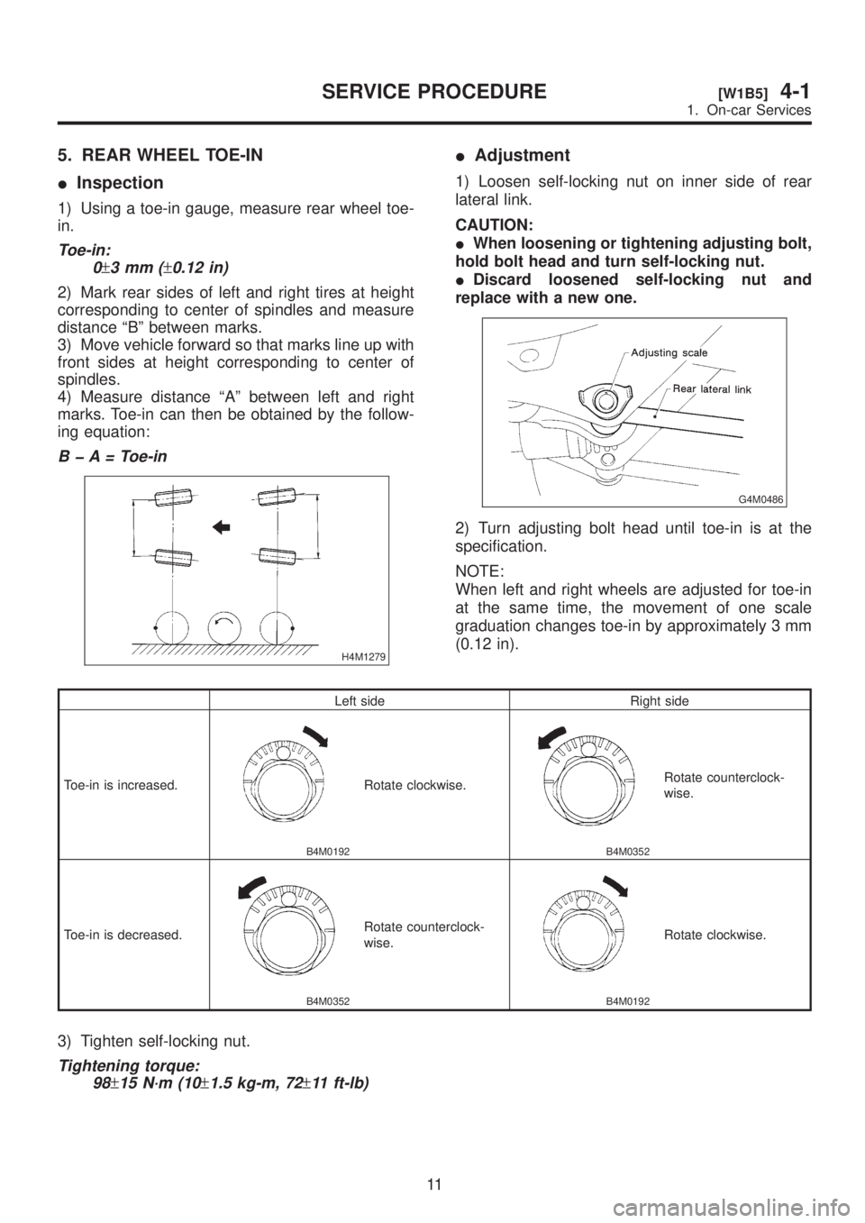
1) Loosen self-locking nut on inner side of rear
lateral link.
CAUTION:
IWhen loosening or tightening adjusting bolt,
hold bolt head and turn self-locking nut.
IDiscard loosened self-locking nut and
replace with a new one.
G4M0486
2) Turn adjusting bolt head until toe-in is at the
specification.
NOTE:
When left and right wheels are adjusted for toe-in
at the same time, the movement of one scale
graduation changes toe-in by approximately 3 mm
(0.12 in).
Left side Right side
Toe-in is increased.
B4M0192
Rotate clockwise.
B4M0352
Rotate counterclock-
wise.
Toe-in is decreased.
B4M0352
Rotate counterclock-
wise.
B4M0192
Rotate clockwise.
3) Tighten self-locking nut.
Tightening torque:
98
±15 N´m (10±1.5 kg-m, 72±11 ft-lb)
11
[W1B5]4-1SERVICE PROCEDURE
1. On-car Services
Page 714 of 1456
6. THRUST ANGLE
IInspection
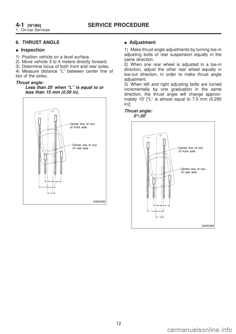
1) Position vehicle on a level surface.
2) Move vehicle 3 to 4 meters directly forward.
3) Determine locus of both front and rear axles.
4) Measure distance ªLº between center line of
loci of the axles.
Thrust angle:
Less than 20
¢when ªLº is equal to or
less than 15 mm (0.59 in).
G4M0488
IAdjustment
1) Make thrust angle adjustments by turning toe-in
adjusting bolts of rear suspension equally in the
same direction.
2) When one rear wheel is adjusted in a toe-in
direction, adjust the other rear wheel equally in
toe-out direction, in order to make thrust angle
adjustment.
3) When left and right adjusting bolts are turned
incrementally by one graduation in the same
direction, the thrust angle will change approxi-
mately 10' [ªLº is almost equal to 7.5 mm (0.295
in)].
Thrust angle:
0É
±20¢
G4M0488
12
4-1[W1B6]SERVICE PROCEDURE
1. On-car Services
Page 715 of 1456
NOTE:
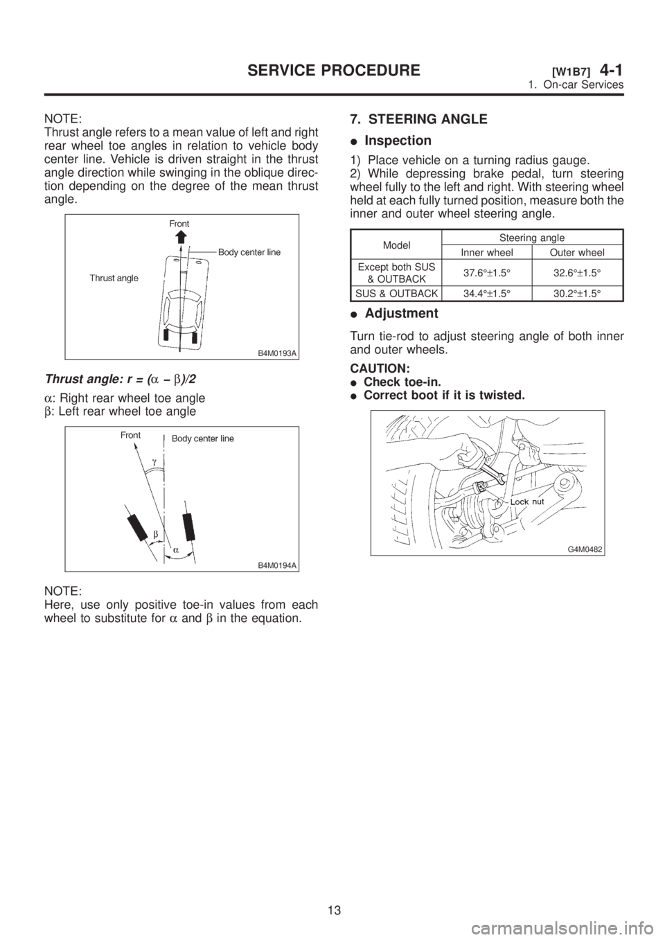
Thrust angle refers to a mean value of left and right
rear wheel toe angles in relation to vehicle body
center line. Vehicle is driven straight in the thrust
angle direction while swinging in the oblique direc-
tion depending on the degree of the mean thrust
angle.
B4M0193A
Thrust angle:r=(aþb)/2
a: Right rear wheel toe angle
b: Left rear wheel toe angle
B4M0194A
NOTE:
Here, use only positive toe-in values from each
wheel to substitute foraandbin the equation.
7. STEERING ANGLE
IInspection
1) Place vehicle on a turning radius gauge.
2) While depressing brake pedal, turn steering
wheel fully to the left and right. With steering wheel
held at each fully turned position, measure both the
inner and outer wheel steering angle.
ModelSteering angle
Inner wheel Outer wheel
Except both SUS
& OUTBACK37.6ɱ1.5É 32.6ɱ1.5É
SUS & OUTBACK 34.4ɱ1.5É 30.2ɱ1.5É
IAdjustment
Turn tie-rod to adjust steering angle of both inner
and outer wheels.
CAUTION:
ICheck toe-in.
ICorrect boot if it is twisted.
G4M0482
13
[W1B7]4-1SERVICE PROCEDURE
1. On-car Services
Page 718 of 1456
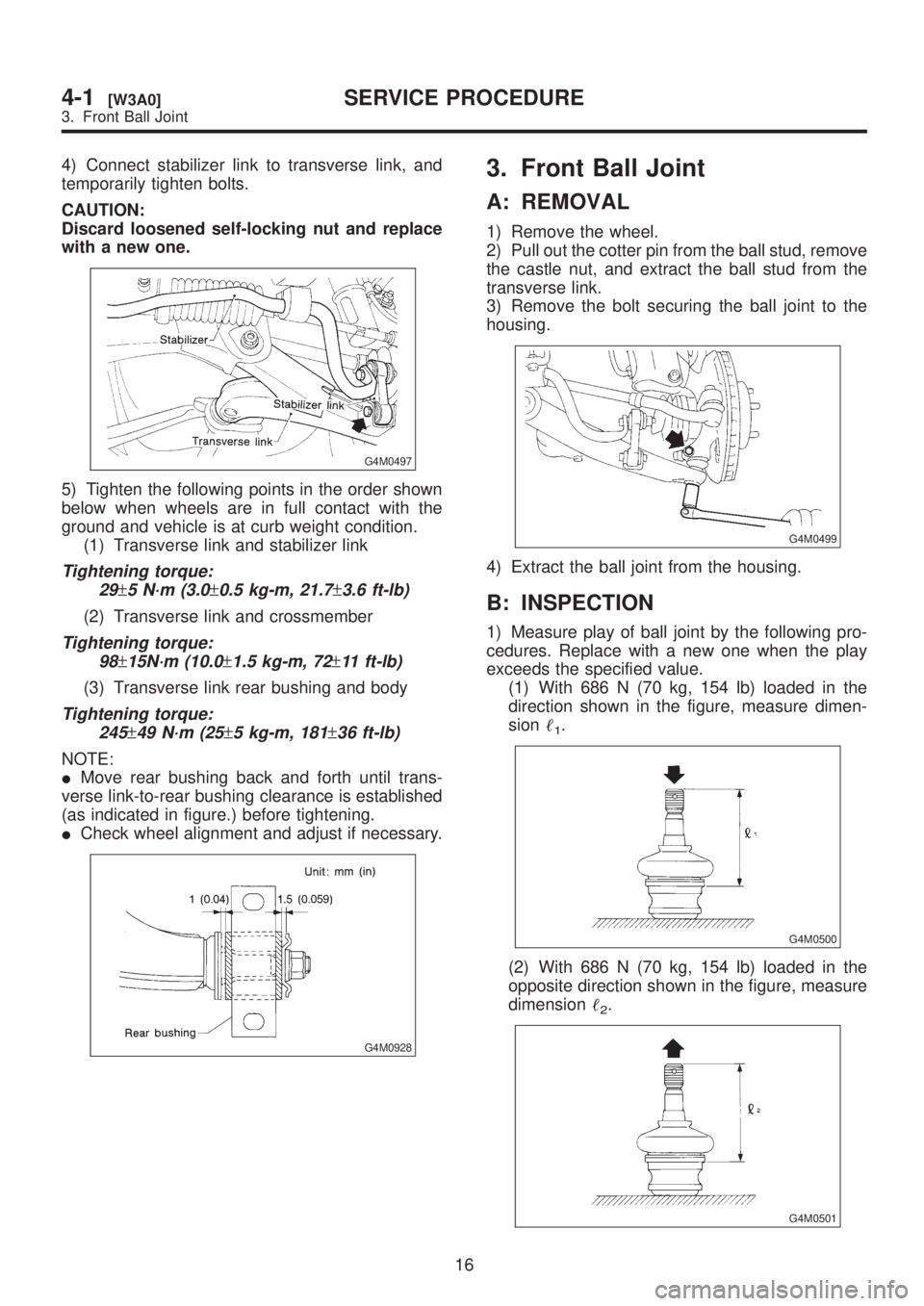
4) Connect stabilizer link to transverse link, and
temporarily tighten bolts.
CAUTION:
Discard loosened self-locking nut and replace
with a new one.
G4M0497
5) Tighten the following points in the order shown
below when wheels are in full contact with the
ground and vehicle is at curb weight condition.
(1) Transverse link and stabilizer link
Tightening torque:
29
±5 N´m (3.0±0.5 kg-m, 21.7±3.6 ft-lb)
(2) Transverse link and crossmember
Tightening torque:
98
±15N´m (10.0±1.5 kg-m, 72±11 ft-lb)
(3) Transverse link rear bushing and body
Tightening torque:
245
±49 N´m (25±5 kg-m, 181±36 ft-lb)
NOTE:
IMove rear bushing back and forth until trans-
verse link-to-rear bushing clearance is established
(as indicated in figure.) before tightening.
ICheck wheel alignment and adjust if necessary.
G4M0928
3. Front Ball Joint
A: REMOVAL
1) Remove the wheel.
2) Pull out the cotter pin from the ball stud, remove
the castle nut, and extract the ball stud from the
transverse link.
3) Remove the bolt securing the ball joint to the
housing.
G4M0499
4) Extract the ball joint from the housing.
B: INSPECTION
1) Measure play of ball joint by the following pro-
cedures. Replace with a new one when the play
exceeds the specified value.
(1) With 686 N (70 kg, 154 lb) loaded in the
direction shown in the figure, measure dimen-
sion
1.
G4M0500
(2) With 686 N (70 kg, 154 lb) loaded in the
opposite direction shown in the figure, measure
dimension
2.
G4M0501
16
4-1[W3A0]SERVICE PROCEDURE
3. Front Ball Joint
Page 719 of 1456
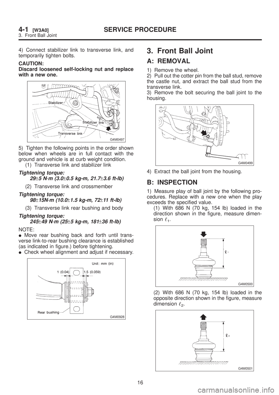
4) Connect stabilizer link to transverse link, and
temporarily tighten bolts.
CAUTION:
Discard loosened self-locking nut and replace
with a new one.
G4M0497
5) Tighten the following points in the order shown
below when wheels are in full contact with the
ground and vehicle is at curb weight condition.
(1) Transverse link and stabilizer link
Tightening torque:
29
±5 N´m (3.0±0.5 kg-m, 21.7±3.6 ft-lb)
(2) Transverse link and crossmember
Tightening torque:
98
±15N´m (10.0±1.5 kg-m, 72±11 ft-lb)
(3) Transverse link rear bushing and body
Tightening torque:
245
±49 N´m (25±5 kg-m, 181±36 ft-lb)
NOTE:
IMove rear bushing back and forth until trans-
verse link-to-rear bushing clearance is established
(as indicated in figure.) before tightening.
ICheck wheel alignment and adjust if necessary.
G4M0928
3. Front Ball Joint
A: REMOVAL
1) Remove the wheel.
2) Pull out the cotter pin from the ball stud, remove
the castle nut, and extract the ball stud from the
transverse link.
3) Remove the bolt securing the ball joint to the
housing.
G4M0499
4) Extract the ball joint from the housing.
B: INSPECTION
1) Measure play of ball joint by the following pro-
cedures. Replace with a new one when the play
exceeds the specified value.
(1) With 686 N (70 kg, 154 lb) loaded in the
direction shown in the figure, measure dimen-
sion
1.
G4M0500
(2) With 686 N (70 kg, 154 lb) loaded in the
opposite direction shown in the figure, measure
dimension
2.
G4M0501
16
4-1[W3A0]SERVICE PROCEDURE
3. Front Ball Joint
Page 720 of 1456
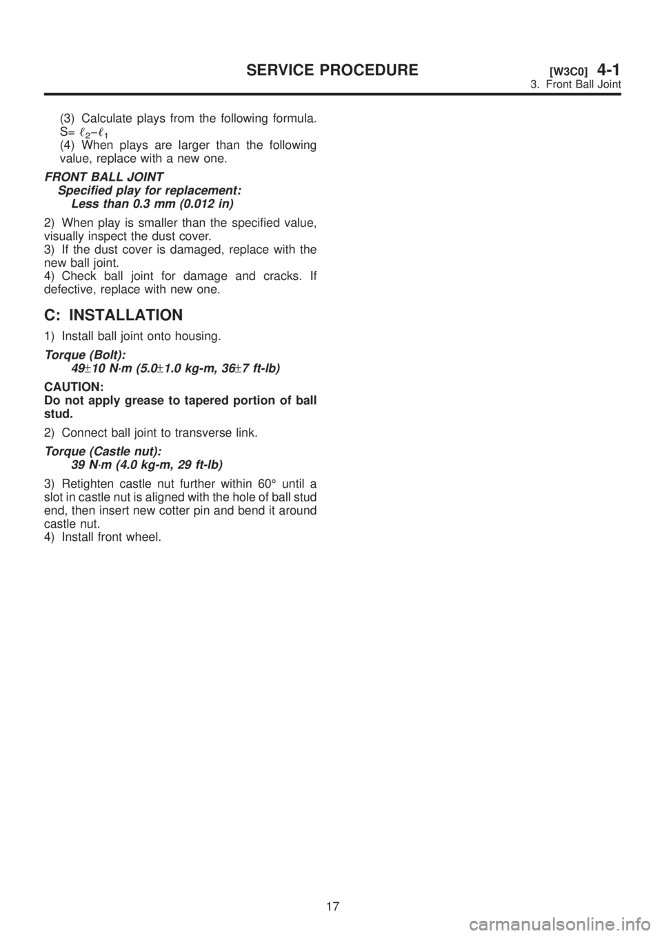
(3) Calculate plays from the following formula.
S=
2þ1(4) When plays are larger than the following
value, replace with a new one.
FRONT BALL JOINT
Specified play for replacement:
Less than 0.3 mm (0.012 in)
2) When play is smaller than the specified value,
visually inspect the dust cover.
3) If the dust cover is damaged, replace with the
new ball joint.
4) Check ball joint for damage and cracks. If
defective, replace with new one.
C: INSTALLATION
1) Install ball joint onto housing.
Torque (Bolt):
49
±10 N´m (5.0±1.0 kg-m, 36±7 ft-lb)
CAUTION:
Do not apply grease to tapered portion of ball
stud.
2) Connect ball joint to transverse link.
Torque (Castle nut):
39 N´m (4.0 kg-m, 29 ft-lb)
3) Retighten castle nut further within 60É until a
slot in castle nut is aligned with the hole of ball stud
end, then insert new cotter pin and bend it around
castle nut.
4) Install front wheel.
17
[W3C0]4-1SERVICE PROCEDURE
3. Front Ball Joint
Page 721 of 1456
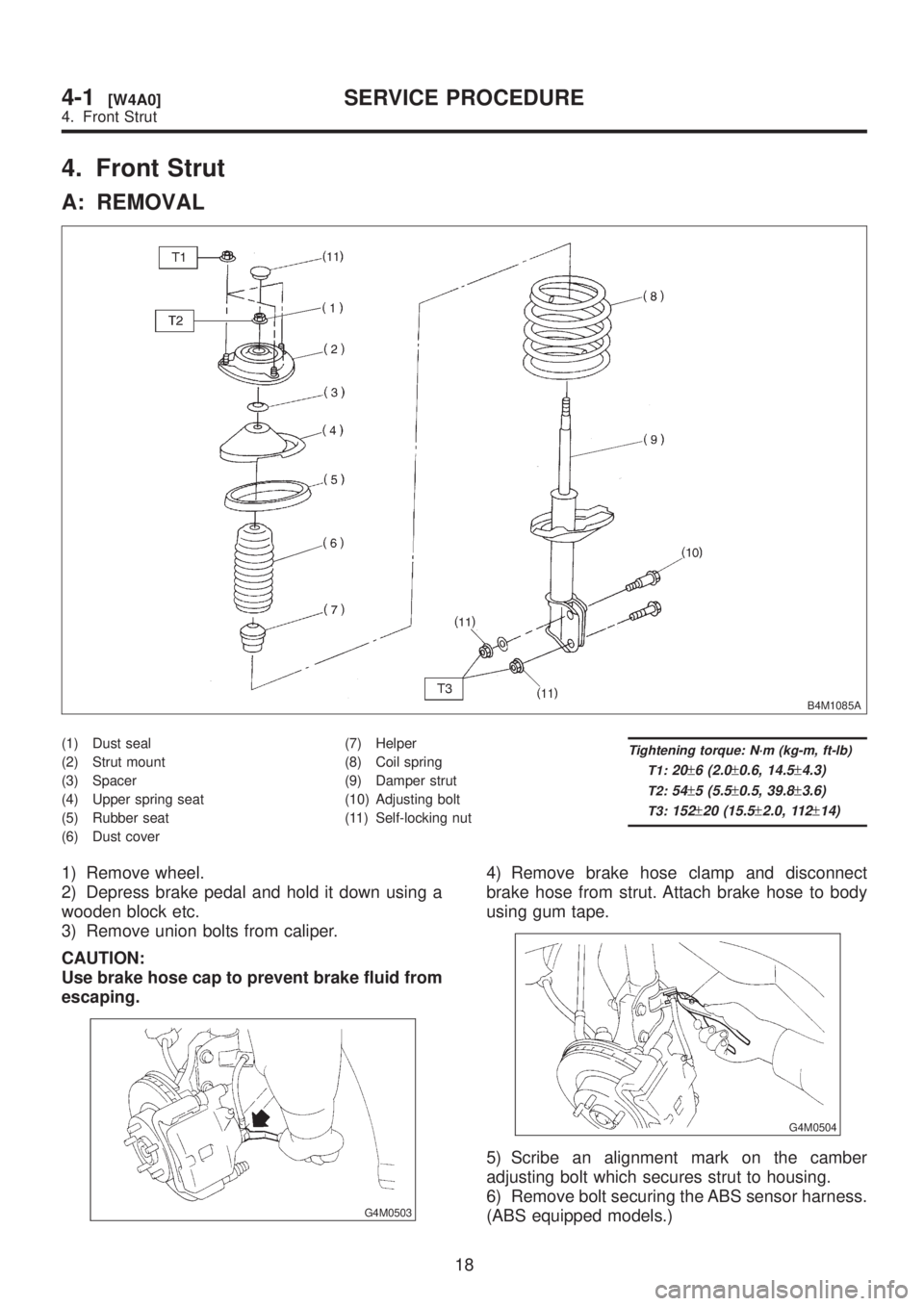
4. Front Strut
A: REMOVAL
B4M1085A
(1) Dust seal
(2) Strut mount
(3) Spacer
(4) Upper spring seat
(5) Rubber seat
(6) Dust cover(7) Helper
(8) Coil spring
(9) Damper strut
(10) Adjusting bolt
(11) Self-locking nutTightening torque: N´m (kg-m, ft-lb)
T1:
20±6 (2.0±0.6, 14.5±4.3)
T2:54±5 (5.5±0.5, 39.8±3.6)
T3:152±20 (15.5±2.0, 112±14)
1) Remove wheel.
2) Depress brake pedal and hold it down using a
wooden block etc.
3) Remove union bolts from caliper.
CAUTION:
Use brake hose cap to prevent brake fluid from
escaping.
G4M0503
4) Remove brake hose clamp and disconnect
brake hose from strut. Attach brake hose to body
using gum tape.
G4M0504
5) Scribe an alignment mark on the camber
adjusting bolt which secures strut to housing.
6) Remove bolt securing the ABS sensor harness.
(ABS equipped models.)
18
4-1[W4A0]SERVICE PROCEDURE
4. Front Strut
Page 724 of 1456
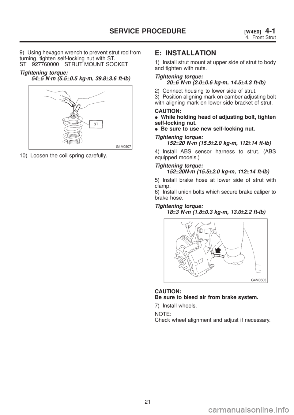
9) Using hexagon wrench to prevent strut rod from
turning, tighten self-locking nut with ST.
ST 927760000 STRUT MOUNT SOCKET
Tightening torque:
54
±5 N´m (5.5±0.5 kg-m, 39.8±3.6 ft-lb)
G4M0507
10) Loosen the coil spring carefully.
E: INSTALLATION
1) Install strut mount at upper side of strut to body
and tighten with nuts.
Tightening torque:
20
±6 N´m (2.0±0.6 kg-m, 14.5±4.3 ft-lb)
2) Connect housing to lower side of strut.
3) Position aligning mark on camber adjusting bolt
with aligning mark on lower side bracket of strut.
CAUTION:
IWhile holding head of adjusting bolt, tighten
self-locking nut.
IBe sure to use new self-locking nut.
Tightening torque:
152
±20 N´m (15.5±2.0 kg-m, 112±14 ft-lb)
4) Install ABS sensor harness to strut. (ABS
equipped models.)
Tightening torque:
152
±20N´m (15.5±2.0 kg-m, 112±14 ft-lb)
5) Install brake hose at lower side of strut with
clamp.
6) Install union bolts which secure brake caliper to
brake hose.
Tightening torque:
18
±3 N´m (1.8±0.3 kg-m, 13.0±2.2 ft-lb)
G4M0503
CAUTION:
Be sure to bleed air from brake system.
7) Install wheels.
NOTE:
Check wheel alignment and adjust if necessary.
21
[W4E0]4-1SERVICE PROCEDURE
4. Front Strut
Page 726 of 1456
B: INSPECTION
1) Check bushing for cracks, fatigue or damage.
2) Check stabilizer link for deformities, cracks, or
damage, and bushing for protrusions from the hole
of stabilizer link and its play.
C: INSTALLATION
1) To install, reverse the removal procedure.
NOTE:
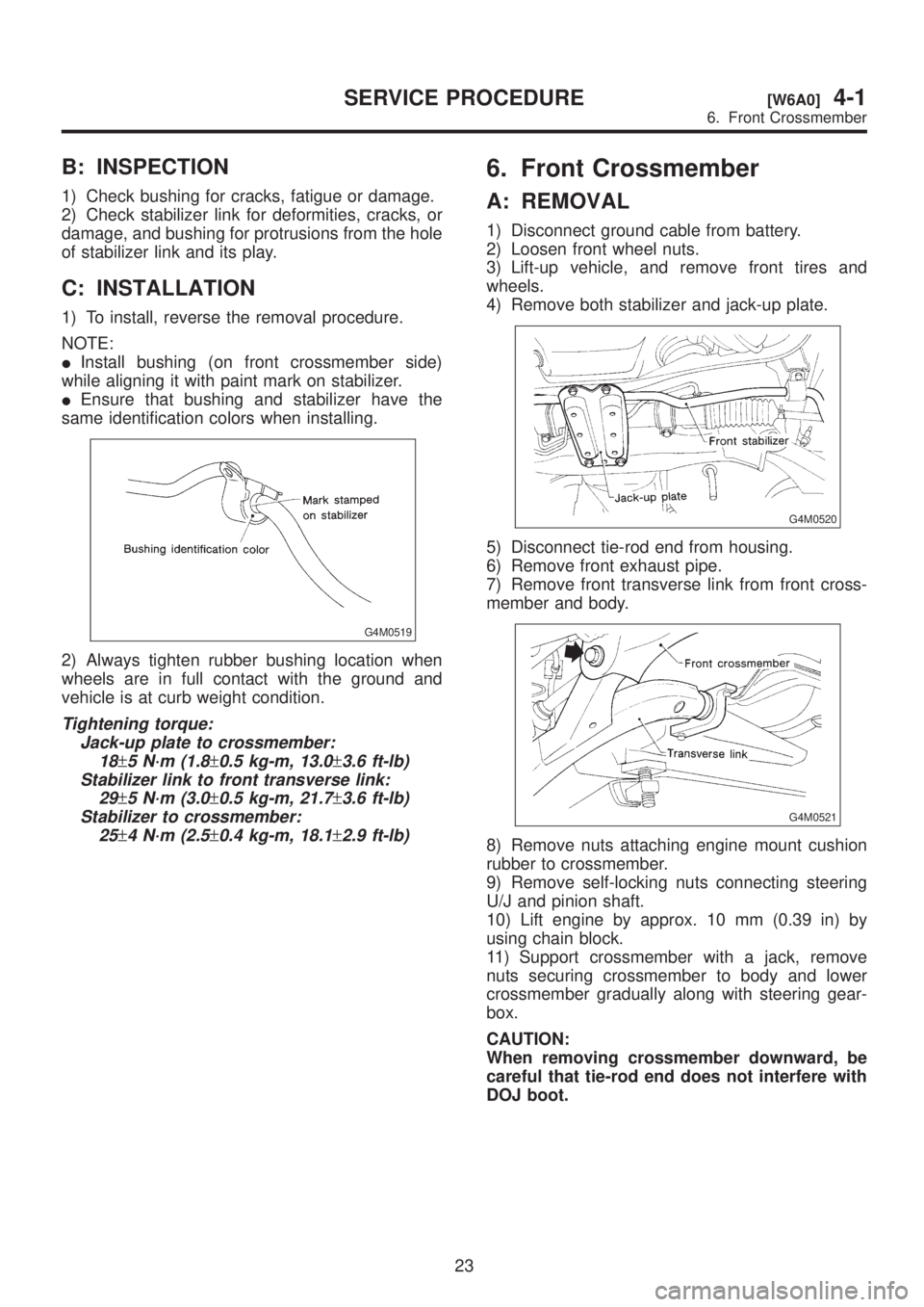
IInstall bushing (on front crossmember side)
while aligning it with paint mark on stabilizer.
IEnsure that bushing and stabilizer have the
same identification colors when installing.
G4M0519
2) Always tighten rubber bushing location when
wheels are in full contact with the ground and
vehicle is at curb weight condition.
Tightening torque:
Jack-up plate to crossmember:
18
±5 N´m (1.8±0.5 kg-m, 13.0±3.6 ft-lb)
Stabilizer link to front transverse link:
29
±5 N´m (3.0±0.5 kg-m, 21.7±3.6 ft-lb)
Stabilizer to crossmember:
25
±4 N´m (2.5±0.4 kg-m, 18.1±2.9 ft-lb)
6. Front Crossmember
A: REMOVAL
1) Disconnect ground cable from battery.
2) Loosen front wheel nuts.
3) Lift-up vehicle, and remove front tires and
wheels.
4) Remove both stabilizer and jack-up plate.
G4M0520
5) Disconnect tie-rod end from housing.
6) Remove front exhaust pipe.
7) Remove front transverse link from front cross-
member and body.
G4M0521
8) Remove nuts attaching engine mount cushion
rubber to crossmember.
9) Remove self-locking nuts connecting steering
U/J and pinion shaft.
10) Lift engine by approx. 10 mm (0.39 in) by
using chain block.
11) Support crossmember with a jack, remove
nuts securing crossmember to body and lower
crossmember gradually along with steering gear-
box.
CAUTION:
When removing crossmember downward, be
careful that tie-rod end does not interfere with
DOJ boot.
23
[W6A0]4-1SERVICE PROCEDURE
6. Front Crossmember