wheel SUBARU LEGACY 1999 Service Manual PDF
[x] Cancel search | Manufacturer: SUBARU, Model Year: 1999, Model line: LEGACY, Model: SUBARU LEGACY 1999Pages: 1456, PDF Size: 59.93 MB
Page 744 of 1456
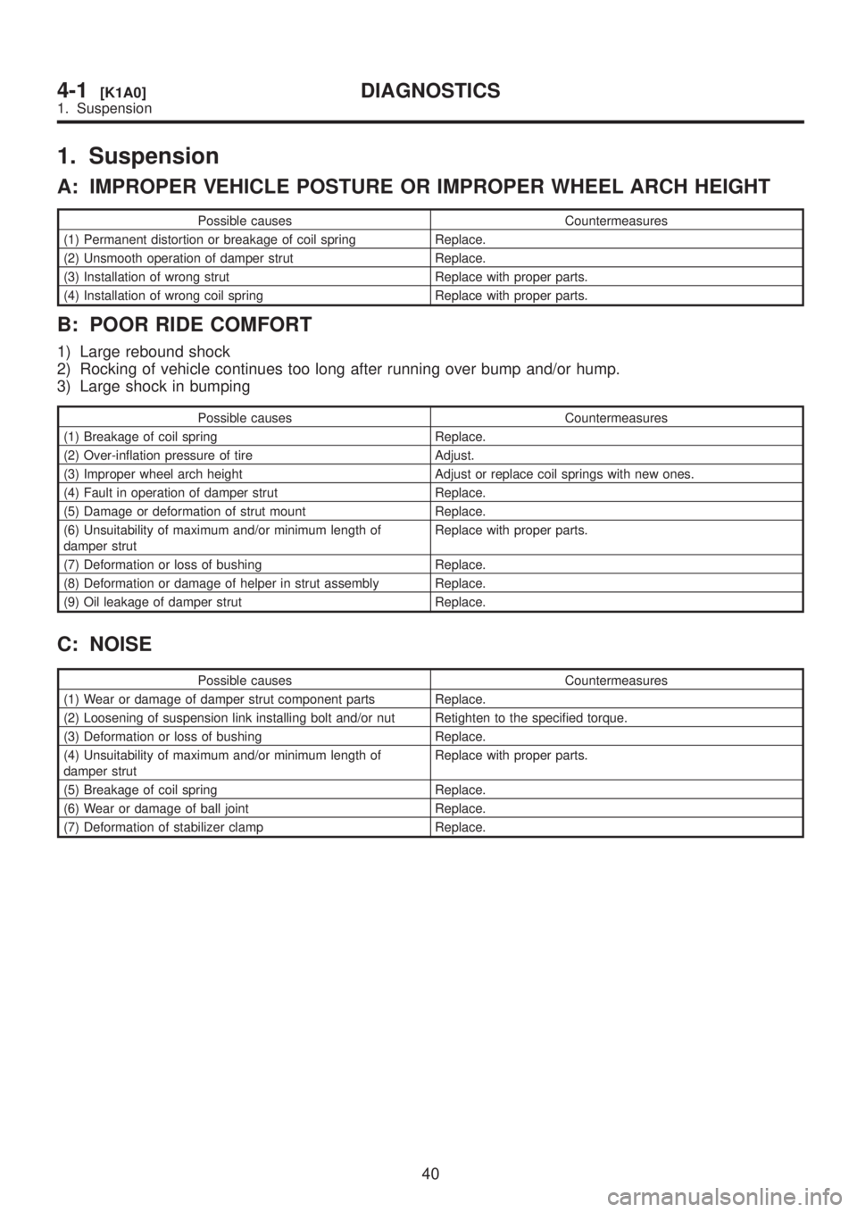
1. Suspension
A: IMPROPER VEHICLE POSTURE OR IMPROPER WHEEL ARCH HEIGHT
Possible causes Countermeasures
(1) Permanent distortion or breakage of coil spring Replace.
(2) Unsmooth operation of damper strut Replace.
(3) Installation of wrong strut Replace with proper parts.
(4) Installation of wrong coil spring Replace with proper parts.
B: POOR RIDE COMFORT
1) Large rebound shock
2) Rocking of vehicle continues too long after running over bump and/or hump.
3) Large shock in bumping
Possible causes Countermeasures
(1) Breakage of coil spring Replace.
(2) Over-inflation pressure of tire Adjust.
(3) Improper wheel arch height Adjust or replace coil springs with new ones.
(4) Fault in operation of damper strut Replace.
(5) Damage or deformation of strut mount Replace.
(6) Unsuitability of maximum and/or minimum length of
damper strutReplace with proper parts.
(7) Deformation or loss of bushing Replace.
(8) Deformation or damage of helper in strut assembly Replace.
(9) Oil leakage of damper strut Replace.
C: NOISE
Possible causes Countermeasures
(1) Wear or damage of damper strut component parts Replace.
(2) Loosening of suspension link installing bolt and/or nut Retighten to the specified torque.
(3) Deformation or loss of bushing Replace.
(4) Unsuitability of maximum and/or minimum length of
damper strutReplace with proper parts.
(5) Breakage of coil spring Replace.
(6) Wear or damage of ball joint Replace.
(7) Deformation of stabilizer clamp Replace.
40
4-1[K1A0]DIAGNOSTICS
1. Suspension
Page 745 of 1456
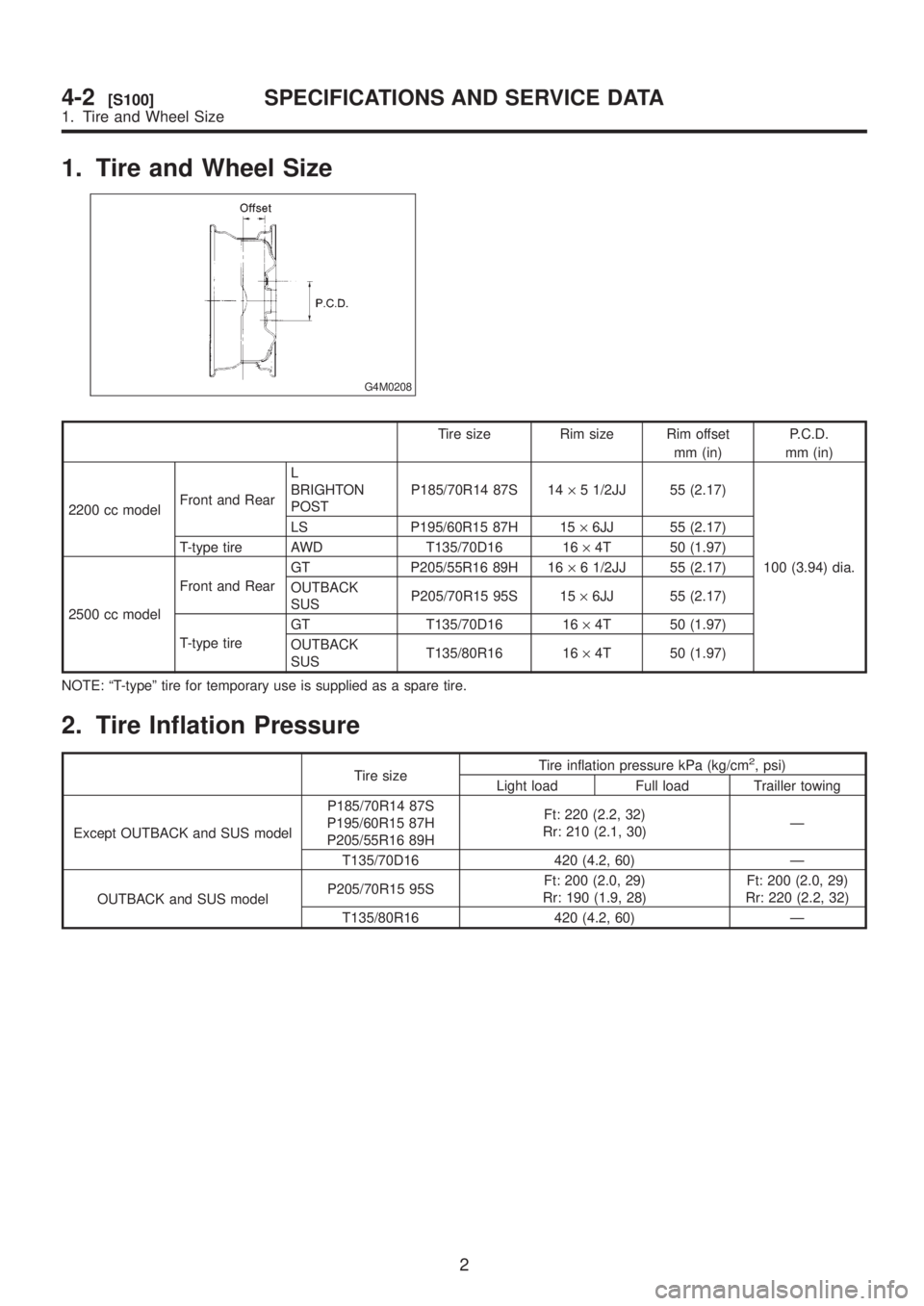
1. Tire and Wheel Size
G4M0208
Tire size Rim size Rim offset
mm (in)P.C.D.
mm (in)
2200 cc modelFront and RearL
BRIGHTON
POSTP185/70R14 87S 14´5 1/2JJ 55 (2.17)
100 (3.94) dia. LS P195/60R15 87H 15´6JJ 55 (2.17)
T-type tire AWD T135/70D16 16´4T 50 (1.97)
2500 cc modelFront and RearGT P205/55R16 89H 16´6 1/2JJ 55 (2.17)
OUTBACK
SUSP205/70R15 95S 15´6JJ 55 (2.17)
T-type tireGT T135/70D16 16´4T 50 (1.97)
OUTBACK
SUST135/80R16 16´4T 50 (1.97)
NOTE: ªT-typeº tire for temporary use is supplied as a spare tire.
2. Tire Inflation Pressure
Tire sizeTire inflation pressure kPa (kg/cm
2, psi)
Light load Full load Trailler towing
Except OUTBACK and SUS modelP185/70R14 87S
P195/60R15 87H
P205/55R16 89HFt: 220 (2.2, 32)
Rr: 210 (2.1, 30)Ð
T135/70D16 420 (4.2, 60) Ð
OUTBACK and SUS modelP205/70R15 95SFt: 200 (2.0, 29)
Rr: 190 (1.9, 28)Ft: 200 (2.0, 29)
Rr: 220 (2.2, 32)
T135/80R16 420 (4.2, 60) Ð
2
4-2[S100]SPECIFICATIONS AND SERVICE DATA
1. Tire and Wheel Size
Page 746 of 1456
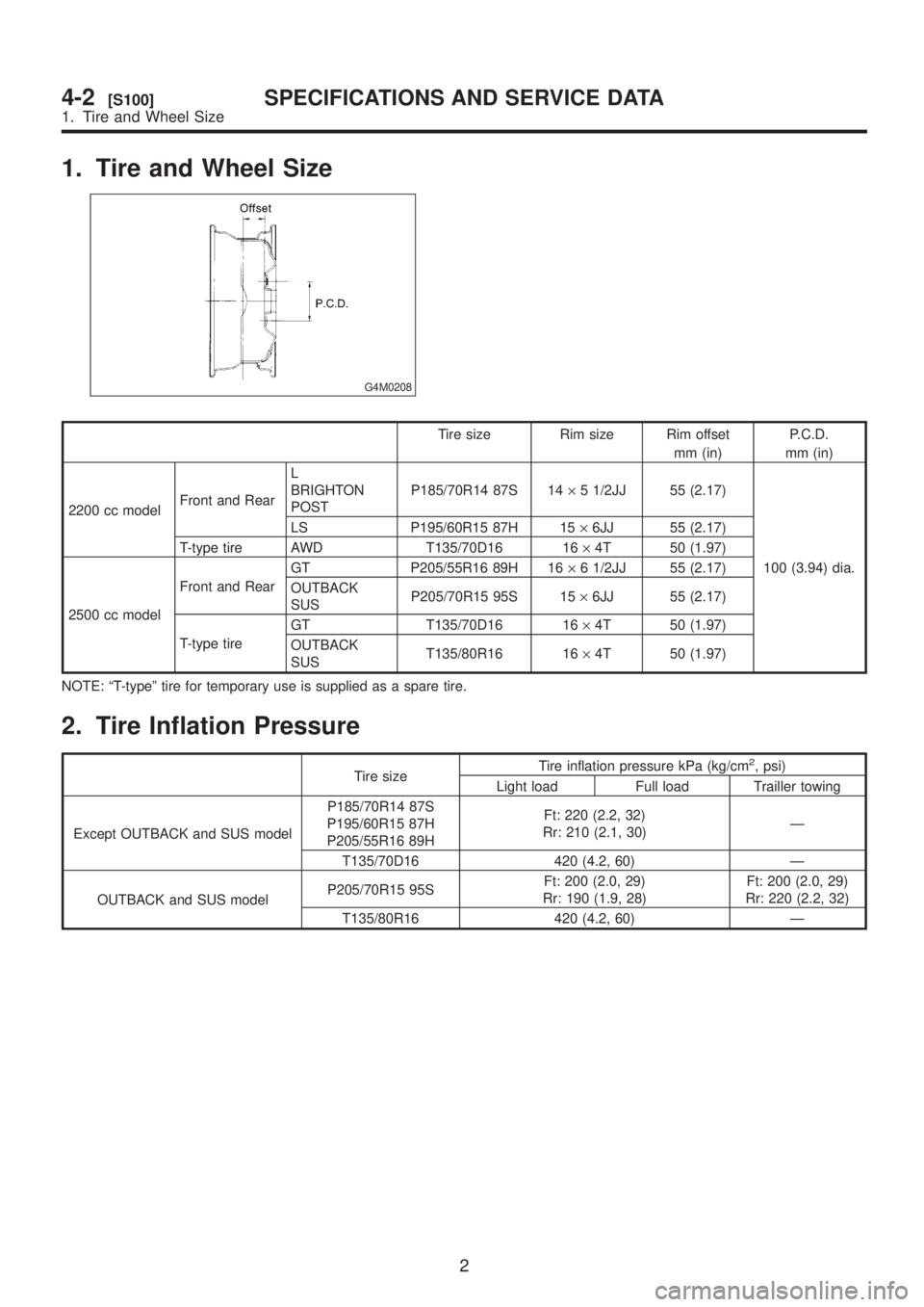
1. Tire and Wheel Size
G4M0208
Tire size Rim size Rim offset
mm (in)P.C.D.
mm (in)
2200 cc modelFront and RearL
BRIGHTON
POSTP185/70R14 87S 14´5 1/2JJ 55 (2.17)
100 (3.94) dia. LS P195/60R15 87H 15´6JJ 55 (2.17)
T-type tire AWD T135/70D16 16´4T 50 (1.97)
2500 cc modelFront and RearGT P205/55R16 89H 16´6 1/2JJ 55 (2.17)
OUTBACK
SUSP205/70R15 95S 15´6JJ 55 (2.17)
T-type tireGT T135/70D16 16´4T 50 (1.97)
OUTBACK
SUST135/80R16 16´4T 50 (1.97)
NOTE: ªT-typeº tire for temporary use is supplied as a spare tire.
2. Tire Inflation Pressure
Tire sizeTire inflation pressure kPa (kg/cm
2, psi)
Light load Full load Trailler towing
Except OUTBACK and SUS modelP185/70R14 87S
P195/60R15 87H
P205/55R16 89HFt: 220 (2.2, 32)
Rr: 210 (2.1, 30)Ð
T135/70D16 420 (4.2, 60) Ð
OUTBACK and SUS modelP205/70R15 95SFt: 200 (2.0, 29)
Rr: 190 (1.9, 28)Ft: 200 (2.0, 29)
Rr: 220 (2.2, 32)
T135/80R16 420 (4.2, 60) Ð
2
4-2[S100]SPECIFICATIONS AND SERVICE DATA
1. Tire and Wheel Size
Page 750 of 1456
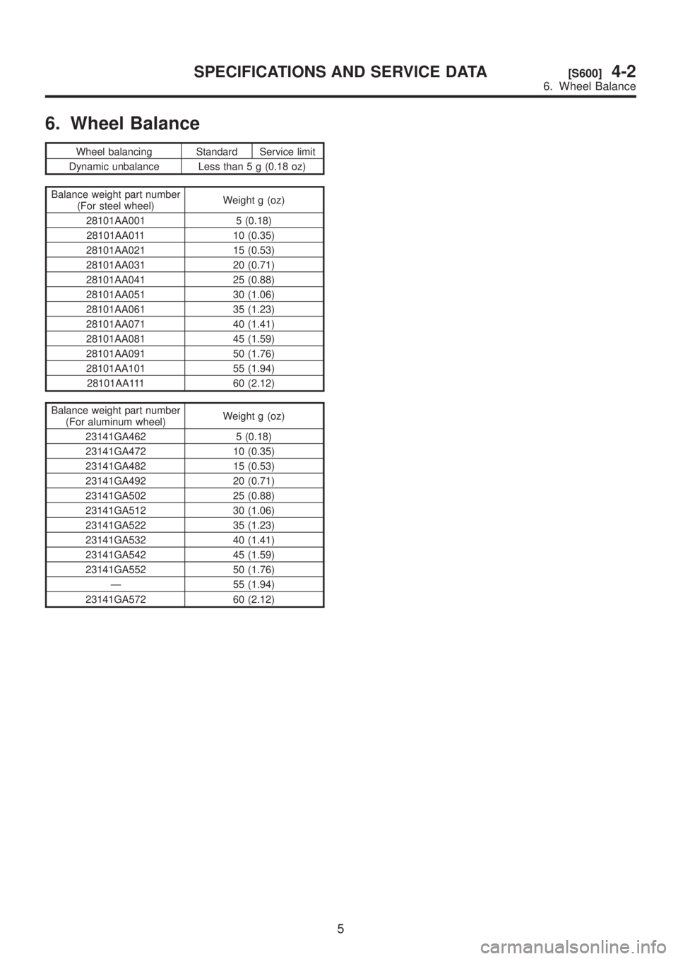
6. Wheel Balance
Wheel balancing Standard Service limit
Dynamic unbalance Less than 5 g (0.18 oz)
Balance weight part number
(For steel wheel)Weight g (oz)
28101AA001 5 (0.18)
28101AA011 10 (0.35)
28101AA021 15 (0.53)
28101AA031 20 (0.71)
28101AA041 25 (0.88)
28101AA051 30 (1.06)
28101AA061 35 (1.23)
28101AA071 40 (1.41)
28101AA081 45 (1.59)
28101AA091 50 (1.76)
28101AA101 55 (1.94)
28101AA111 60 (2.12)
Balance weight part number
(For aluminum wheel)Weight g (oz)
23141GA462 5 (0.18)
23141GA472 10 (0.35)
23141GA482 15 (0.53)
23141GA492 20 (0.71)
23141GA502 25 (0.88)
23141GA512 30 (1.06)
23141GA522 35 (1.23)
23141GA532 40 (1.41)
23141GA542 45 (1.59)
23141GA552 50 (1.76)
Ð 55 (1.94)
23141GA572 60 (2.12)
5
[S600]4-2SPECIFICATIONS AND SERVICE DATA
6. Wheel Balance
Page 751 of 1456
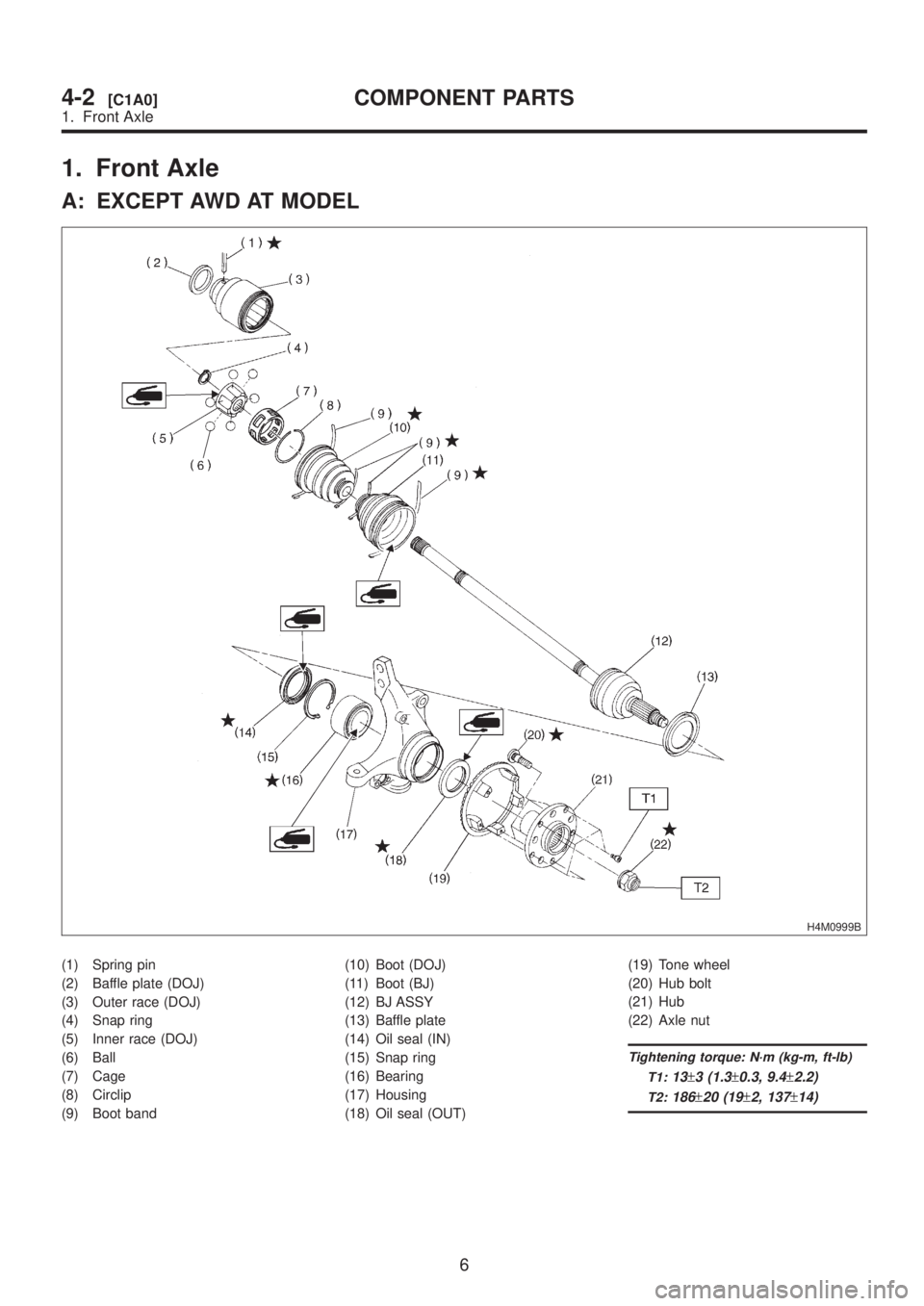
1. Front Axle
A: EXCEPT AWD AT MODEL
H4M0999B
(1) Spring pin
(2) Baffle plate (DOJ)
(3) Outer race (DOJ)
(4) Snap ring
(5) Inner race (DOJ)
(6) Ball
(7) Cage
(8) Circlip
(9) Boot band(10) Boot (DOJ)
(11) Boot (BJ)
(12) BJ ASSY
(13) Baffle plate
(14) Oil seal (IN)
(15) Snap ring
(16) Bearing
(17) Housing
(18) Oil seal (OUT)(19) Tone wheel
(20) Hub bolt
(21) Hub
(22) Axle nut
Tightening torque: N´m (kg-m, ft-lb)
T1:
13±3 (1.3±0.3, 9.4±2.2)
T2:186±20 (19±2, 137±14)
6
4-2[C1A0]COMPONENT PARTS
1. Front Axle
Page 752 of 1456
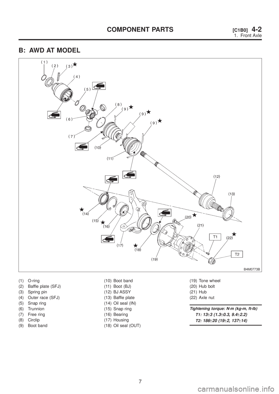
B: AWD AT MODEL
B4M0773B
(1) O-ring
(2) Baffle plate (SFJ)
(3) Spring pin
(4) Outer race (SFJ)
(5) Snap ring
(6) Trunnion
(7) Free ring
(8) Circlip
(9) Boot band(10) Boot band
(11) Boot (BJ)
(12) BJ ASSY
(13) Baffle plate
(14) Oil seal (IN)
(15) Snap ring
(16) Bearing
(17) Housing
(18) Oil seal (OUT)(19) Tone wheel
(20) Hub bolt
(21) Hub
(22) Axle nut
Tightening torque: N´m (kg-m, ft-lb)
T1:
13±3 (1.3±0.3, 9.4±2.2)
T2:186±20 (19±2, 137±14)
7
[C1B0]4-2COMPONENT PARTS
1. Front Axle
Page 753 of 1456
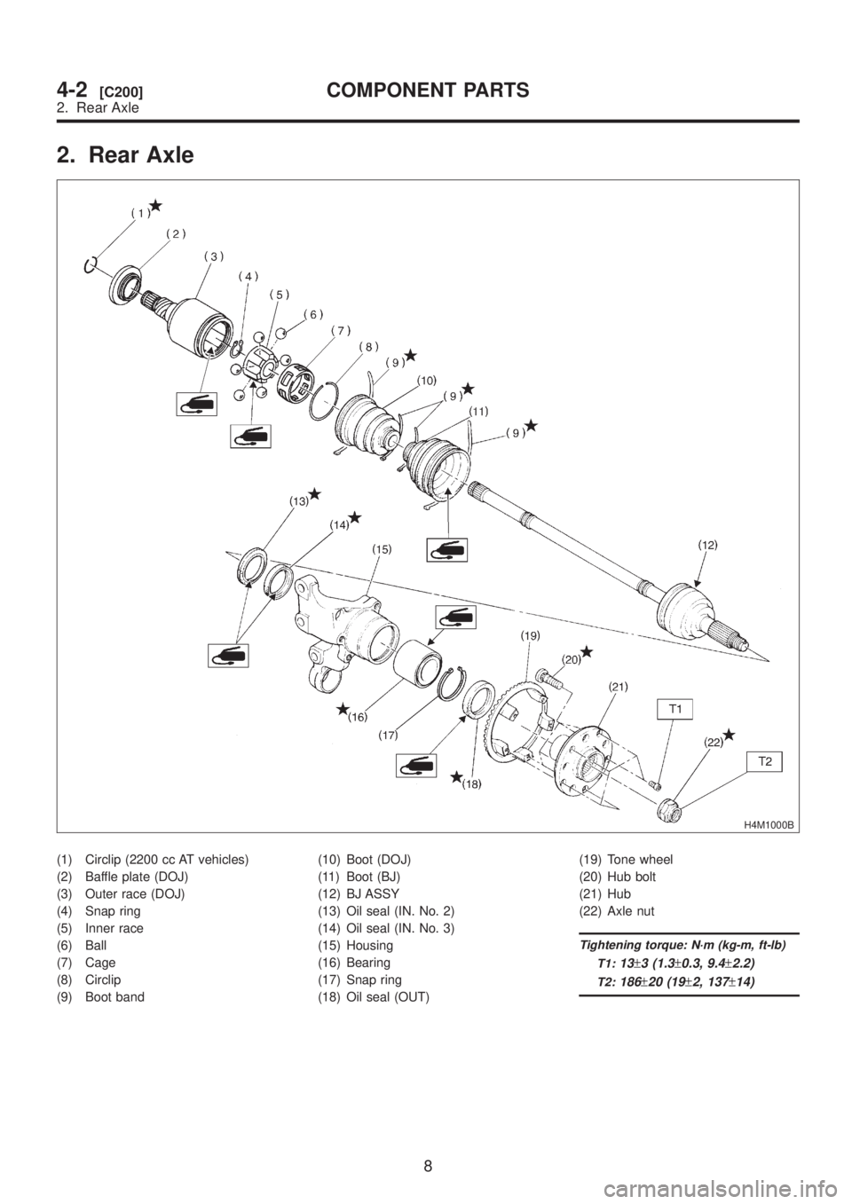
2. Rear Axle
H4M1000B
(1) Circlip (2200 cc AT vehicles)
(2) Baffle plate (DOJ)
(3) Outer race (DOJ)
(4) Snap ring
(5) Inner race
(6) Ball
(7) Cage
(8) Circlip
(9) Boot band(10) Boot (DOJ)
(11) Boot (BJ)
(12) BJ ASSY
(13) Oil seal (IN. No. 2)
(14) Oil seal (IN. No. 3)
(15) Housing
(16) Bearing
(17) Snap ring
(18) Oil seal (OUT)(19) Tone wheel
(20) Hub bolt
(21) Hub
(22) Axle nut
Tightening torque: N´m (kg-m, ft-lb)
T1:
13±3 (1.3±0.3, 9.4±2.2)
T2:186±20 (19±2, 137±14)
8
4-2[C200]COMPONENT PARTS
2. Rear Axle
Page 754 of 1456
1. Front Axle
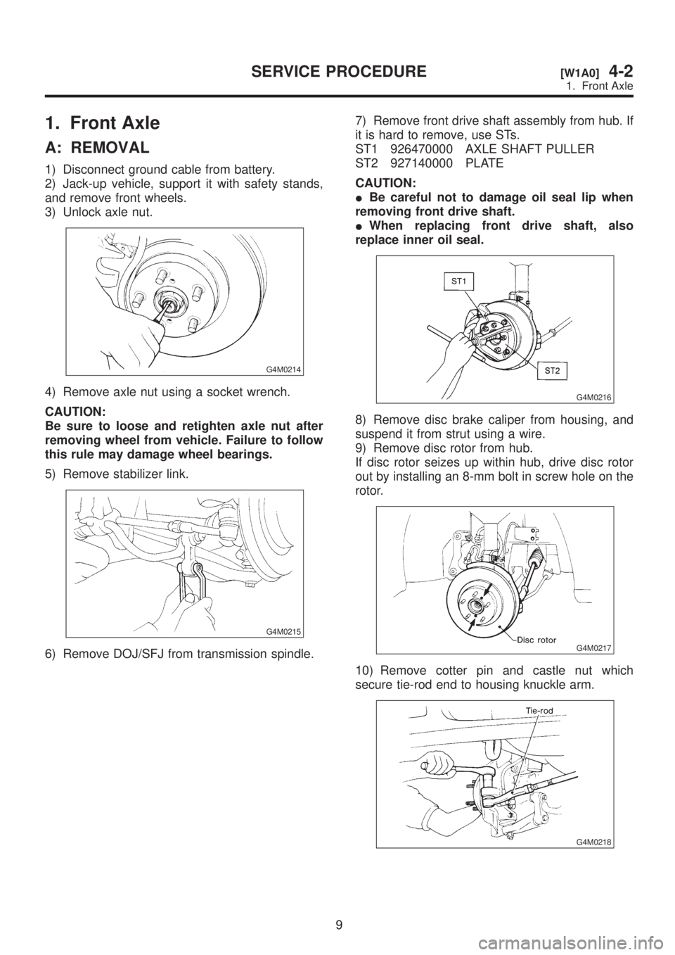
A: REMOVAL
1) Disconnect ground cable from battery.
2) Jack-up vehicle, support it with safety stands,
and remove front wheels.
3) Unlock axle nut.
G4M0214
4) Remove axle nut using a socket wrench.
CAUTION:
Be sure to loose and retighten axle nut after
removing wheel from vehicle. Failure to follow
this rule may damage wheel bearings.
5) Remove stabilizer link.
G4M0215
6) Remove DOJ/SFJ from transmission spindle.7) Remove front drive shaft assembly from hub. If
it is hard to remove, use STs.
ST1 926470000 AXLE SHAFT PULLER
ST2 927140000 PLATE
CAUTION:
IBe careful not to damage oil seal lip when
removing front drive shaft.
IWhen replacing front drive shaft, also
replace inner oil seal.
G4M0216
8) Remove disc brake caliper from housing, and
suspend it from strut using a wire.
9) Remove disc rotor from hub.
If disc rotor seizes up within hub, drive disc rotor
out by installing an 8-mm bolt in screw hole on the
rotor.
G4M0217
10) Remove cotter pin and castle nut which
secure tie-rod end to housing knuckle arm.
G4M0218
9
[W1A0]4-2SERVICE PROCEDURE
1. Front Axle
Page 756 of 1456
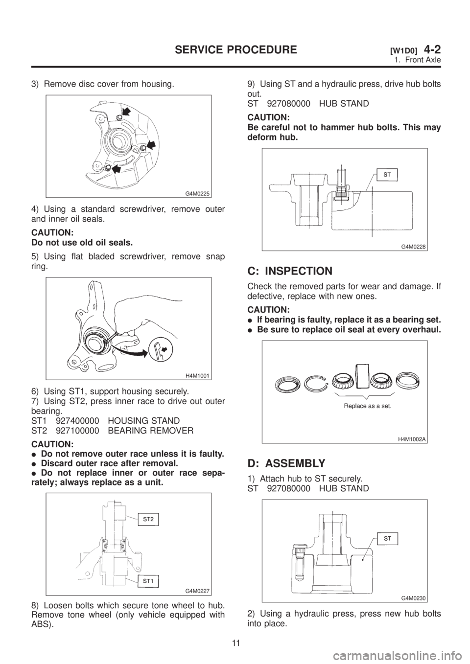
3) Remove disc cover from housing.
G4M0225
4) Using a standard screwdriver, remove outer
and inner oil seals.
CAUTION:
Do not use old oil seals.
5) Using flat bladed screwdriver, remove snap
ring.
H4M1001
6) Using ST1, support housing securely.
7) Using ST2, press inner race to drive out outer
bearing.
ST1 927400000 HOUSING STAND
ST2 927100000 BEARING REMOVER
CAUTION:
IDo not remove outer race unless it is faulty.
IDiscard outer race after removal.
IDo not replace inner or outer race sepa-
rately; always replace as a unit.
G4M0227
8) Loosen bolts which secure tone wheel to hub.
Remove tone wheel (only vehicle equipped with
ABS).9) Using ST and a hydraulic press, drive hub bolts
out.
ST 927080000 HUB STAND
CAUTION:
Be careful not to hammer hub bolts. This may
deform hub.
G4M0228
C: INSPECTION
Check the removed parts for wear and damage. If
defective, replace with new ones.
CAUTION:
IIf bearing is faulty, replace it as a bearing set.
IBe sure to replace oil seal at every overhaul.
H4M1002A
D: ASSEMBLY
1) Attach hub to ST securely.
ST 927080000 HUB STAND
G4M0230
2) Using a hydraulic press, press new hub bolts
into place.
11
[W1D0]4-2SERVICE PROCEDURE
1. Front Axle
Page 757 of 1456
CAUTION:
Be sure to press hub bolts until their seating
surfaces contact the hub.
NOTE:
Use 12 mm (0.47 in) dia. holes in HUB STAND to
prevent bolts from tilting.
3) Remove foreign particles (dust, rust, etc.) from
mating surfaces of hub and tone wheel, and install
tone wheel to hub (only vehicle equipped with
ABS).
CAUTION:
IBe careful not to damage tone wheel teeth.
IEnsure tone wheel closely contacts hub.
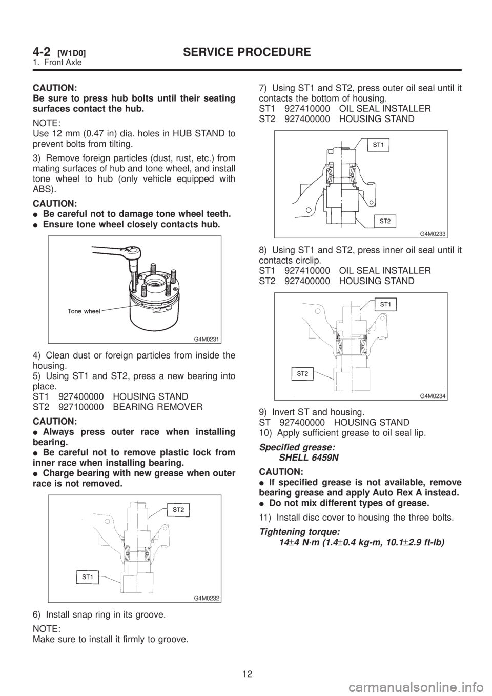
G4M0231
4) Clean dust or foreign particles from inside the
housing.
5) Using ST1 and ST2, press a new bearing into
place.
ST1 927400000 HOUSING STAND
ST2 927100000 BEARING REMOVER
CAUTION:
IAlways press outer race when installing
bearing.
IBe careful not to remove plastic lock from
inner race when installing bearing.
ICharge bearing with new grease when outer
race is not removed.
G4M0232
6) Install snap ring in its groove.
NOTE:
Make sure to install it firmly to groove.7) Using ST1 and ST2, press outer oil seal until it
contacts the bottom of housing.
ST1 927410000 OIL SEAL INSTALLER
ST2 927400000 HOUSING STAND
G4M0233
8) Using ST1 and ST2, press inner oil seal until it
contacts circlip.
ST1 927410000 OIL SEAL INSTALLER
ST2 927400000 HOUSING STAND
G4M0234
9) Invert ST and housing.
ST 927400000 HOUSING STAND
10) Apply sufficient grease to oil seal lip.
Specified grease:
SHELL 6459N
CAUTION:
IIf specified grease is not available, remove
bearing grease and apply Auto Rex A instead.
IDo not mix different types of grease.
11) Install disc cover to housing the three bolts.
Tightening torque:
14
±4 N´m (1.4±0.4 kg-m, 10.1±2.9 ft-lb)
12
4-2[W1D0]SERVICE PROCEDURE
1. Front Axle