wheel SUBARU LEGACY 1999 Service Manual Online
[x] Cancel search | Manufacturer: SUBARU, Model Year: 1999, Model line: LEGACY, Model: SUBARU LEGACY 1999Pages: 1456, PDF Size: 59.93 MB
Page 758 of 1456
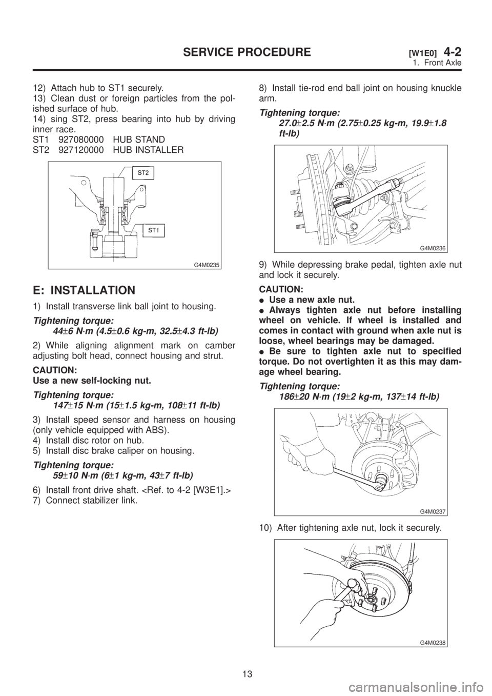
12) Attach hub to ST1 securely.
13) Clean dust or foreign particles from the pol-
ished surface of hub.
14) sing ST2, press bearing into hub by driving
inner race.
ST1 927080000 HUB STAND
ST2 927120000 HUB INSTALLER
G4M0235
E: INSTALLATION
1) Install transverse link ball joint to housing.
Tightening torque:
44
±6 N´m (4.5±0.6 kg-m, 32.5±4.3 ft-lb)
2) While aligning alignment mark on camber
adjusting bolt head, connect housing and strut.
CAUTION:
Use a new self-locking nut.
Tightening torque:
147
±15 N´m (15±1.5 kg-m, 108±11 ft-lb)
3) Install speed sensor and harness on housing
(only vehicle equipped with ABS).
4) Install disc rotor on hub.
5) Install disc brake caliper on housing.
Tightening torque:
59
±10 N´m (6±1 kg-m, 43±7 ft-lb)
6) Install front drive shaft.
7) Connect stabilizer link.8) Install tie-rod end ball joint on housing knuckle
arm.
Tightening torque:
27.0
±2.5 N´m (2.75±0.25 kg-m, 19.9±1.8
ft-lb)
G4M0236
9) While depressing brake pedal, tighten axle nut
and lock it securely.
CAUTION:
IUse a new axle nut.
IAlways tighten axle nut before installing
wheel on vehicle. If wheel is installed and
comes in contact with ground when axle nut is
loose, wheel bearings may be damaged.
IBe sure to tighten axle nut to specified
torque. Do not overtighten it as this may dam-
age wheel bearing.
Tightening torque:
186
±20 N´m (19±2 kg-m, 137±14 ft-lb)
G4M0237
10) After tightening axle nut, lock it securely.
G4M0238
13
[W1E0]4-2SERVICE PROCEDURE
1. Front Axle
Page 759 of 1456
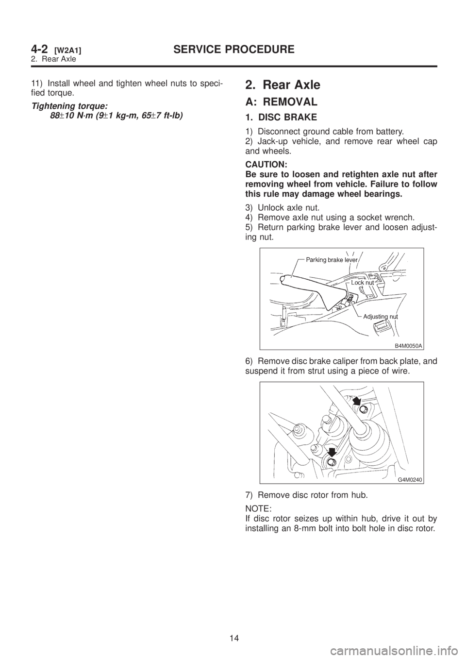
11) Install wheel and tighten wheel nuts to speci-
fied torque.
Tightening torque:
88
±10 N´m (9±1 kg-m, 65±7 ft-lb)
2. Rear Axle
A: REMOVAL
1. DISC BRAKE
1) Disconnect ground cable from battery.
2) Jack-up vehicle, and remove rear wheel cap
and wheels.
CAUTION:
Be sure to loosen and retighten axle nut after
removing wheel from vehicle. Failure to follow
this rule may damage wheel bearings.
3) Unlock axle nut.
4) Remove axle nut using a socket wrench.
5) Return parking brake lever and loosen adjust-
ing nut.
B4M0050A
6) Remove disc brake caliper from back plate, and
suspend it from strut using a piece of wire.
G4M0240
7) Remove disc rotor from hub.
NOTE:
If disc rotor seizes up within hub, drive it out by
installing an 8-mm bolt into bolt hole in disc rotor.
14
4-2[W2A1]SERVICE PROCEDURE
2. Rear Axle
Page 760 of 1456
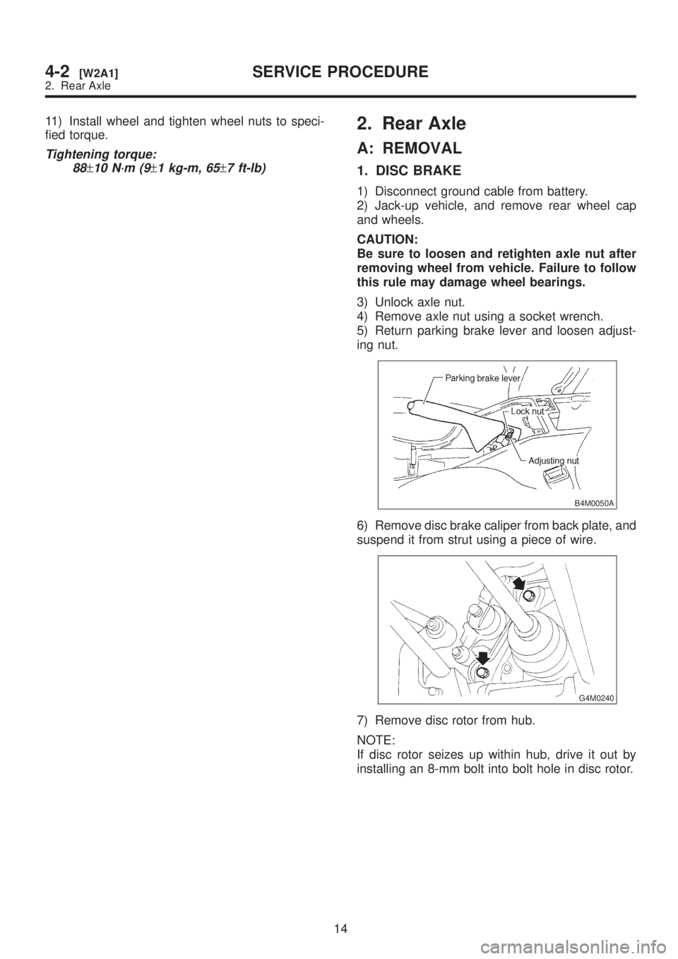
11) Install wheel and tighten wheel nuts to speci-
fied torque.
Tightening torque:
88
±10 N´m (9±1 kg-m, 65±7 ft-lb)
2. Rear Axle
A: REMOVAL
1. DISC BRAKE
1) Disconnect ground cable from battery.
2) Jack-up vehicle, and remove rear wheel cap
and wheels.
CAUTION:
Be sure to loosen and retighten axle nut after
removing wheel from vehicle. Failure to follow
this rule may damage wheel bearings.
3) Unlock axle nut.
4) Remove axle nut using a socket wrench.
5) Return parking brake lever and loosen adjust-
ing nut.
B4M0050A
6) Remove disc brake caliper from back plate, and
suspend it from strut using a piece of wire.
G4M0240
7) Remove disc rotor from hub.
NOTE:
If disc rotor seizes up within hub, drive it out by
installing an 8-mm bolt into bolt hole in disc rotor.
14
4-2[W2A1]SERVICE PROCEDURE
2. Rear Axle
Page 761 of 1456
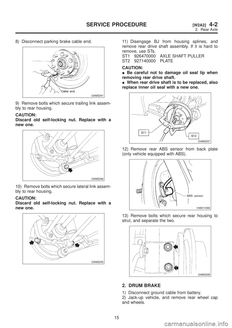
8) Disconnect parking brake cable end.
G4M0241
9) Remove bolts which secure trailing link assem-
bly to rear housing.
CAUTION:
Discard old self-locking nut. Replace with a
new one.
G4M0246
10) Remove bolts which secure lateral link assem-
bly to rear housing.
CAUTION:
Discard old self-locking nut. Replace with a
new one.
G4M0245
11) Disengage BJ from housing splines, and
remove rear drive shaft assembly. If it is hard to
remove, use STs.
ST1 926470000 AXLE SHAFT PULLER
ST2 927140000 PLATE
CAUTION:
IBe careful not to damage oil seal lip when
removing rear drive shaft.
IWhen rear drive shaft is to be replaced, also
replace inner oil seal with a new one.
G4M0247
12) Remove rear ABS sensor from back plate
(only vehicle equipped with ABS).
H4M1139A
13) Remove bolts which secure rear housing to
strut, and separate the two.
G4M0249
2. DRUM BRAKE
1) Disconnect ground cable from battery.
2) Jack-up vehicle, and remove rear wheel cap
and wheels.
15
[W2A2]4-2SERVICE PROCEDURE
2. Rear Axle
Page 762 of 1456
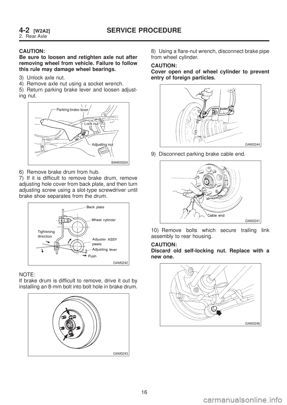
CAUTION:
Be sure to loosen and retighten axle nut after
removing wheel from vehicle. Failure to follow
this rule may damage wheel bearings.
3) Unlock axle nut.
4) Remove axle nut using a socket wrench.
5) Return parking brake lever and loosen adjust-
ing nut.
B4M0050A
6) Remove brake drum from hub.
7) If it is difficult to remove brake drum, remove
adjusting hole cover from back plate, and then turn
adjusting screw using a slot-type screwdriver until
brake shoe separates from the drum.
G4M0242
NOTE:
If brake drum is difficult to remove, drive it out by
installing an 8-mm bolt into bolt hole in brake drum.
G4M0243
8) Using a flare-nut wrench, disconnect brake pipe
from wheel cylinder.
CAUTION:
Cover open end of wheel cylinder to prevent
entry of foreign particles.
G4M0244
9) Disconnect parking brake cable end.
G4M0241
10) Remove bolts which secure trailing link
assembly to rear housing.
CAUTION:
Discard old self-locking nut. Replace with a
new one.
G4M0246
16
4-2[W2A2]SERVICE PROCEDURE
2. Rear Axle
Page 764 of 1456
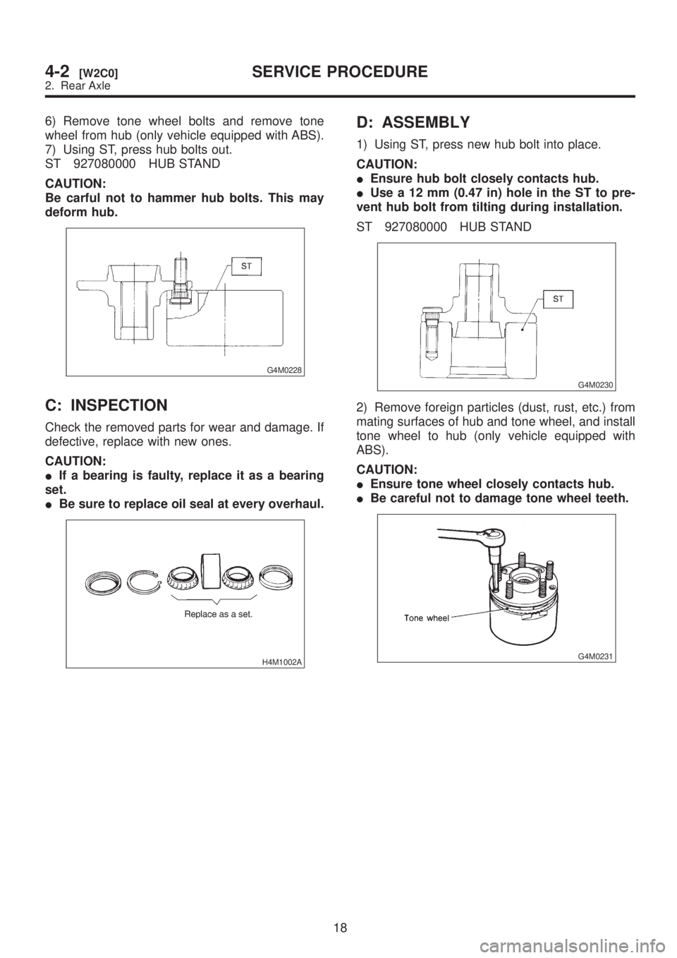
6) Remove tone wheel bolts and remove tone
wheel from hub (only vehicle equipped with ABS).
7) Using ST, press hub bolts out.
ST 927080000 HUB STAND
CAUTION:
Be carful not to hammer hub bolts. This may
deform hub.
G4M0228
C: INSPECTION
Check the removed parts for wear and damage. If
defective, replace with new ones.
CAUTION:
IIf a bearing is faulty, replace it as a bearing
set.
IBe sure to replace oil seal at every overhaul.
H4M1002A
D: ASSEMBLY
1) Using ST, press new hub bolt into place.
CAUTION:
IEnsure hub bolt closely contacts hub.
IUse a 12 mm (0.47 in) hole in the ST to pre-
vent hub bolt from tilting during installation.
ST 927080000 HUB STAND
G4M0230
2) Remove foreign particles (dust, rust, etc.) from
mating surfaces of hub and tone wheel, and install
tone wheel to hub (only vehicle equipped with
ABS).
CAUTION:
IEnsure tone wheel closely contacts hub.
IBe careful not to damage tone wheel teeth.
G4M0231
18
4-2[W2C0]SERVICE PROCEDURE
2. Rear Axle
Page 767 of 1456
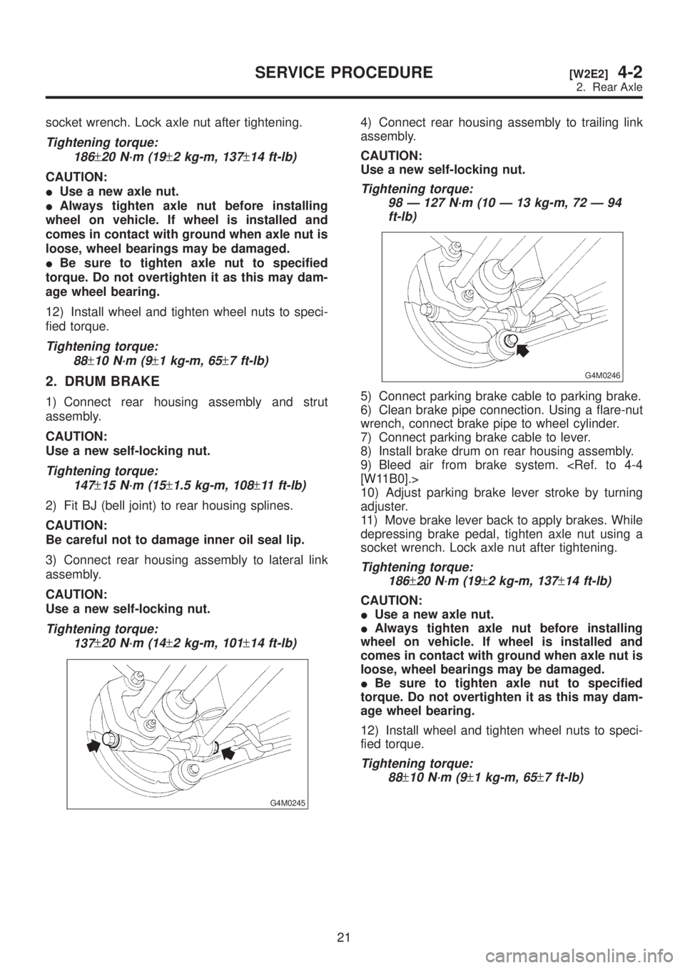
socket wrench. Lock axle nut after tightening.
Tightening torque:
186
±20 N´m (19±2 kg-m, 137±14 ft-lb)
CAUTION:
IUse a new axle nut.
IAlways tighten axle nut before installing
wheel on vehicle. If wheel is installed and
comes in contact with ground when axle nut is
loose, wheel bearings may be damaged.
IBe sure to tighten axle nut to specified
torque. Do not overtighten it as this may dam-
age wheel bearing.
12) Install wheel and tighten wheel nuts to speci-
fied torque.
Tightening torque:
88
±10 N´m (9±1 kg-m, 65±7 ft-lb)
2. DRUM BRAKE
1) Connect rear housing assembly and strut
assembly.
CAUTION:
Use a new self-locking nut.
Tightening torque:
147
±15 N´m (15±1.5 kg-m, 108±11 ft-lb)
2) Fit BJ (bell joint) to rear housing splines.
CAUTION:
Be careful not to damage inner oil seal lip.
3) Connect rear housing assembly to lateral link
assembly.
CAUTION:
Use a new self-locking nut.
Tightening torque:
137
±20 N´m (14±2 kg-m, 101±14 ft-lb)
G4M0245
4) Connect rear housing assembly to trailing link
assembly.
CAUTION:
Use a new self-locking nut.
Tightening torque:
98 Ð 127 N´m (10 Ð 13 kg-m, 72 Ð 94
ft-lb)
G4M0246
5) Connect parking brake cable to parking brake.
6) Clean brake pipe connection. Using a flare-nut
wrench, connect brake pipe to wheel cylinder.
7) Connect parking brake cable to lever.
8) Install brake drum on rear housing assembly.
9) Bleed air from brake system.
10) Adjust parking brake lever stroke by turning
adjuster.
11) Move brake lever back to apply brakes. While
depressing brake pedal, tighten axle nut using a
socket wrench. Lock axle nut after tightening.
Tightening torque:
186
±20 N´m (19±2 kg-m, 137±14 ft-lb)
CAUTION:
IUse a new axle nut.
IAlways tighten axle nut before installing
wheel on vehicle. If wheel is installed and
comes in contact with ground when axle nut is
loose, wheel bearings may be damaged.
IBe sure to tighten axle nut to specified
torque. Do not overtighten it as this may dam-
age wheel bearing.
12) Install wheel and tighten wheel nuts to speci-
fied torque.
Tightening torque:
88
±10 N´m (9±1 kg-m, 65±7 ft-lb)
21
[W2E2]4-2SERVICE PROCEDURE
2. Rear Axle
Page 768 of 1456
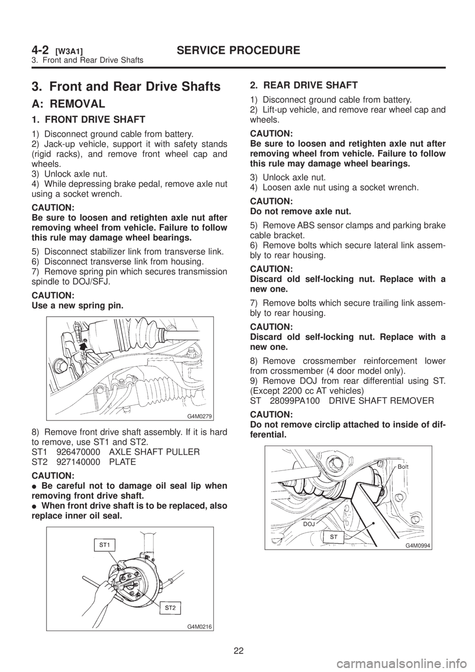
3. Front and Rear Drive Shafts
A: REMOVAL
1. FRONT DRIVE SHAFT
1) Disconnect ground cable from battery.
2) Jack-up vehicle, support it with safety stands
(rigid racks), and remove front wheel cap and
wheels.
3) Unlock axle nut.
4) While depressing brake pedal, remove axle nut
using a socket wrench.
CAUTION:
Be sure to loosen and retighten axle nut after
removing wheel from vehicle. Failure to follow
this rule may damage wheel bearings.
5) Disconnect stabilizer link from transverse link.
6) Disconnect transverse link from housing.
7) Remove spring pin which secures transmission
spindle to DOJ/SFJ.
CAUTION:
Use a new spring pin.
G4M0279
8) Remove front drive shaft assembly. If it is hard
to remove, use ST1 and ST2.
ST1 926470000 AXLE SHAFT PULLER
ST2 927140000 PLATE
CAUTION:
IBe careful not to damage oil seal lip when
removing front drive shaft.
IWhen front drive shaft is to be replaced, also
replace inner oil seal.
G4M0216
2. REAR DRIVE SHAFT
1) Disconnect ground cable from battery.
2) Lift-up vehicle, and remove rear wheel cap and
wheels.
CAUTION:
Be sure to loosen and retighten axle nut after
removing wheel from vehicle. Failure to follow
this rule may damage wheel bearings.
3) Unlock axle nut.
4) Loosen axle nut using a socket wrench.
CAUTION:
Do not remove axle nut.
5) Remove ABS sensor clamps and parking brake
cable bracket.
6) Remove bolts which secure lateral link assem-
bly to rear housing.
CAUTION:
Discard old self-locking nut. Replace with a
new one.
7) Remove bolts which secure trailing link assem-
bly to rear housing.
CAUTION:
Discard old self-locking nut. Replace with a
new one.
8) Remove crossmember reinforcement lower
from crossmember (4 door model only).
9) Remove DOJ from rear differential using ST.
(Except 2200 cc AT vehicles)
ST 28099PA100 DRIVE SHAFT REMOVER
CAUTION:
Do not remove circlip attached to inside of dif-
ferential.
G4M0994
22
4-2[W3A1]SERVICE PROCEDURE
3. Front and Rear Drive Shafts
Page 780 of 1456
E: INSTALLATION
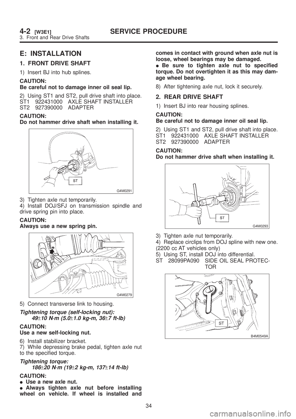
1. FRONT DRIVE SHAFT
1) Insert BJ into hub splines.
CAUTION:
Be careful not to damage inner oil seal lip.
2) Using ST1 and ST2, pull drive shaft into place.
ST1 922431000 AXLE SHAFT INSTALLER
ST2 927390000 ADAPTER
CAUTION:
Do not hammer drive shaft when installing it.
G4M0291
3) Tighten axle nut temporarily.
4) Install DOJ/SFJ on transmission spindle and
drive spring pin into place.
CAUTION:
Always use a new spring pin.
G4M0279
5) Connect transverse link to housing.
Tightening torque (self-locking nut):
49
±10 N´m (5.0±1.0 kg-m, 36±7 ft-lb)
CAUTION:
Use a new self-locking nut.
6) Install stabilizer bracket.
7) While depressing brake pedal, tighten axle nut
to the specified torque.
Tightening torque:
186
±20 N´m (19±2 kg-m, 137±14 ft-lb)
CAUTION:
IUse a new axle nut.
IAlways tighten axle nut before installing
wheel on vehicle. If wheel is installed andcomes in contact with ground when axle nut is
loose, wheel bearings may be damaged.
IBe sure to tighten axle nut to specified
torque. Do not overtighten it as this may dam-
age wheel bearing.
8) After tightening axle nut, lock it securely.
2. REAR DRIVE SHAFT
1) Insert BJ into rear housing splines.
CAUTION:
Be careful not to damage inner oil seal lip.
2) Using ST1 and ST2, pull drive shaft into place.
ST1 922431000 AXLE SHAFT INSTALLER
ST2 927390000 ADAPTER
CAUTION:
Do not hammer drive shaft when installing it.
G4M0293
3) Tighten axle nut temporarily.
4) Replace circlips from DOJ spline with new one.
(2200 cc AT vehicles only)
5) Using ST, install DOJ into differential.
ST 28099PA090 SIDE OIL SEAL PROTEC-
TOR
B4M0549A
34
4-2[W3E1]SERVICE PROCEDURE
3. Front and Rear Drive Shafts
Page 781 of 1456
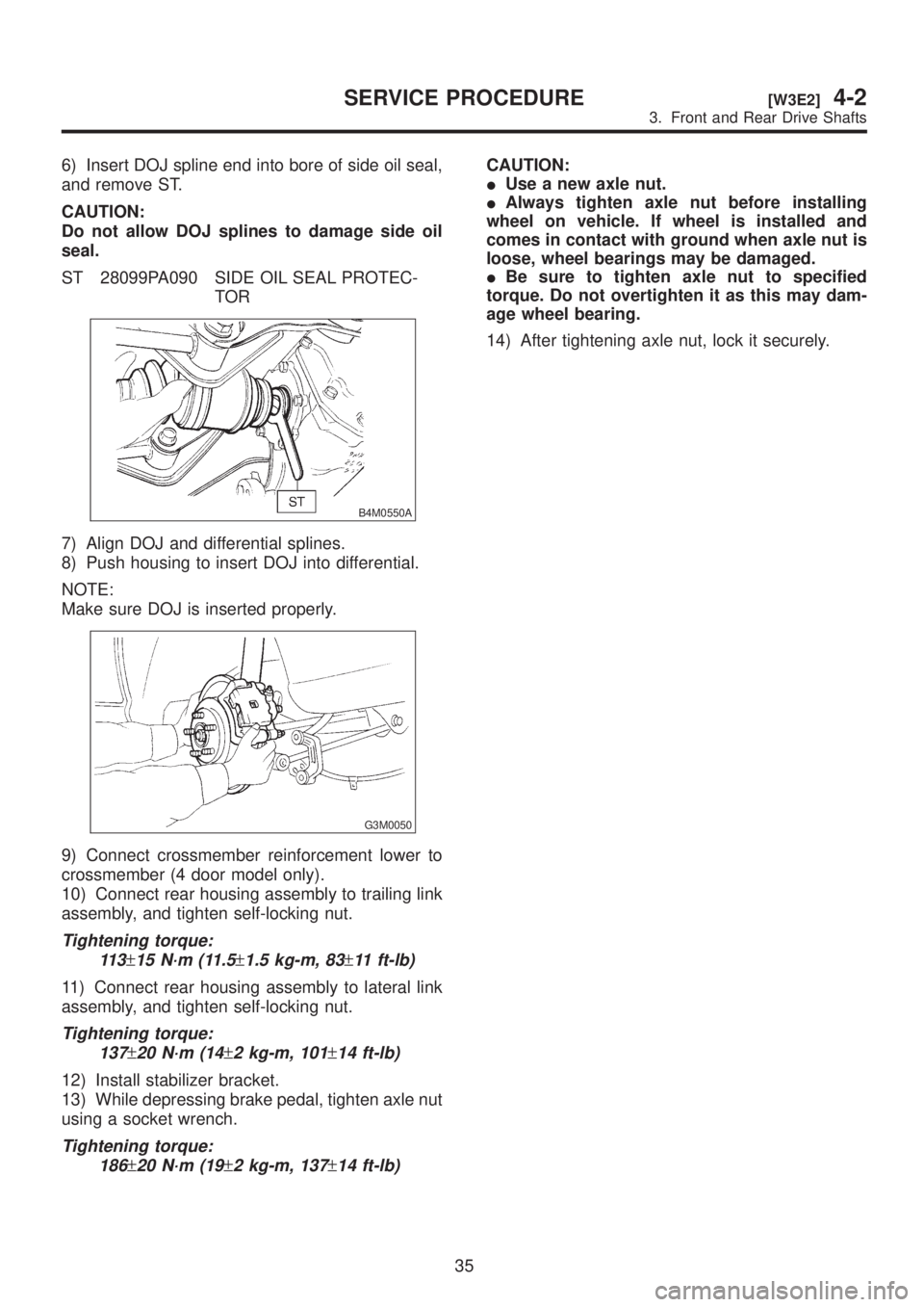
6) Insert DOJ spline end into bore of side oil seal,
and remove ST.
CAUTION:
Do not allow DOJ splines to damage side oil
seal.
ST 28099PA090 SIDE OIL SEAL PROTEC-
TOR
B4M0550A
7) Align DOJ and differential splines.
8) Push housing to insert DOJ into differential.
NOTE:
Make sure DOJ is inserted properly.
G3M0050
9) Connect crossmember reinforcement lower to
crossmember (4 door model only).
10) Connect rear housing assembly to trailing link
assembly, and tighten self-locking nut.
Tightening torque:
11 3
±15 N´m (11.5±1.5 kg-m, 83±11 ft-lb)
11) Connect rear housing assembly to lateral link
assembly, and tighten self-locking nut.
Tightening torque:
137
±20 N´m (14±2 kg-m, 101±14 ft-lb)
12) Install stabilizer bracket.
13) While depressing brake pedal, tighten axle nut
using a socket wrench.
Tightening torque:
186
±20 N´m (19±2 kg-m, 137±14 ft-lb)
CAUTION:
IUse a new axle nut.
IAlways tighten axle nut before installing
wheel on vehicle. If wheel is installed and
comes in contact with ground when axle nut is
loose, wheel bearings may be damaged.
IBe sure to tighten axle nut to specified
torque. Do not overtighten it as this may dam-
age wheel bearing.
14) After tightening axle nut, lock it securely.
35
[W3E2]4-2SERVICE PROCEDURE
3. Front and Rear Drive Shafts