wheel SUBARU LEGACY 1999 Service Manual PDF
[x] Cancel search | Manufacturer: SUBARU, Model Year: 1999, Model line: LEGACY, Model: SUBARU LEGACY 1999Pages: 1456, PDF Size: 59.93 MB
Page 727 of 1456
B: INSPECTION
1) Check bushing for cracks, fatigue or damage.
2) Check stabilizer link for deformities, cracks, or
damage, and bushing for protrusions from the hole
of stabilizer link and its play.
C: INSTALLATION
1) To install, reverse the removal procedure.
NOTE:
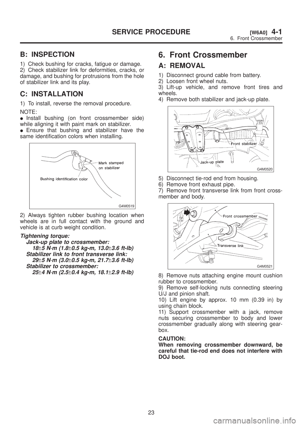
IInstall bushing (on front crossmember side)
while aligning it with paint mark on stabilizer.
IEnsure that bushing and stabilizer have the
same identification colors when installing.
G4M0519
2) Always tighten rubber bushing location when
wheels are in full contact with the ground and
vehicle is at curb weight condition.
Tightening torque:
Jack-up plate to crossmember:
18
±5 N´m (1.8±0.5 kg-m, 13.0±3.6 ft-lb)
Stabilizer link to front transverse link:
29
±5 N´m (3.0±0.5 kg-m, 21.7±3.6 ft-lb)
Stabilizer to crossmember:
25
±4 N´m (2.5±0.4 kg-m, 18.1±2.9 ft-lb)
6. Front Crossmember
A: REMOVAL
1) Disconnect ground cable from battery.
2) Loosen front wheel nuts.
3) Lift-up vehicle, and remove front tires and
wheels.
4) Remove both stabilizer and jack-up plate.
G4M0520
5) Disconnect tie-rod end from housing.
6) Remove front exhaust pipe.
7) Remove front transverse link from front cross-
member and body.
G4M0521
8) Remove nuts attaching engine mount cushion
rubber to crossmember.
9) Remove self-locking nuts connecting steering
U/J and pinion shaft.
10) Lift engine by approx. 10 mm (0.39 in) by
using chain block.
11) Support crossmember with a jack, remove
nuts securing crossmember to body and lower
crossmember gradually along with steering gear-
box.
CAUTION:
When removing crossmember downward, be
careful that tie-rod end does not interfere with
DOJ boot.
23
[W6A0]4-1SERVICE PROCEDURE
6. Front Crossmember
Page 728 of 1456
B: INSTALLATION
1) Installation is in the reverse order of removal
procedures.
CAUTION:
Always tighten rubber bushing when wheels
are in full contact with the ground and vehicle
is at curb weight condition.
Tightening torque:
Transverse link bushing to crossmember:
98
±15 N´m (10.0±1.5 kg-m, 72±11 ft-lb)
Stabilizer to bushing:
25
±4 N´m (2.5±0.4 kg-m, 18.1±2.9 ft-lb)
Tie-rod end to housing:
27.0
±2.5 N´m (2.75±0.25 kg-m, 19.9±1.8
ft-lb)
Front cushion rubber to crossmember:
69
±15 N´m (7.0±1.5 kg-m, 51±11 ft-lb)
Universal joint to pinion shaft:
24
±3 N´m (2.4±0.3 kg-m, 17.4±2.2 ft-lb)
Crossmember to body:
98
±15 N´m (10.0±1.5 kg-m, 72±11 ft-lb)
2) Purge air from power steering system.
NOTE:
Check wheel alignment and adjust if necessary.
24
4-1[W6B0]SERVICE PROCEDURE
6. Front Crossmember
Page 729 of 1456

7. Rear Trailing Link
A: REMOVAL
H4M1066C
(1) Trailing link
(2) Front bushing
(3) Rear bushing
(4) Bracket(5) Housing
(6) Self-locking nutTightening torque: N´m (kg-m, ft-lb)
T1:
98±20 (10.0±2.0, 72±14)
T2:11 3±15 (11.5±1.5, 83±11 )
1) Loosen rear wheel nuts.
2) Lift-up vehicle, support it with safety stands
(rigid racks) and remove rear wheels.
3) Remove both rear parking brake clamp and
ABS sensor harness. (ABS equipped models.)
4) Remove bolt which secure trailing link to trailing
link bracket.
B4M0570A
5) Remove bolt which secure trailing link to rear
housing.
25
[W7A0]4-1SERVICE PROCEDURE
7. Rear Trailing Link
Page 732 of 1456
E: INSTALLATION
Installation is in the reverse order of removal.
CAUTION:
Always tighten rubber bushing location when
wheels are in full contact with the ground and
vehicle is at curb weight condition.
NOTE:
Check wheel alignment and adjust if necessary.
28
4-1[W7E0]SERVICE PROCEDURE
7. Rear Trailing Link
Page 733 of 1456

8. Lateral Link
A: REMOVAL
H4M1067C
(1) Crossmember
(2) Adjusting bolt
(3) Stabilizer link
(4) Rear lateral link
(5) Bushing (C)
(6) Bushing (A)
(7) Front lateral link(8) Bushing (B)
(9) Washer
(10) Cap (Protection)
(11) Trailing link
(12) Self-locking nutTightening torque: N´m (kg-m, ft-lb)
T1:
44±6 (4.5±0.6, 32.5±4.3)
T2:98±15 (10.0±1.5, 72±11 )
T3:11 3±15 (11.5±1.5, 83±11
T4:137±20 (14.0±2.0, 101±14)
1) Loosen wheel nuts. Lift-up vehicle and remove
wheel.
2) Remove stabilizers link from lateral link.
3) Remove ABS sensor harness from trailing link.
(ABS equipped models.)
4) Remove bolt securing trailing link to housing.
B4M0573A
5) Remove bolts which secure lateral link assem-
bly to rear housing.
6) Remove crossmember reinforcement lower
from crossmember. (4 door model only)
29
[W8A0]4-1SERVICE PROCEDURE
8. Lateral Link
Page 736 of 1456
![SUBARU LEGACY 1999 Service Manual PDF E: INSTALLATION
To install, reverse removal procedures, reading the
following instructions.
IInstallation of DOJ to differential <Ref. to 4-2
[W3E2].>
CAUTION:
IDo not allow DOJ splines to damage side](/img/17/57435/w960_57435-735.png "SUBARU LEGACY 1999 Service Manual PDF E: INSTALLATION
To install, reverse removal procedures, reading the
following instructions.
IInstallation of DOJ to differential <Ref. to 4-2
[W3E2].>
CAUTION:
IDo not allow DOJ splines to damage side")
E: INSTALLATION
To install, reverse removal procedures, reading the
following instructions.
IInstallation of DOJ to differential
CAUTION:
IDo not allow DOJ splines to damage side oil
seal.
IAlways tighten rubber bushing when wheels
are in full contact with the ground and vehicle
is at curb weight condition.
ITighten nut when installing adjusting bolt.
IReplace self-locking nut with new one.
NOTE:
ILateral link washers identification color is gold
color.
ICheck wheel alignment and adjust if necessary.
32
4-1[W8E0]SERVICE PROCEDURE
8. Lateral Link
Page 737 of 1456
9. Rear Strut
A: REMOVAL
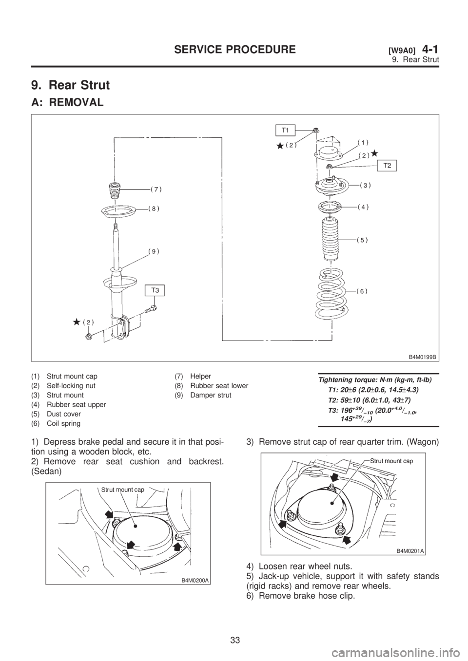
B4M0199B
(1) Strut mount cap
(2) Self-locking nut
(3) Strut mount
(4) Rubber seat upper
(5) Dust cover
(6) Coil spring(7) Helper
(8) Rubber seat lower
(9) Damper strutTightening torque: N´m (kg-m, ft-lb)
T1:
20±6 (2.0±0.6, 14.5±4.3)
T2:59±10 (6.0±1.0, 43±7)
T3:196+39/þ10(20.0+4.0/þ1.0,
145+29/þ7)
1) Depress brake pedal and secure it in that posi-
tion using a wooden block, etc.
2) Remove rear seat cushion and backrest.
(Sedan)
B4M0200A
3) Remove strut cap of rear quarter trim. (Wagon)
B4M0201A
4) Loosen rear wheel nuts.
5) Jack-up vehicle, support it with safety stands
(rigid racks) and remove rear wheels.
6) Remove brake hose clip.
33
[W9A0]4-1SERVICE PROCEDURE
9. Rear Strut
Page 739 of 1456
CAUTION:
ICheck that hose clip is positioned properly.
ICheck brake hose for twisting, or excessive
tension.
IModels equipped with ABS:
Do not subject ABS sensor harness to exces-
sive tension.
6) Be sure to bleed air from brake system.
7) Lower vehicle and tighten wheel nut.
Tightening torque:
88
±10 N´m (9±1 kg-m, 65±7 ft-lb)
8) Sedan:
Install rear seat backrest and rear seat cushion.
Wagon:
Install strut cap of rear quarter trim.
NOTE:
Check wheel alignment and adjust if necessary.
35
[W9E0]4-1SERVICE PROCEDURE
9. Rear Strut
Page 741 of 1456
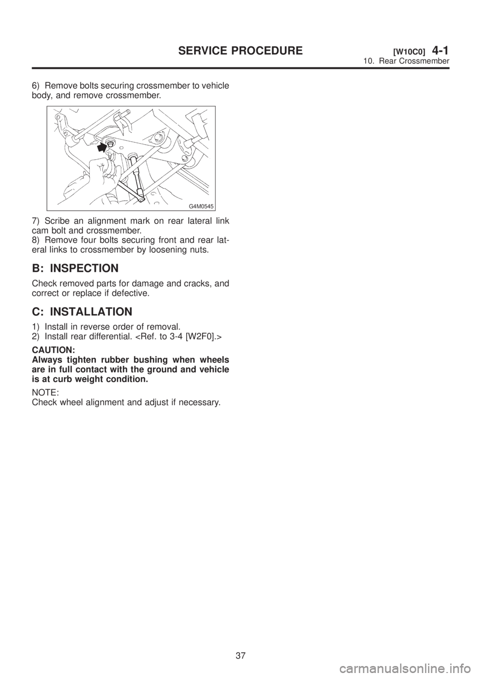
6) Remove bolts securing crossmember to vehicle
body, and remove crossmember.
G4M0545
7) Scribe an alignment mark on rear lateral link
cam bolt and crossmember.
8) Remove four bolts securing front and rear lat-
eral links to crossmember by loosening nuts.
B: INSPECTION
Check removed parts for damage and cracks, and
correct or replace if defective.
C: INSTALLATION
1) Install in reverse order of removal.
2) Install rear differential.
CAUTION:
Always tighten rubber bushing when wheels
are in full contact with the ground and vehicle
is at curb weight condition.
NOTE:
Check wheel alignment and adjust if necessary.
37
[W10C0]4-1SERVICE PROCEDURE
10. Rear Crossmember
Page 743 of 1456
C: INSTALLATION
1) To install, reverse the removal procedure.
NOTE:
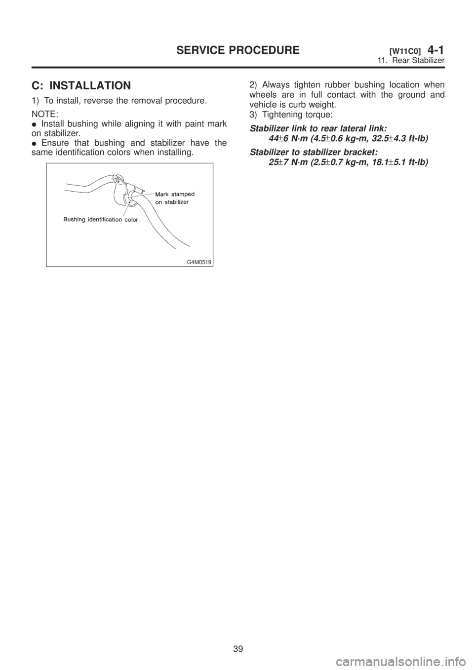
IInstall bushing while aligning it with paint mark
on stabilizer.
IEnsure that bushing and stabilizer have the
same identification colors when installing.
G4M0519
2) Always tighten rubber bushing location when
wheels are in full contact with the ground and
vehicle is curb weight.
3) Tightening torque:
Stabilizer link to rear lateral link:
44
±6 N´m (4.5±0.6 kg-m, 32.5±4.3 ft-lb)
Stabilizer to stabilizer bracket:
25
±7 N´m (2.5±0.7 kg-m, 18.1±5.1 ft-lb)
39
[W11C0]4-1SERVICE PROCEDURE
11. Rear Stabilizer