SUBARU LEGACY 1999 Service Repair Manual
Manufacturer: SUBARU, Model Year: 1999, Model line: LEGACY, Model: SUBARU LEGACY 1999Pages: 1456, PDF Size: 59.93 MB
Page 841 of 1456
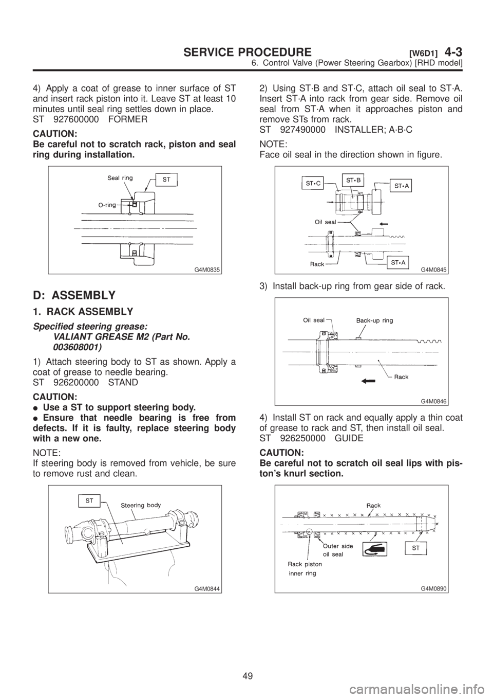
4) Apply a coat of grease to inner surface of ST
and insert rack piston into it. Leave ST at least 10
minutes until seal ring settles down in place.
ST 927600000 FORMER
CAUTION:
Be careful not to scratch rack, piston and seal
ring during installation.
G4M0835
D: ASSEMBLY
1. RACK ASSEMBLY
Specified steering grease:
VALIANT GREASE M2 (Part No.
003608001)
1) Attach steering body to ST as shown. Apply a
coat of grease to needle bearing.
ST 926200000 STAND
CAUTION:
IUse a ST to support steering body.
IEnsure that needle bearing is free from
defects. If it is faulty, replace steering body
with a new one.
NOTE:
If steering body is removed from vehicle, be sure
to remove rust and clean.
G4M0844
2) Using ST´B and ST´C, attach oil seal to ST´A.
Insert ST´A into rack from gear side. Remove oil
seal from ST´A when it approaches piston and
remove STs from rack.
ST 927490000 INSTALLER; A´B´C
NOTE:
Face oil seal in the direction shown in figure.
G4M0845
3) Install back-up ring from gear side of rack.
G4M0846
4) Install ST on rack and equally apply a thin coat
of grease to rack and ST, then install oil seal.
ST 926250000 GUIDE
CAUTION:
Be careful not to scratch oil seal lips with pis-
ton's knurl section.
G4M0890
49
[W6D1]4-3SERVICE PROCEDURE
6. Control Valve (Power Steering Gearbox) [RHD model]
Page 842 of 1456
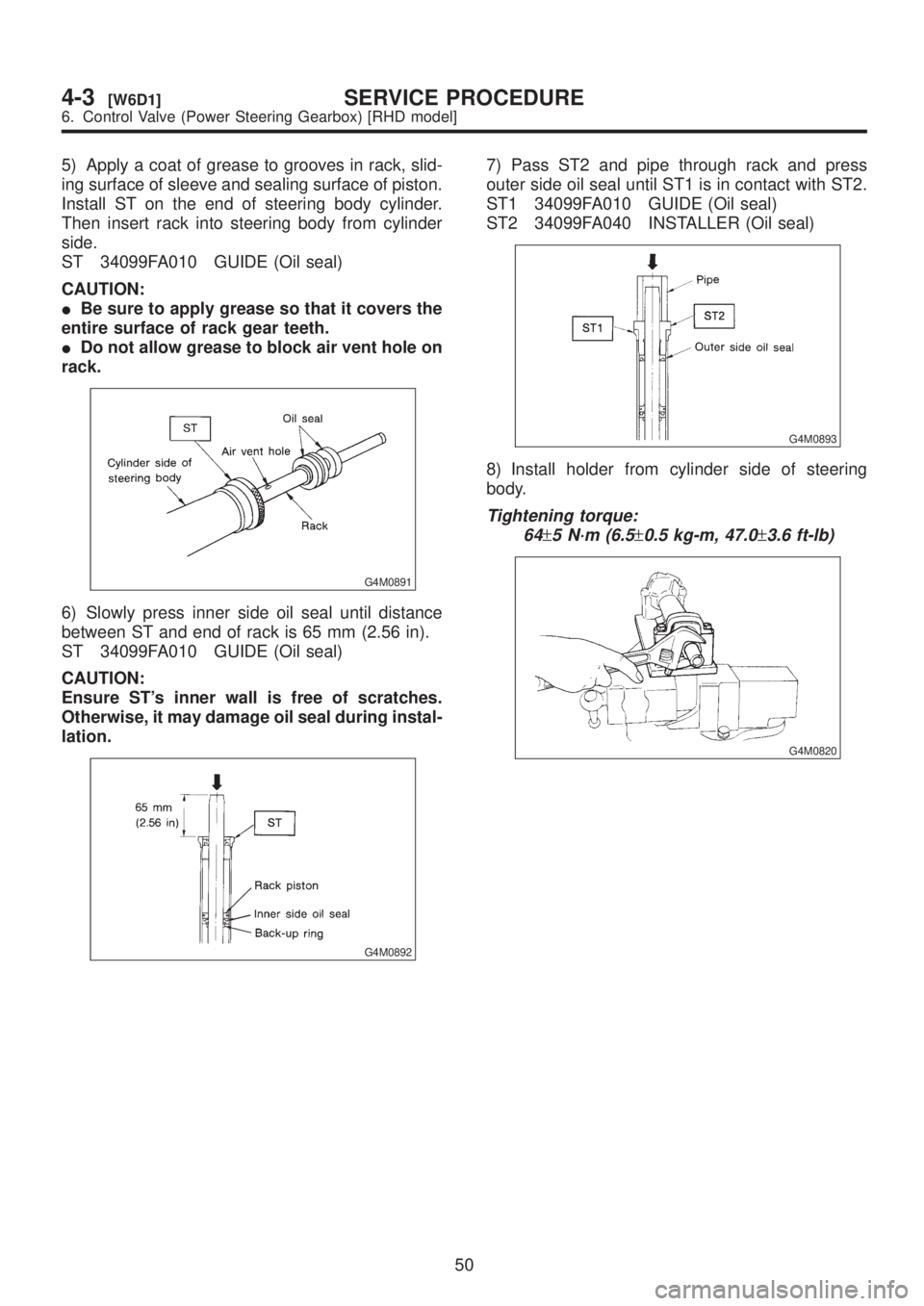
5) Apply a coat of grease to grooves in rack, slid-
ing surface of sleeve and sealing surface of piston.
Install ST on the end of steering body cylinder.
Then insert rack into steering body from cylinder
side.
ST 34099FA010 GUIDE (Oil seal)
CAUTION:
IBe sure to apply grease so that it covers the
entire surface of rack gear teeth.
IDo not allow grease to block air vent hole on
rack.
G4M0891
6) Slowly press inner side oil seal until distance
between ST and end of rack is 65 mm (2.56 in).
ST 34099FA010 GUIDE (Oil seal)
CAUTION:
Ensure ST's inner wall is free of scratches.
Otherwise, it may damage oil seal during instal-
lation.
G4M0892
7) Pass ST2 and pipe through rack and press
outer side oil seal until ST1 is in contact with ST2.
ST1 34099FA010 GUIDE (Oil seal)
ST2 34099FA040 INSTALLER (Oil seal)
G4M0893
8) Install holder from cylinder side of steering
body.
Tightening torque:
64
±5 N´m (6.5±0.5 kg-m, 47.0±3.6 ft-lb)
G4M0820
50
4-3[W6D1]SERVICE PROCEDURE
6. Control Valve (Power Steering Gearbox) [RHD model]
Page 843 of 1456
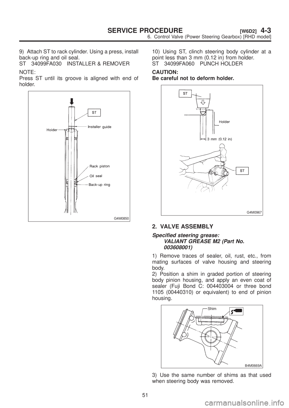
9) Attach ST to rack cylinder. Using a press, install
back-up ring and oil seal.
ST 34099FA030 INSTALLER & REMOVER
NOTE:
Press ST until its groove is aligned with end of
holder.
G4M0850
10) Using ST, clinch steering body cylinder at a
point less than 3 mm (0.12 in) from holder.
ST 34099FA060 PUNCH HOLDER
CAUTION:
Be careful not to deform holder.
G4M0967
2. VALVE ASSEMBLY
Specified steering grease:
VALIANT GREASE M2 (Part No.
003608001)
1) Remove traces of sealer, oil, rust, etc., from
mating surfaces of valve housing and steering
body.
2) Position a shim in graded portion of steering
body pinion housing, and apply an even coat of
sealer (Fuji Bond C: 004403004 or three bond
1105 (00440310) or equivalent) to end of pinion
housing.
B4M0669A
3) Use the same number of shims as that used
when steering body was removed.
51
[W6D2]4-3SERVICE PROCEDURE
6. Control Valve (Power Steering Gearbox) [RHD model]
Page 844 of 1456
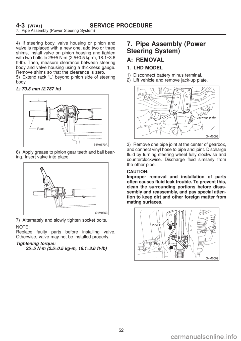
4) If steering body, valve housing or pinion and
valve is replaced with a new one, add two or three
shims, install valve on pinion housing and tighten
with two bolts to 25±5 N´m (2.5±0.5 kg-m, 18.1±3.6
ft-lb). Then, measure clearance between steering
body and valve housing using a thickness gauge.
Remove shims so that the clearance is zero.
5) Extend rack ªLº beyond pinion side of steering
body.
L: 70.8 mm (2.787 in)
B4M0670A
6) Apply grease to pinion gear teeth and ball bear-
ing. Insert valve into place.
G4M0853
7) Alternately and slowly tighten socket bolts.
NOTE:
Replace faulty parts before installing valve.
Otherwise, valve may not be installed properly.
Tightening torque:
25
±5 N´m (2.5±0.5 kg-m, 18.1±3.6 ft-lb)
7. Pipe Assembly (Power
Steering System)
A: REMOVAL
1. LHD MODEL
1) Disconnect battery minus terminal.
2) Lift vehicle and remove jack-up plate.
G4M0098
3) Remove one pipe joint at the center of gearbox,
and connect vinyl hose to pipe and joint. Discharge
fluid by turning steering wheel fully clockwise and
counterclockwise. Discharge fluid similarly from
the other pipe.
CAUTION:
Improper removal and installation of parts
often causes fluid leak trouble. To prevent this,
clean the surrounding portions before disas-
sembly and reassembly, and pay special atten-
tion to keep dirt and other foreign matter from
mating surfaces.
G4M0099
52
4-3[W7A1]SERVICE PROCEDURE
7. Pipe Assembly (Power Steering System)
Page 845 of 1456
4) If steering body, valve housing or pinion and
valve is replaced with a new one, add two or three
shims, install valve on pinion housing and tighten
with two bolts to 25±5 N´m (2.5±0.5 kg-m, 18.1±3.6
ft-lb). Then, measure clearance between steering
body and valve housing using a thickness gauge.
Remove shims so that the clearance is zero.
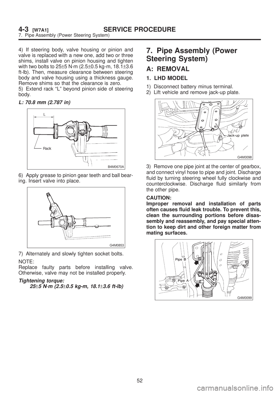
5) Extend rack ªLº beyond pinion side of steering
body.
L: 70.8 mm (2.787 in)
B4M0670A
6) Apply grease to pinion gear teeth and ball bear-
ing. Insert valve into place.
G4M0853
7) Alternately and slowly tighten socket bolts.
NOTE:
Replace faulty parts before installing valve.
Otherwise, valve may not be installed properly.
Tightening torque:
25
±5 N´m (2.5±0.5 kg-m, 18.1±3.6 ft-lb)
7. Pipe Assembly (Power
Steering System)
A: REMOVAL
1. LHD MODEL
1) Disconnect battery minus terminal.
2) Lift vehicle and remove jack-up plate.
G4M0098
3) Remove one pipe joint at the center of gearbox,
and connect vinyl hose to pipe and joint. Discharge
fluid by turning steering wheel fully clockwise and
counterclockwise. Discharge fluid similarly from
the other pipe.
CAUTION:
Improper removal and installation of parts
often causes fluid leak trouble. To prevent this,
clean the surrounding portions before disas-
sembly and reassembly, and pay special atten-
tion to keep dirt and other foreign matter from
mating surfaces.
G4M0099
52
4-3[W7A1]SERVICE PROCEDURE
7. Pipe Assembly (Power Steering System)
Page 846 of 1456
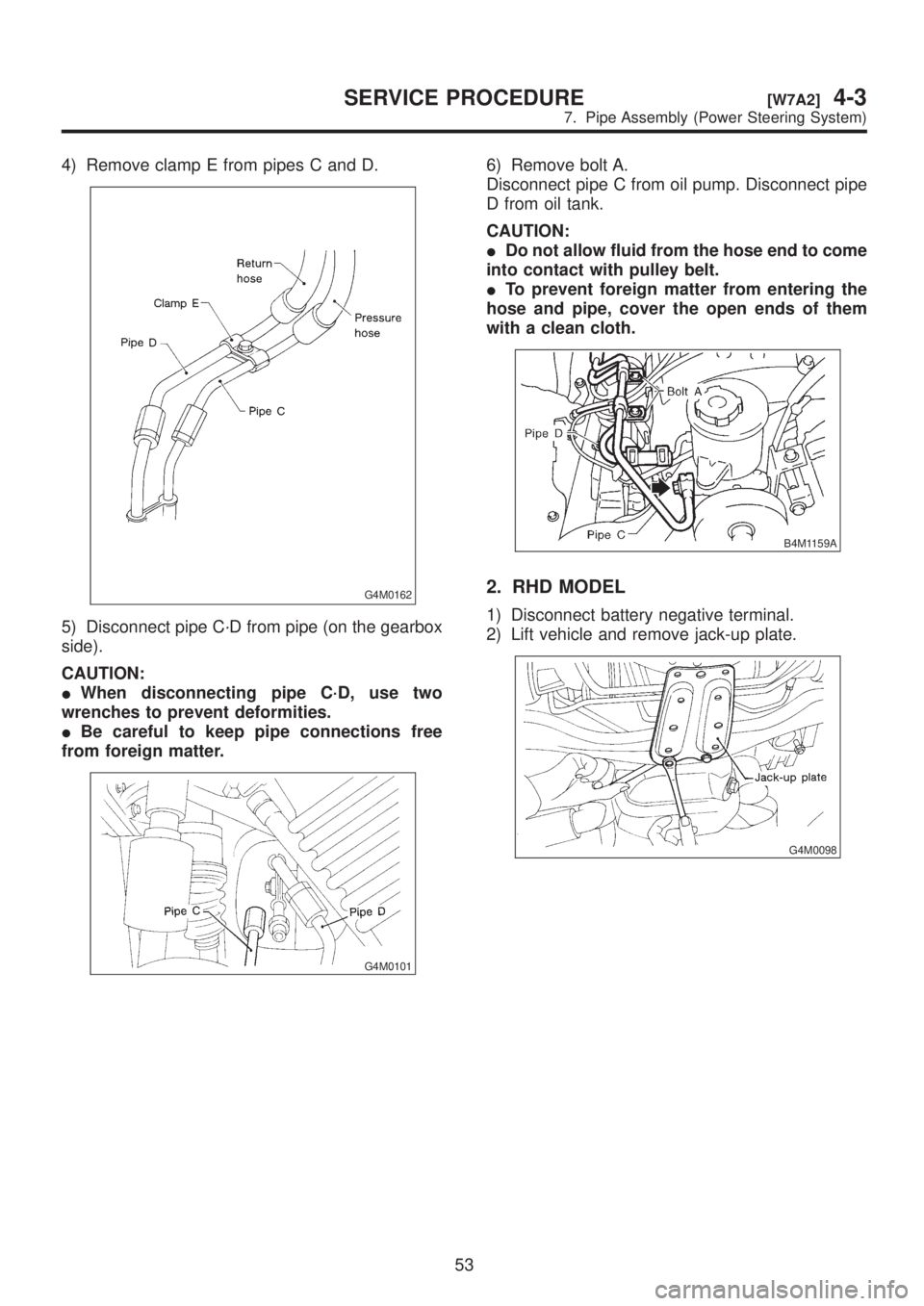
4) Remove clamp E from pipes C and D.
G4M0162
5) Disconnect pipe C´D from pipe (on the gearbox
side).
CAUTION:
IWhen disconnecting pipe C´D, use two
wrenches to prevent deformities.
IBe careful to keep pipe connections free
from foreign matter.
G4M0101
6) Remove bolt A.
Disconnect pipe C from oil pump. Disconnect pipe
D from oil tank.
CAUTION:
IDo not allow fluid from the hose end to come
into contact with pulley belt.
ITo prevent foreign matter from entering the
hose and pipe, cover the open ends of them
with a clean cloth.
B4M1159A
2. RHD MODEL
1) Disconnect battery negative terminal.
2) Lift vehicle and remove jack-up plate.
G4M0098
53
[W7A2]4-3SERVICE PROCEDURE
7. Pipe Assembly (Power Steering System)
Page 847 of 1456
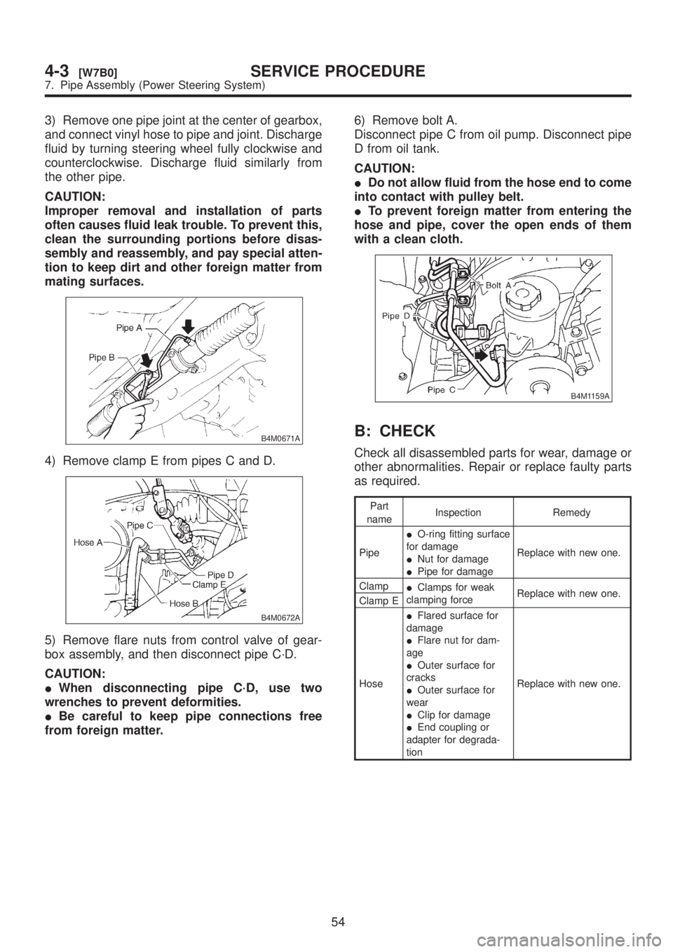
3) Remove one pipe joint at the center of gearbox,
and connect vinyl hose to pipe and joint. Discharge
fluid by turning steering wheel fully clockwise and
counterclockwise. Discharge fluid similarly from
the other pipe.
CAUTION:
Improper removal and installation of parts
often causes fluid leak trouble. To prevent this,
clean the surrounding portions before disas-
sembly and reassembly, and pay special atten-
tion to keep dirt and other foreign matter from
mating surfaces.
B4M0671A
4) Remove clamp E from pipes C and D.
B4M0672A
5) Remove flare nuts from control valve of gear-
box assembly, and then disconnect pipe C´D.
CAUTION:
IWhen disconnecting pipe C´D, use two
wrenches to prevent deformities.
IBe careful to keep pipe connections free
from foreign matter.6) Remove bolt A.
Disconnect pipe C from oil pump. Disconnect pipe
D from oil tank.
CAUTION:
IDo not allow fluid from the hose end to come
into contact with pulley belt.
ITo prevent foreign matter from entering the
hose and pipe, cover the open ends of them
with a clean cloth.
B4M1159A
B: CHECK
Check all disassembled parts for wear, damage or
other abnormalities. Repair or replace faulty parts
as required.
Part
nameInspection Remedy
PipeIO-ring fitting surface
for damage
INut for damage
IPipe for damageReplace with new one.
Clamp
IClamps for weak
clamping forceReplace with new one.
Clamp E
HoseIFlared surface for
damage
IFlare nut for dam-
age
IOuter surface for
cracks
IOuter surface for
wear
IClip for damage
IEnd coupling or
adapter for degrada-
tionReplace with new one.
54
4-3[W7B0]SERVICE PROCEDURE
7. Pipe Assembly (Power Steering System)
Page 848 of 1456
C: INSTALLATION
1. LHD MODEL
1) Interconnect pipes C and D.
Tightening torque:
Joint nut
15
±5 N´m (1.5±0.5 kg-m, 10.8±3.6 ft-lb)
CAUTION:
Visually check that hose between tank and pipe
D is free from bending or twisting.
B4M1159A
2) Connect pipe D from oil tank.
3) Connect pipe C from oil pump.
CAUTION:
Use a new gasket.
Tightening torque:
34
±5 N´m (3.5±0.5 kg-m, 25.3±3.6 ft-lb)
4) Tighten bolt A.
Tightening torque:
13
±3 N´m (1.3±0.3 kg-m, 9.4±2.2 ft-lb)
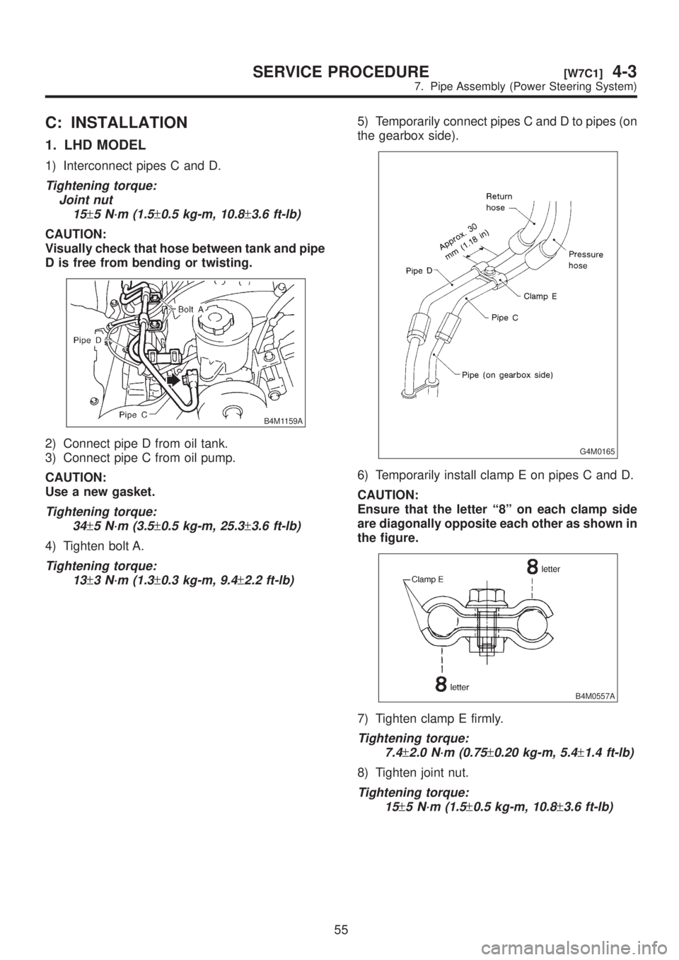
5) Temporarily connect pipes C and D to pipes (on
the gearbox side).
G4M0165
6) Temporarily install clamp E on pipes C and D.
CAUTION:
Ensure that the letter ª8º on each clamp side
are diagonally opposite each other as shown in
the figure.
B4M0557A
7) Tighten clamp E firmly.
Tightening torque:
7.4
±2.0 N´m (0.75±0.20 kg-m, 5.4±1.4 ft-lb)
8) Tighten joint nut.
Tightening torque:
15
±5 N´m (1.5±0.5 kg-m, 10.8±3.6 ft-lb)
55
[W7C1]4-3SERVICE PROCEDURE
7. Pipe Assembly (Power Steering System)
Page 849 of 1456
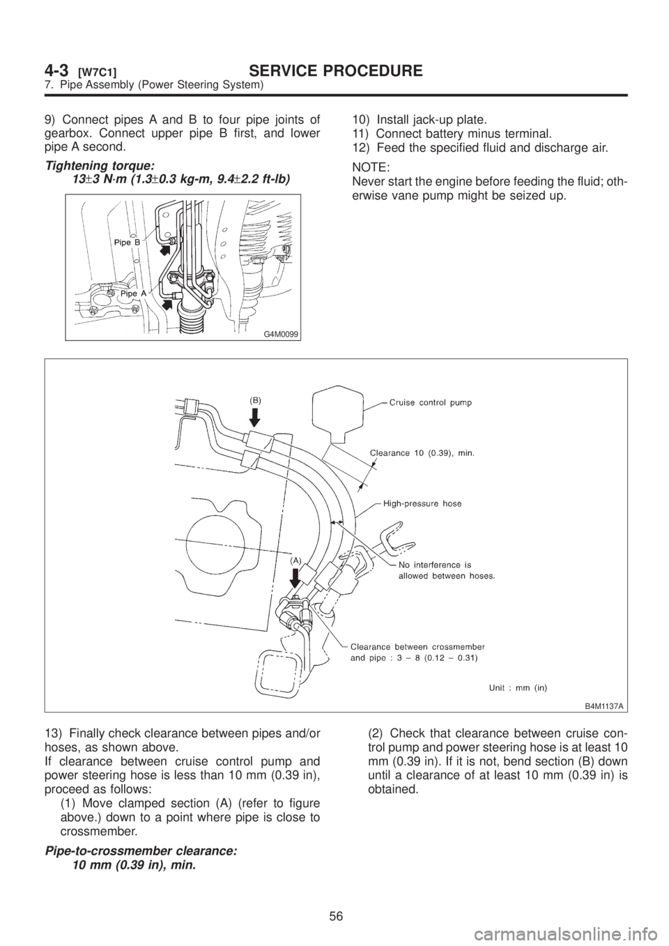
9) Connect pipes A and B to four pipe joints of
gearbox. Connect upper pipe B first, and lower
pipe A second.
Tightening torque:
13
±3 N´m (1.3±0.3 kg-m, 9.4±2.2 ft-lb)
G4M0099
10) Install jack-up plate.
11) Connect battery minus terminal.
12) Feed the specified fluid and discharge air.
NOTE:
Never start the engine before feeding the fluid; oth-
erwise vane pump might be seized up.
B4M1137A
13) Finally check clearance between pipes and/or
hoses, as shown above.
If clearance between cruise control pump and
power steering hose is less than 10 mm (0.39 in),
proceed as follows:
(1) Move clamped section (A) (refer to figure
above.) down to a point where pipe is close to
crossmember.
Pipe-to-crossmember clearance:
10 mm (0.39 in), min.
(2) Check that clearance between cruise con-
trol pump and power steering hose is at least 10
mm (0.39 in). If it is not, bend section (B) down
until a clearance of at least 10 mm (0.39 in) is
obtained.
56
4-3[W7C1]SERVICE PROCEDURE
7. Pipe Assembly (Power Steering System)
Page 850 of 1456
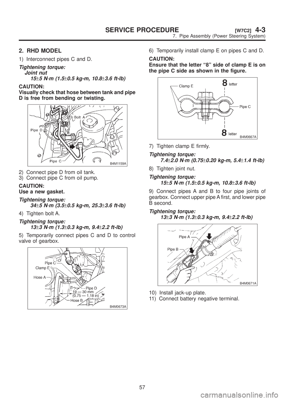
2. RHD MODEL
1) Interconnect pipes C and D.
Tightening torque:
Joint nut
15
±5 N´m (1.5±0.5 kg-m, 10.8±3.6 ft-lb)
CAUTION:
Visually check that hose between tank and pipe
D is free from bending or twisting.
B4M1159A
2) Connect pipe D from oil tank.
3) Connect pipe C from oil pump.
CAUTION:
Use a new gasket.
Tightening torque:
34
±5 N´m (3.5±0.5 kg-m, 25.3±3.6 ft-lb)
4) Tighten bolt A.
Tightening torque:
13
±3 N´m (1.3±0.3 kg-m, 9.4±2.2 ft-lb)
5) Temporarily connect pipes C and D to control
valve of gearbox.
B4M0673A
6) Temporarily install clamp E on pipes C and D.
CAUTION:
Ensure that the letter ª8º side of clamp E is on
the pipe C side as shown in the figure.
B4M0667A
7) Tighten clamp E firmly.
Tightening torque:
7.4
±2.0 N´m (0.75±0.20 kg-m, 5.4±1.4 ft-lb)
8) Tighten joint nut.
Tightening torque:
15
±5 N´m (1.5±0.5 kg-m, 10.8±3.6 ft-lb)
9) Connect pipes A and B to four pipe joints of
gearbox. Connect upper pipe A first, and lower pipe
B second.
Tightening torque:
13
±3 N´m (1.3±0.3 kg-m, 9.4±2.2 ft-lb)
B4M0671A
10) Install jack-up plate.
11) Connect battery negative terminal.
57
[W7C2]4-3SERVICE PROCEDURE
7. Pipe Assembly (Power Steering System)