SUBARU TRIBECA 2009 1.G Service Workshop Manual
Manufacturer: SUBARU, Model Year: 2009, Model line: TRIBECA, Model: SUBARU TRIBECA 2009 1.GPages: 2453, PDF Size: 46.32 MB
Page 1861 of 2453
LU(H6DO)-12
Oil Pan and Strainer
LUBRICATION
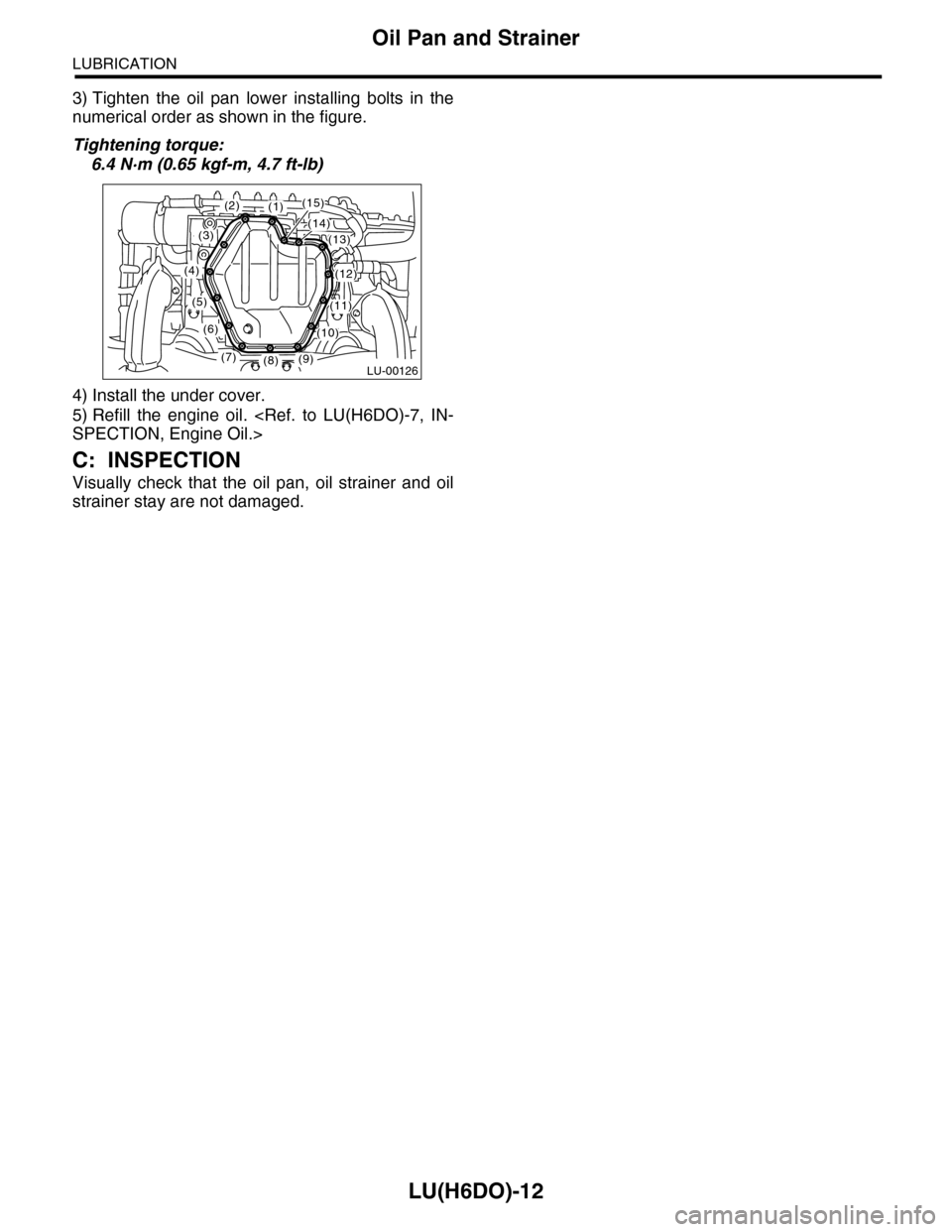
3) Tighten the oil pan lower installing bolts in the
numerical order as shown in the figure.
Tightening torque:
6.4 N·m (0.65 kgf-m, 4.7 ft-lb)
4) Install the under cover.
5) Refill the engine oil.
C: INSPECTION
Visually check that the oil pan, oil strainer and oil
strainer stay are not damaged.
(1)(2)
(3)
(4)
(5)
(6)
(7)(8)(9)
(10)
(11)
(12)
(13)
(14)
(15)
LU-00126
Page 1862 of 2453
LU(H6DO)-13
Oil Pressure Switch
LUBRICATION
7. Oil Pressure Switch
A: REMOVAL
1) Set the vehicle on a lift.
2) Disconnect the ground cable from battery.
3) Lift-up the vehicle.
4) Remove the under cover.
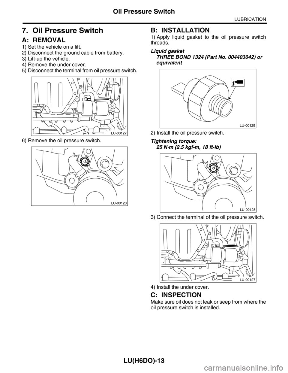
5) Disconnect the terminal from oil pressure switch.
6) Remove the oil pressure switch.
B: INSTALLATION
1) Apply liquid gasket to the oil pressure switch
threads.
Liquid gasket
THREE BOND 1324 (Part No. 004403042) or
equivalent
2) Install the oil pressure switch.
Tightening torque:
25 N·m (2.5 kgf-m, 18 ft-lb)
3) Connect the terminal of the oil pressure switch.
4) Install the under cover.
C: INSPECTION
Make sure oil does not leak or seep from where the
oil pressure switch is installed.
LU-00127
LU-00128
LU-00129
LU-00128
LU-00127
Page 1863 of 2453
LU(H6DO)-14
Engine Oil Filter
LUBRICATION
8. Engine Oil Filter
A: REMOVAL
1) Lift-up the vehicle.
2) Drain the engine oil.
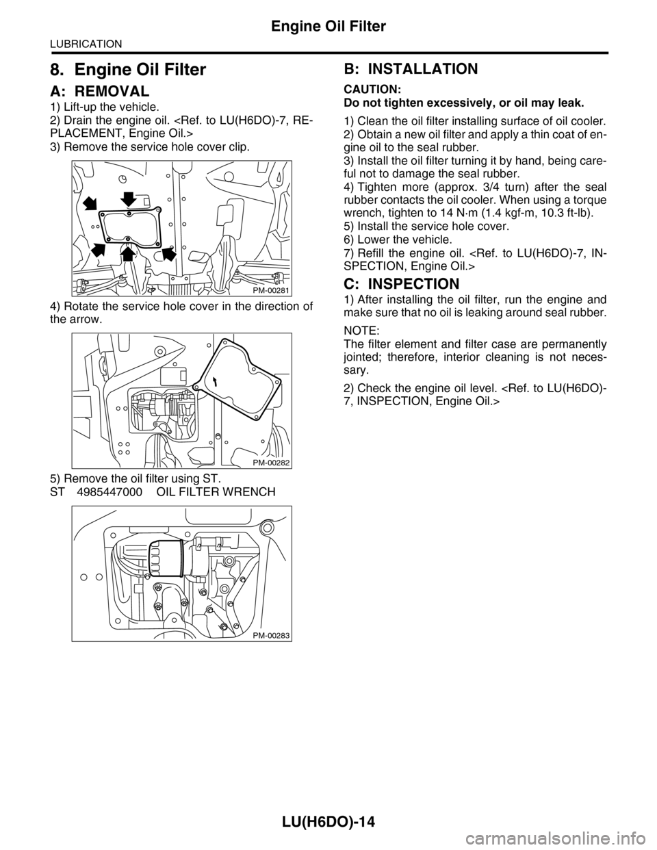
3) Remove the service hole cover clip.
4) Rotate the service hole cover in the direction of
the arrow.
5) Remove the oil filter using ST.
ST 4985447000 OIL FILTER WRENCH
B: INSTALLATION
CAUTION:
Do not tighten excessively, or oil may leak.
1) Clean the oil filter installing surface of oil cooler.
2) Obtain a new oil filter and apply a thin coat of en-
gine oil to the seal rubber.
3) Install the oil filter turning it by hand, being care-
ful not to damage the seal rubber.
4) Tighten more (approx. 3/4 turn) after the seal
rubber contacts the oil cooler. When using a torque
wrench, tighten to 14 N·m (1.4 kgf-m, 10.3 ft-lb).
5) Install the service hole cover.
6) Lower the vehicle.
7) Refill the engine oil.
C: INSPECTION
1) After installing the oil filter, run the engine and
make sure that no oil is leaking around seal rubber.
NOTE:
The filter element and filter case are permanently
jointed; therefore, interior cleaning is not neces-
sary.
2) Check the engine oil level.
PM-00281
PM-00282
PM-00283
Page 1864 of 2453
LU(H6DO)-15
Oil Cooler
LUBRICATION
9. Oil Cooler
A: REMOVAL
1) Lift-up the vehicle.
2) Remove the under cover.
3) Drain engine coolant.
4) Drain the engine oil.
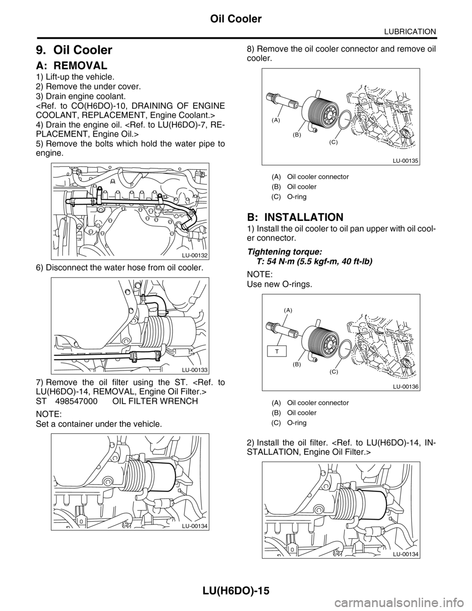
5) Remove the bolts which hold the water pipe to
engine.
6) Disconnect the water hose from oil cooler.
7) Remove the oil filter using the ST.
ST 498547000 OIL FILTER WRENCH
NOTE:
Set a container under the vehicle.
8) Remove the oil cooler connector and remove oil
cooler.
B: INSTALLATION
1) Install the oil cooler to oil pan upper with oil cool-
er connector.
Tightening torque:
T: 54 N·m (5.5 kgf-m, 40 ft-lb)
NOTE:
Use new O-rings.
2) Install the oil filter.
LU-00132
LU-00133
LU-00134
(A) Oil cooler connector
(B) Oil cooler
(C) O-ring
(A) Oil cooler connector
(B) Oil cooler
(C) O-ring
(A)
(B)(C)
LU-00135
(A)
(B)(C)
T
LU-00136
LU-00134
Page 1865 of 2453
LU(H6DO)-16
Oil Cooler
LUBRICATION
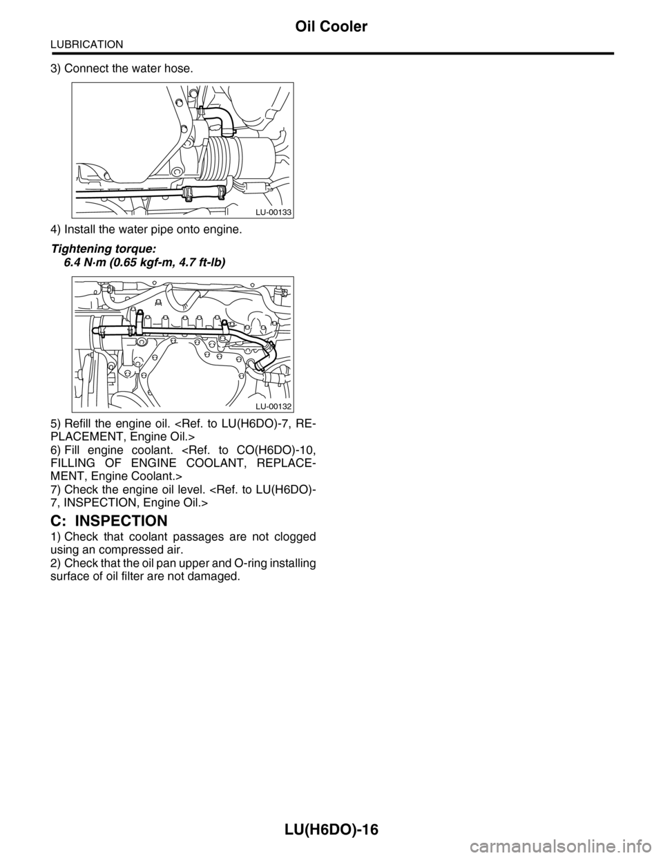
3) Connect the water hose.
4) Install the water pipe onto engine.
Tightening torque:
6.4 N·m (0.65 kgf-m, 4.7 ft-lb)
5) Refill the engine oil.
6) Fill engine coolant.
MENT, Engine Coolant.>
7) Check the engine oil level.
C: INSPECTION
1) Check that coolant passages are not clogged
using an compressed air.
2) Check that the oil pan upper and O-ring installing
surface of oil filter are not damaged.
LU-00133
LU-00132
Page 1866 of 2453
LU(H6DO)-17
General Diagnostics Table
LUBRICATION
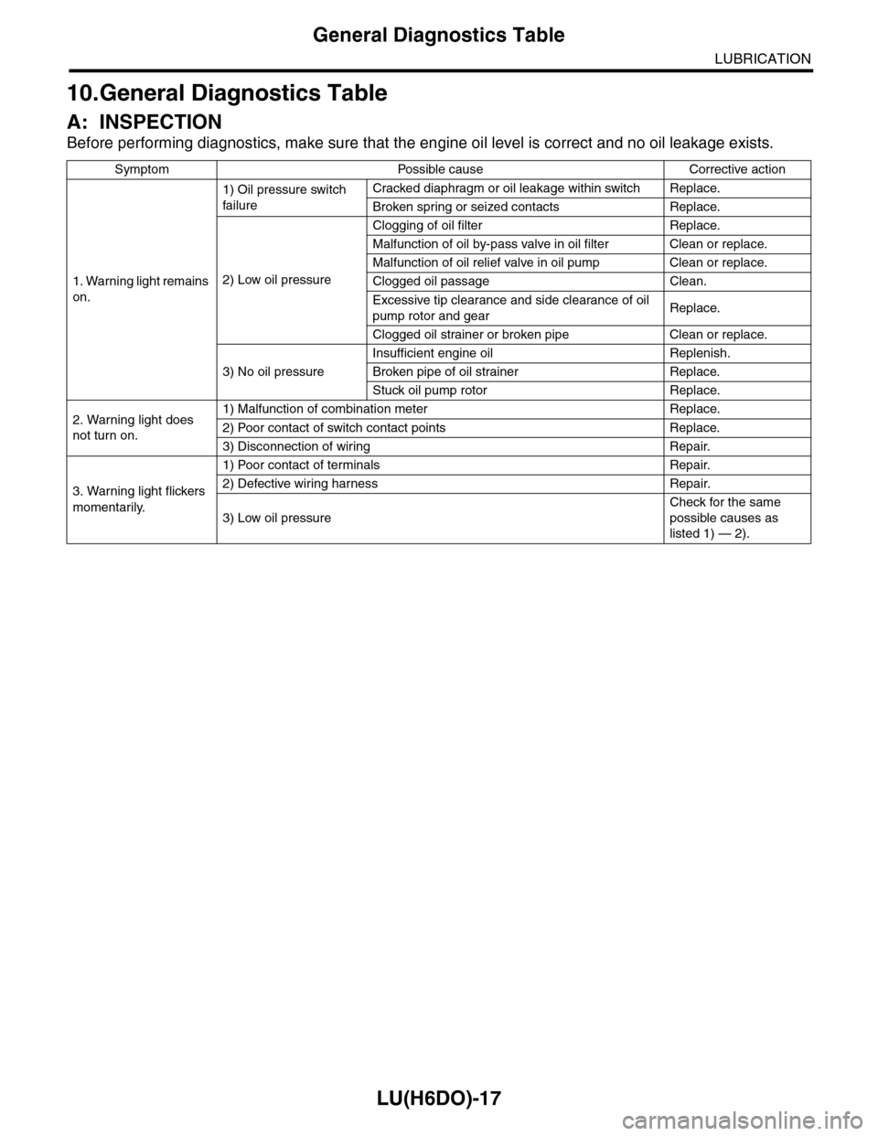
10.General Diagnostics Table
A: INSPECTION
Before performing diagnostics, make sure that the engine oil level is correct and no oil leakage exists.
Symptom Possible cause Corrective action
1. Warning light remains
on.
1) Oil pressure switch
failure
Cracked diaphragm or oil leakage within switch Replace.
Broken spring or seized contacts Replace.
2) Low oil pressure
Clogging of oil filter Replace.
Malfunction of oil by-pass valve in oil filter Clean or replace.
Malfunction of oil relief valve in oil pump Clean or replace.
Clogged oil passage Clean.
Excessive tip clearance and side clearance of oil
pump rotor and gearReplace.
Clogged oil strainer or broken pipe Clean or replace.
3) No oil pressure
Insufficient engine oil Replenish.
Broken pipe of oil strainer Replace.
Stuck oil pump rotor Replace.
2. Warning light does
not turn on.
1) Malfunction of combination meter Replace.
2) Poor contact of switch contact points Replace.
3) Disconnection of wiring Repair.
3. Warning light flickers
momentarily.
1) Poor contact of terminals Repair.
2) Defective wiring harness Repair.
3) Low oil pressure
Check for the same
possible causes as
listed 1) — 2).
Page 1867 of 2453
LU(H6DO)-18
General Diagnostics Table
LUBRICATION
Page 1868 of 2453
ME(H6DO)-2
General Description
MECHANICAL
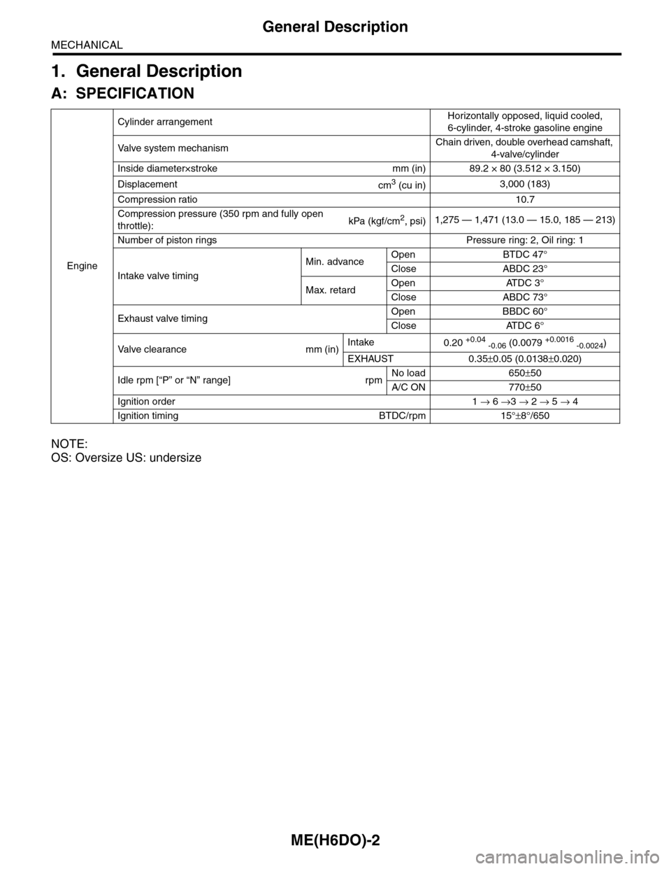
1. General Description
A: SPECIFICATION
NOTE:
OS: Oversize US: undersize
Engine
Cylinder arrangementHorizontally opposed, liquid cooled,
6-cylinder, 4-stroke gasoline engine
Va l ve s y s t e m m e c h a n i s mChain driven, double overhead camshaft,
4-valve/cylinder
Inside diameter×stroke mm (in) 89.2 × 80 (3.512 × 3.150)
Displacementcm3 (cu in)3,000 (183)
Compression ratio10.7
Compression pressure (350 rpm and fully open
throttle):kPa (kgf/cm2, psi)1,275 — 1,471 (13.0 — 15.0, 185 — 213)
Number of piston rings Pressure ring: 2, Oil ring: 1
Intake valve timing
Min. advanceOpen BTDC 47°
Close ABDC 23°
Max. retardOpen ATDC 3°
Close ABDC 73°
Exhaust valve timingOpen BBDC 60°
Close ATDC 6°
Va l ve c l e a r a n c e m m ( i n )Intake0.20 +0.04 -0.06 (0.0079 +0.0016 -0.0024)
EXHAUST 0.35±0.05 (0.0138±0.020)
Idle rpm [“P” or “N” range] rpmNo load 650±50
A/C ON 770±50
Ignition order 1 → 6 →3 → 2 → 5 → 4
Ignition timing BTDC/rpm 15°±8°/650
Page 1869 of 2453
ME(H6DO)-3
General Description
MECHANICAL
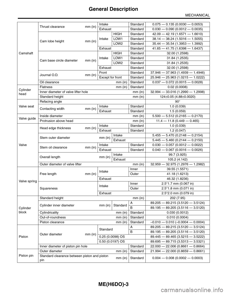
Camshaft
Thrust clearance mm (in)Intake Standard 0.075 — 0.135 (0.0030 — 0.0053)
Exhaust Standard 0.030 — 0.090 (0.0012 — 0.0035)
Cam lobe height mm (in)Intake
HIGH Standard 42.09 — 42.19 (1.6571 — 1.6610)
LOW1 Standard 38.14 — 38.24 (1.5016 — 1.5055)
LOW2 Standard 35.44 — 35.54 (1.3953 — 1.3992)
Exhaust Standard 41.65 — 41.75 (1.6398 — 1.6437)
Cam base circle diameter mm (in)Intake
HIGH Standard 32.00 (1.2598)
LOW1 Standard 31.84 (1.2535)
LOW2 Standard 31.84 (1.2535)
Exhaust Standard 32.00 (1.2598)
Journal O.D. mm (in)Fr o nt S ta n da r d 3 7. 9 46 — 3 7 . 96 3 ( 1 . 49 3 9 — 1. 4 9 46 )
Except for front Standard 25.946 — 25.963 (1.0215 — 1.0222)
Oil clearance mm (in) Standard 0.037 — 0.072 (0.0015 — 0.0028)
Cylinder
head
Flatness mm (in) Standard 0.02 (0.0008)
Inner diameter of valve lifter hole mm (in) 32.994 — 33.016 (1.2990 — 1.2998)
Standard height mm (in) 124±0.05 (4.88±0.0020)
Va l ve s e a t
Refacing angle90°
Contacting width mm (in)Intake Standard 1.0 (0.039)
Exhaust Standard 1.5 (0.059)
Va l ve g u i d eInside diameter mm (in) 5.500 — 5.512 (0.2165 — 0.2170)
Protrusion above head mm (in) 11.4 — 11.8 (0.449 — 0.465)
Va l ve
Head edge thickness mm (in)Intake Standard 1.0 (0.039)
Exhaust Standard 1.2 (0.047)
Stem outer diameter mm (in)Intake 5.455 — 5.470 (0.2148 — 0.2154)
Exhaust 5.445 — 5.460 (0.2144 — 0.2150)
Stem oil clearance mm (in)Intake Standard 0.030 — 0.057 (0.0012 — 0.0022)
Exhaust Standard 0.040 — 0.067 (0.0016 — 0.0026)
Overall length mm (in)Intake 99.7 (3.925)
Exhaust 105.2 (4.142)
Outer diameter of valve lifter mm (in) 32.959 — 32.975 (1.2976 — 1.2982)
Va l ve s p r i n g
Free length mm (in)IntakeInner 39.55 (1.5571)
Outer 41.18 (1.6213)
Exhaust 46.32 (1.8236)
SquarenessIntakeInner 2.5°1.7 mm (0.067 in)
Outer 2.5°1.8 mm (0.071 in)
Exhaust 2.5°2.0 mm (0.079 in)
Cylinder
block
Standard height mm (in) 202 (7.95)
Cylinder inner diameter mm (in) StandardA89.205 — 89.215 (3.5120 — 3.5124)
B89.195 — 89.205 (3.5116 — 3.5120)
Cylindricality mm (in) Standard 0.030 (0.0012)
Out-of-roundness mm (in) Standard 0.010 (0.0004)
Piston clearance mm (in) Standard –0.010 — 0.010 (–0.0004 — 0.0004)
PistonOuter diameter mm (in)
StandardA89.205 — 89.215 (3.5120 — 3.5124)
B89.195 — 89.205 (3.5116 — 3.5120)
0.25 (0.0098) OS 89.445 — 89.465 (3.5215 — 3.5222)
0.50 (0.0197) OS 89.695 — 89.715 (3.5313 — 3.5321)
Inner diameter of piston pin hole Standard 22.000 — 22.006 (0.8661 — 0.8664)
Piston pin
Outer diameter mm (in) Standard 21.994 — 22.000 (0.8659 — 0.8661)
Standard clearance between piston and piston
pinmm (in) Standard 0.004 — 0.008 (0.0002 — 0.0003)
Page 1870 of 2453
ME(H6DO)-4
General Description
MECHANICAL
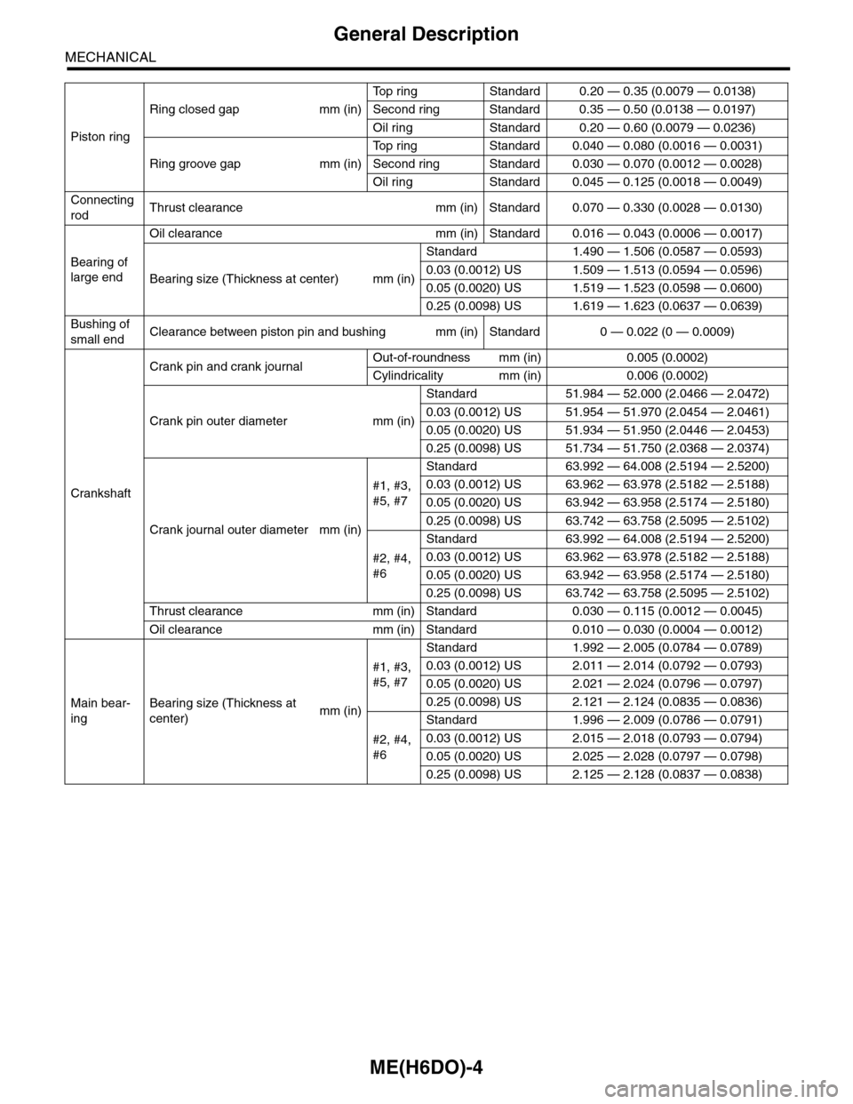
Piston ring
Ring closed gap mm (in)
To p r i n g S t a n d a r d 0 . 2 0 — 0 . 3 5 ( 0 . 0 0 7 9 — 0 . 0 1 3 8 )
Second ring Standard 0.35 — 0.50 (0.0138 — 0.0197)
Oil ring Standard 0.20 — 0.60 (0.0079 — 0.0236)
Ring groove gap mm (in)
To p r i n g S t a n d a r d 0 . 0 4 0 — 0 . 0 8 0 ( 0 . 0 0 1 6 — 0 . 0 0 3 1 )
Second ring Standard 0.030 — 0.070 (0.0012 — 0.0028)
Oil ring Standard 0.045 — 0.125 (0.0018 — 0.0049)
Connecting
rodThrust clearance mm (in) Standard 0.070 — 0.330 (0.0028 — 0.0130)
Bearing of
large end
Oil clearance mm (in) Standard 0.016 — 0.043 (0.0006 — 0.0017)
Bearing size (Thickness at center) mm (in)
Standard 1.490 — 1.506 (0.0587 — 0.0593)
0.03 (0.0012) US 1.509 — 1.513 (0.0594 — 0.0596)
0.05 (0.0020) US 1.519 — 1.523 (0.0598 — 0.0600)
0.25 (0.0098) US 1.619 — 1.623 (0.0637 — 0.0639)
Bushing of
small endClearance between piston pin and bushing mm (in) Standard 0 — 0.022 (0 — 0.0009)
Crankshaft
Crank pin and crank journalOut-of-roundness mm (in) 0.005 (0.0002)
Cylindricality mm (in) 0.006 (0.0002)
Crank pin outer diameter mm (in)
Standard 51.984 — 52.000 (2.0466 — 2.0472)
0.03 (0.0012) US 51.954 — 51.970 (2.0454 — 2.0461)
0.05 (0.0020) US 51.934 — 51.950 (2.0446 — 2.0453)
0.25 (0.0098) US 51.734 — 51.750 (2.0368 — 2.0374)
Crank journal outer diameter mm (in)
#1, #3,
#5, #7
Standard 63.992 — 64.008 (2.5194 — 2.5200)
0.03 (0.0012) US 63.962 — 63.978 (2.5182 — 2.5188)
0.05 (0.0020) US 63.942 — 63.958 (2.5174 — 2.5180)
0.25 (0.0098) US 63.742 — 63.758 (2.5095 — 2.5102)
#2, #4,
#6
Standard 63.992 — 64.008 (2.5194 — 2.5200)
0.03 (0.0012) US 63.962 — 63.978 (2.5182 — 2.5188)
0.05 (0.0020) US 63.942 — 63.958 (2.5174 — 2.5180)
0.25 (0.0098) US 63.742 — 63.758 (2.5095 — 2.5102)
Thrust clearance mm (in) Standard 0.030 — 0.115 (0.0012 — 0.0045)
Oil clearance mm (in) Standard 0.010 — 0.030 (0.0004 — 0.0012)
Main bear-
ing
Bearing size (Thickness at
center)mm (in)
#1, #3,
#5, #7
Standard 1.992 — 2.005 (0.0784 — 0.0789)
0.03 (0.0012) US 2.011 — 2.014 (0.0792 — 0.0793)
0.05 (0.0020) US 2.021 — 2.024 (0.0796 — 0.0797)
0.25 (0.0098) US 2.121 — 2.124 (0.0835 — 0.0836)
#2, #4,
#6
Standard 1.996 — 2.009 (0.0786 — 0.0791)
0.03 (0.0012) US 2.015 — 2.018 (0.0793 — 0.0794)
0.05 (0.0020) US 2.025 — 2.028 (0.0797 — 0.0798)
0.25 (0.0098) US 2.125 — 2.128 (0.0837 — 0.0838)