SUBARU TRIBECA 2009 1.G Service Workshop Manual
Manufacturer: SUBARU, Model Year: 2009, Model line: TRIBECA, Model: SUBARU TRIBECA 2009 1.GPages: 2453, PDF Size: 46.32 MB
Page 1871 of 2453
ME(H6DO)-5
General Description
MECHANICAL
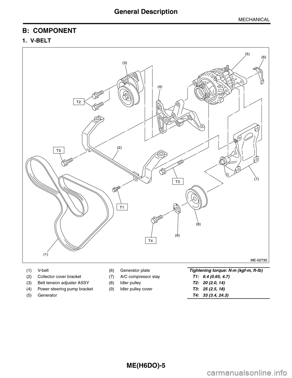
B: COMPONENT
1. V-BELT
(1) V-belt (6) Generator plateTightening torque: N·m (kgf-m, ft-lb)
(2) Collector cover bracket (7) A/C compressor stayT1: 6.4 (0.65, 4.7)
(3) Belt tension adjuster ASSY (8) Idler pulleyT2: 20 (2.0, 14)
(4) Power steering pump bracket (9) Idler pulley coverT3: 25 (2.5, 18)
(5) GeneratorT4: 33 (3.4, 24.3)
Page 1872 of 2453
ME(H6DO)-6
General Description
MECHANICAL
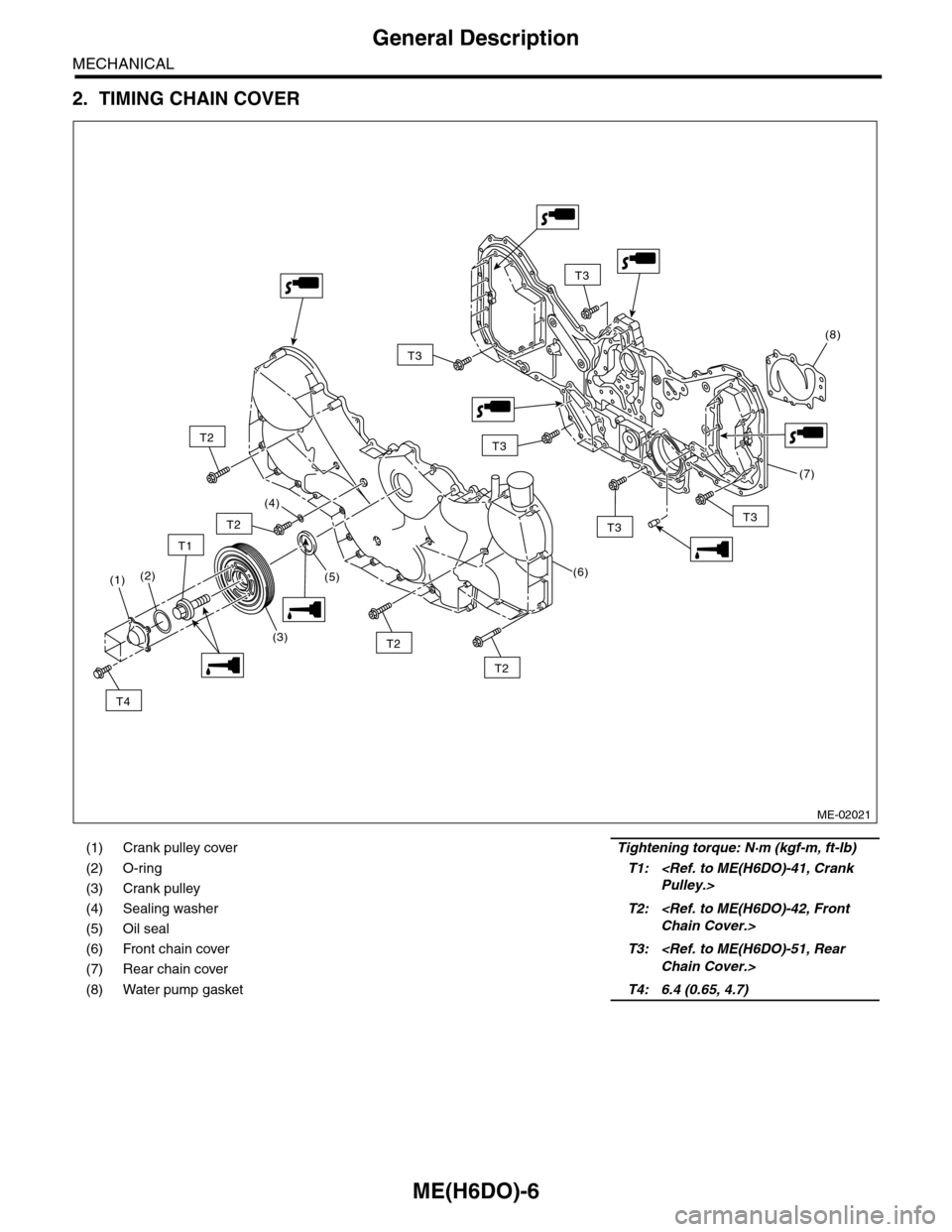
2. TIMING CHAIN COVER
(1) Crank pulley coverTightening torque: N·m (kgf-m, ft-lb)
(2) O-ringT1:
(4) Sealing washerT2:
(6) Front chain cover T3:
(8) Water pump gasket T4: 6.4 (0.65, 4.7)
ME-02021
T2
T2
T2
T2
T3T3
T3
T3
T3
(4)
(6)
(7)
(8)
(5)
T1
T4
(1)
(3)
(2)
Page 1873 of 2453
ME(H6DO)-7
General Description
MECHANICAL
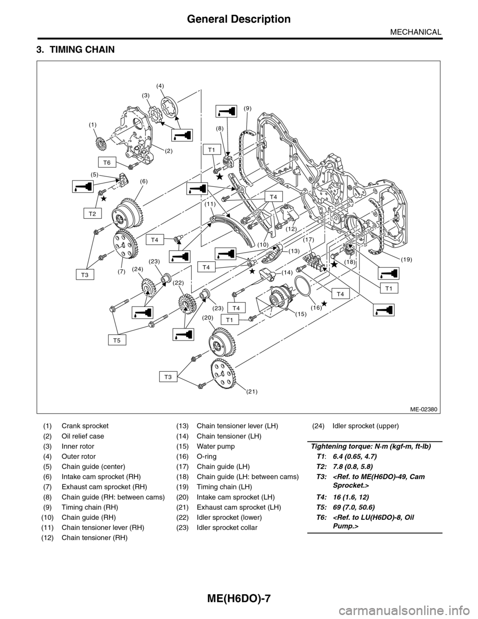
3. TIMING CHAIN
(1) Crank sprocket (13) Chain tensioner lever (LH) (24) Idler sprocket (upper)
(2) Oil relief case (14) Chain tensioner (LH)
(3) Inner rotor (15) Water pumpTightening torque: N·m (kgf-m, ft-lb)
(4) Outer rotor (16) O-ringT1:6.4 (0.65, 4.7)
(5) Chain guide (center) (17) Chain guide (LH)T2: 7.8 (0.8, 5.8)
(6) Intake cam sprocket (RH) (18) Chain guide (LH: between cams)T3:
(8) Chain guide (RH: between cams) (20) Intake cam sprocket (LH)T4: 16 (1.6, 12)
(9) Timing chain (RH) (21) Exhaust cam sprocket (LH)T5: 69 (7.0, 50.6)
(10) Chain guide (RH) (22) Idler sprocket (lower)T6:
(12) Chain tensioner (RH)
ME-02380
T6
(2)
(8)
(9)
(10)
(11)
(12)
(13)
(14)
(15)(16)
(17)
(18)(19)
(5)
T3
T3
T5
T2
T1
T1
T1
T4
T4
T4
T4
T4
(7)
(21)
(20)
(22)
(23)
(23)
(24)
(6)
(1)
(3)
(4)
Page 1874 of 2453
ME(H6DO)-8
General Description
MECHANICAL
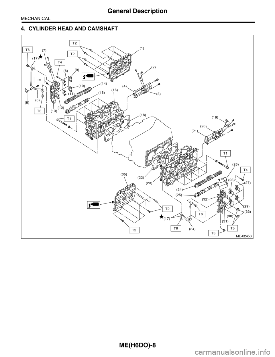
4. CYLINDER HEAD AND CAMSHAFT
ME-02453
(1)
(2)
(3)
(4)
(9)
(10)
(22)
(23)
(24)
(26)
(27)(28)
(25)
(32)
(8)
(18)
(16)
(13)(12)
(6)(5)
(14)
(15)
(19)
(20)
(21)
(7)
(11)
(31)
(34)
(35)
(30)
(29)
(33)
T3
T1
T4
T2
T2
T1
T4
T5
T2
T2T3
T6
T6
T6
T6
(17)
(17)
Page 1875 of 2453
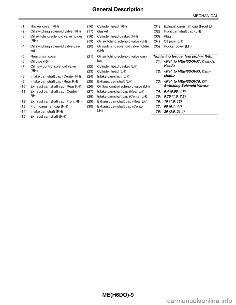
ME(H6DO)-9
General Description
MECHANICAL
(1) Rocker cover (RH) (16) Cylinder head (RH) (31) Exhaust camshaft cap (Front LH)
(2) Oil switching solenoid valve (RH) (17) Gasket (32) Front camshaft cap (LH)
(3) Oil switching solenoid valve holder
(RH)
(18) Cylinder head gasket (RH) (33) Plug
(19) Oil switching solenoid valve (LH) (34) Oil pipe (LH)
(4) Oil switching solenoid valve gas-
ket
(20) Oil switching solenoid valve holder
(LH)
(35) Rocker cover (LH)
(5) Rear chain cover (21) Oil switching solenoid valve gas-
ket
Tightening torque: N·m (kgf-m, ft-lb)
(6) Oil pipe (RH)T1:
(RH)
(22) Cylinder head gasket (LH)
(23) Cylinder head (LH)T2:
(9) Intake camshaft cap (Rear RH) (25) Exhaust camshaft (LH)T3:
(11) Exhaust camshaft cap (Center
RH)
(27) Intake camshaft cap (Rear LH)T4:6.4 (0.65, 4.7)
(28) Intake camshaft cap (Center LH)T5: 9.75 (1.0, 7.2)
(12) Exhaust camshaft cap (Front RH) (29) Exhaust camshaft cap (Rear LH)T6:16 (1.6, 12)
(13) Front camshaft cap (RH) (30) Exhaust camshaft cap (Center
LH)
T7: 60 (6.1, 44)
(14) Intake camshaft (RH)T8: 29 (3.0, 21.4)
(15) Exhaust camshaft (RH)
Page 1876 of 2453
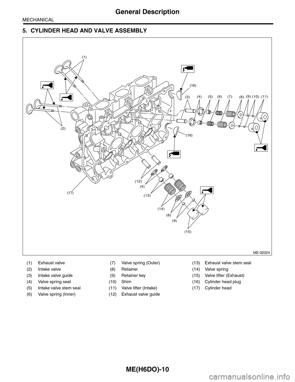
ME(H6DO)-10
General Description
MECHANICAL
5. CYLINDER HEAD AND VALVE ASSEMBLY
(1) Exhaust valve (7) Valve spring (Outer) (13) Exhaust valve stem seal
(2) Intake valve (8) Retainer (14) Valve spring
(3) Intake valve guide (9) Retainer key (15) Valve lifter (Exhaust)
(4) Valve spring seat (10) Shim (16) Cylinder head plug
(5) Intake valve stem seal (11) Valve lifter (Intake) (17) Cylinder head
(6) Valve spring (Inner) (12) Exhaust valve guide
ME-02024
(16)
(16)
(17)
(3)
(12)
(13)
(4)
(14)
(8)
(9)
(15)
(4) (5) (6)(7)(8)(9)(11)(10)
(1)
(2)
Page 1877 of 2453
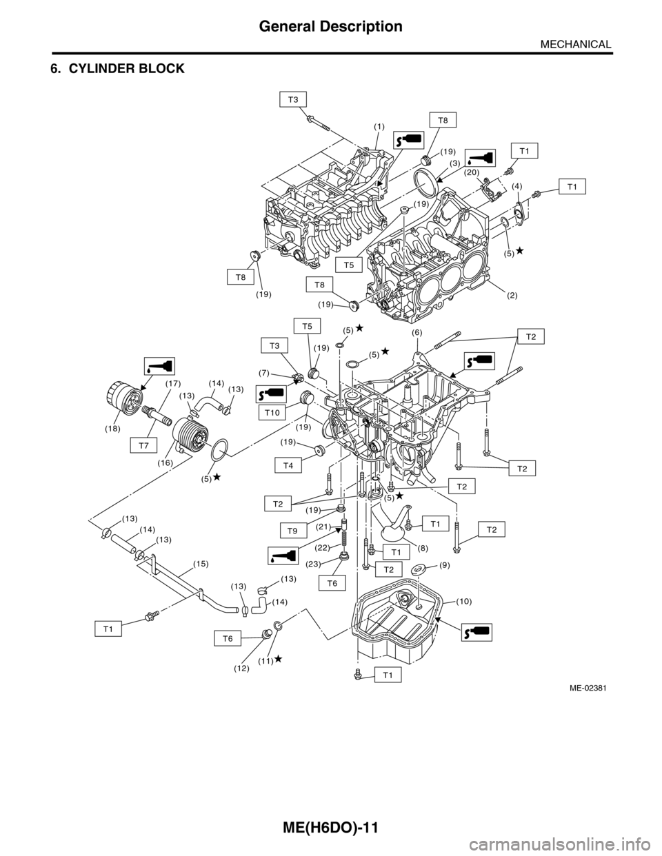
ME(H6DO)-11
General Description
MECHANICAL
6. CYLINDER BLOCK
(5)
(6)
(7)
(9)
(5)
(8)
(19)
(19)
(10)
(19)
(19)
(21)
(22)
(23)
T1
T2
T2
T2
T1
T2
T2T5
T2
T9
ME-02381
T4
T6
T10
(5)
(1)
(3)
(4)
(5)
(2)
(19)
(19)
(20)
(19)(19)
T1
T1
T8
T3
T5
T8T8
(5)
(18)
(17)
(13)
(14)(13)
(16)
(13)
(14)(13)
(15)
(13)(13)
(11)(12)
(14)
T6T1
T7
T3
T1
Page 1878 of 2453
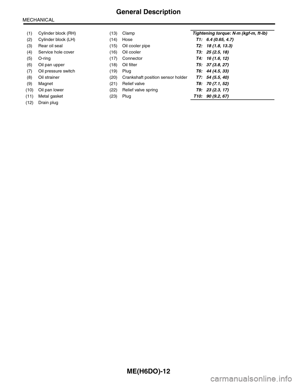
ME(H6DO)-12
General Description
MECHANICAL
(1) Cylinder block (RH) (13) ClampTightening torque: N·m (kgf-m, ft-lb)
(2) Cylinder block (LH) (14) HoseT1: 6.4 (0.65, 4.7)
(3) Rear oil seal (15) Oil cooler pipeT2: 18 (1.8, 13.3)
(4) Service hole cover (16) Oil coolerT3: 25 (2.5, 18)
(5) O-ring (17) ConnectorT4: 16 (1.6, 12)
(6) Oil pan upper (18) Oil filterT5: 37 (3.8, 27)
(7) Oil pressure switch (19) PlugT6: 44 (4.5, 33)
(8) Oil strainer (20) Crankshaft position sensor holderT7: 54 (5.5, 40)
(9) Magnet (21) Relief valveT8: 70 (7.1, 52)
(10) Oil pan lower (22) Relief valve springT9: 23 (2.3, 17)
(11) Metal gasket (23) PlugT10: 90 (9.2, 67)
(12) Drain plug
Page 1879 of 2453
ME(H6DO)-13
General Description
MECHANICAL
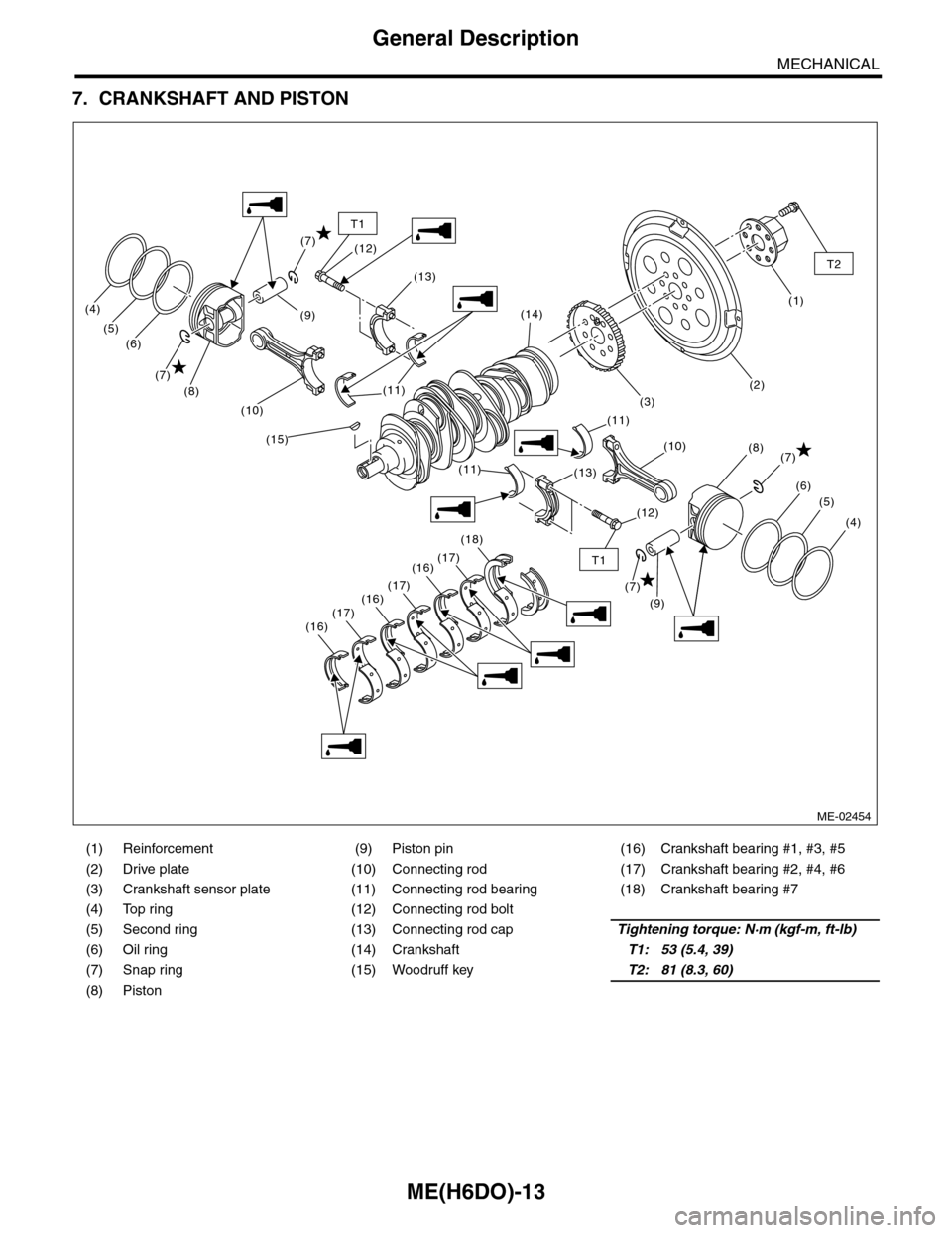
7. CRANKSHAFT AND PISTON
(1) Reinforcement (9) Piston pin (16) Crankshaft bearing #1, #3, #5
(2) Drive plate (10) Connecting rod (17) Crankshaft bearing #2, #4, #6
(3) Crankshaft sensor plate (11) Connecting rod bearing (18) Crankshaft bearing #7
(4) Top ring (12) Connecting rod bolt
(5) Second ring (13) Connecting rod capTightening torque: N·m (kgf-m, ft-lb)
(6) Oil ring (14) CrankshaftT1: 53 (5.4, 39)
(7) Snap ring (15) Woodruff keyT2: 81 (8.3, 60)
(8) Piston
(9)(1)
(3)
(2)
(4)
(5)
(6)
(7)(8)
(9)
(7)
(8)
(7)
(6)
(5)
(4)
(7)
(15)
(11)
(13)
(12)
(12)
(14)
(10)
(11)
(11)(13)
(18)
(16)(17)
(17)(16)(17)(16)
(10)
T1
T2
T1
ME-02454
Page 1880 of 2453
ME(H6DO)-14
General Description
MECHANICAL
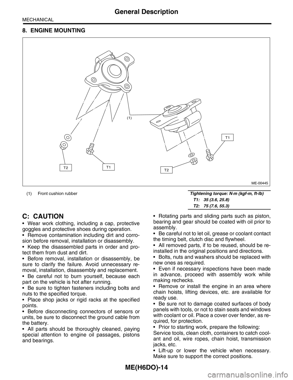
8. ENGINE MOUNTING
C: CAUTION
•Wear work clothing, including a cap, protective
goggles and protective shoes during operation.
•Remove contamination including dirt and corro-
sion before removal, installation or disassembly.
•Keep the disassembled parts in order and pro-
tect them from dust and dirt.
•Before removal, installation or disassembly, be
sure to clarify the failure. Avoid unnecessary re-
moval, installation, disassembly and replacement.
•Be careful not to burn yourself, because each
part on the vehicle is hot after running.
•Be sure to tighten fasteners including bolts and
nuts to the specified torque.
•Place shop jacks or rigid racks at the specified
points.
•Before disconnecting connectors of sensors or
units, be sure to disconnect the ground cable from
the battery.
•All parts should be thoroughly cleaned, paying
special attention to engine oil passages, pistons
and bearings.
•Rotating parts and sliding parts such as piston,
bearing and gear should be coated with oil prior to
assembly.
•Be careful not to let oil, grease or coolant contact
the timing belt, clutch disc and flywheel.
•All removed parts, if to be reused, should be re-
installed in the original positions and directions.
•Bolts, nuts and washers should be replaced with
new ones as required.
•Even if necessary inspections have been made
in advance, proceed with assembly work while
making rechecks.
•Remove or install the engine in an area where
chain hoists, lifting devices, etc. are available for
ready use.
•Be sure not to damage coated surfaces of body
panels with tools, or not to stain seats and windows
with coolant or oil. Place a cover over fender, as re-
quired, for protection.
•Prior to starting work, prepare the following:
Service tools, clean cloth, containers to catch cool-
ant and oil, wire ropes, chain hoist, transmission
jacks, etc.
•Lift-up or lower the vehicle when necessary.
Make sure to support the correct positions.
(1) Front cushion rubber Tightening torque: N·m (kgf-m, ft-lb)
T1: 35 (3.6, 25.8)
T2: 75 (7.6, 55.3)
(1)
T2
T1
T1T2
ME-00445