SUBARU TRIBECA 2009 1.G Service Workshop Manual
Manufacturer: SUBARU, Model Year: 2009, Model line: TRIBECA, Model: SUBARU TRIBECA 2009 1.GPages: 2453, PDF Size: 46.32 MB
Page 2071 of 2453
5AT-55
ATF Filter
AUTOMATIC TRANSMISSION
18.ATF Filter
A: REMOVAL
1) Remove the front bumper.
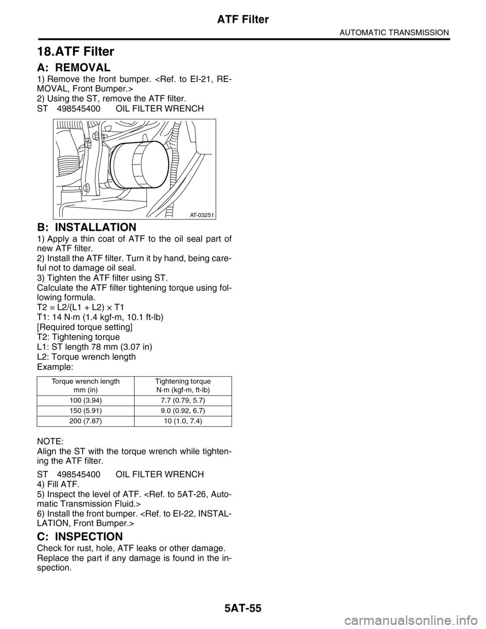
2) Using the ST, remove the ATF filter.
ST 498545400 OIL FILTER WRENCH
B: INSTALLATION
1) Apply a thin coat of ATF to the oil seal part of
new ATF filter.
2) Install the ATF filter. Turn it by hand, being care-
ful not to damage oil seal.
3) Tighten the ATF filter using ST.
Calculate the ATF filter tightening torque using fol-
lowing formula.
T2 = L2/(L1 + L2) × T1
T1: 14 N·m (1.4 kgf-m, 10.1 ft-lb)
[Required torque setting]
T2: Tightening torque
L1: ST length 78 mm (3.07 in)
L2: Torque wrench length
Example:
NOTE:
Align the ST with the torque wrench while tighten-
ing the ATF filter.
ST 498545400 OIL FILTER WRENCH
4) Fill ATF.
5) Inspect the level of ATF.
6) Install the front bumper.
C: INSPECTION
Check for rust, hole, ATF leaks or other damage.
Replace the part if any damage is found in the in-
spection.
To r q u e w r e n c h l e n g t h
mm (in)
Tightening torque
N·m (kgf-m, ft-lb)
100 (3.94) 7.7 (0.79, 5.7)
150 (5.91) 9.0 (0.92, 6.7)
200 (7.87) 10 (1.0, 7.4)
AT-03251
Page 2072 of 2453
5AT-56
Transmission Control Module (TCM)
AUTOMATIC TRANSMISSION
19.Transmission Control Mod-
ule (TCM)
A: REMOVAL
1) Disconnect the ground cable from battery.
2) Remove the lower cover and then disconnect
the connector.
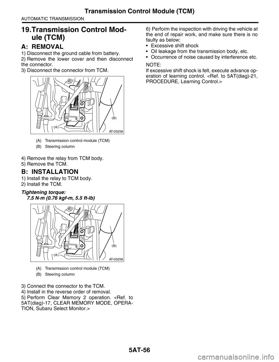
3) Disconnect the connector from TCM.
4) Remove the relay from TCM body.
5) Remove the TCM.
B: INSTALLATION
1) Install the relay to TCM body.
2) Install the TCM.
Tightening torque:
7.5 N·m (0.76 kgf-m, 5.5 ft-lb)
3) Connect the connector to the TCM.
4) Install in the reverse order of removal.
5) Perform Clear Memory 2 operation.
TION, Subaru Select Monitor.>
6) Perform the inspection with driving the vehicle at
the end of repair work, and make sure there is no
faulty as below;
•Excessive shift shock
•Oil leakage from the transmission body, etc.
•Occurrence of noise caused by interference etc.
NOTE:
If excessive shift shock is felt, execute advance op-
eration of learning control.
(A) Transmission control module (TCM)
(B) Steering column
(A) Transmission control module (TCM)
(B) Steering column
AT-03258(A)
(B)
AT-03258(A)
(B)
Page 2073 of 2453
5AT-57
ATF Cooler Pipe & Hose
AUTOMATIC TRANSMISSION
20.ATF Cooler Pipe & Hose
A: REMOVAL
1) Set the vehicle on a lift.
2) Lift-up the vehicle.
3) Remove the under cover.
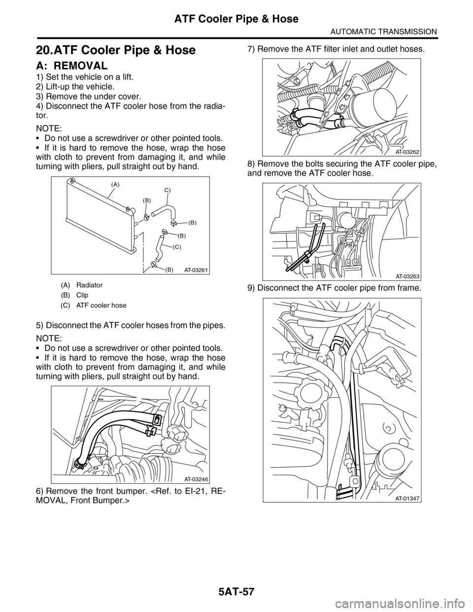
4) Disconnect the ATF cooler hose from the radia-
tor.
NOTE:
•Do not use a screwdriver or other pointed tools.
•If it is hard to remove the hose, wrap the hose
with cloth to prevent from damaging it, and while
turning with pliers, pull straight out by hand.
5) Disconnect the ATF cooler hoses from the pipes.
NOTE:
•Do not use a screwdriver or other pointed tools.
•If it is hard to remove the hose, wrap the hose
with cloth to prevent from damaging it, and while
turning with pliers, pull straight out by hand.
6) Remove the front bumper.
7) Remove the ATF filter inlet and outlet hoses.
8) Remove the bolts securing the ATF cooler pipe,
and remove the ATF cooler hose.
9) Disconnect the ATF cooler pipe from frame.(A) Radiator
(B) Clip
(C) ATF cooler hose
AT-03261
(A)
(B)
C)
(C)
(B)
(B)
(B)
AT-03246
AT-03262
AT-03263
AT-01347
Page 2074 of 2453
5AT-58
ATF Cooler Pipe & Hose
AUTOMATIC TRANSMISSION
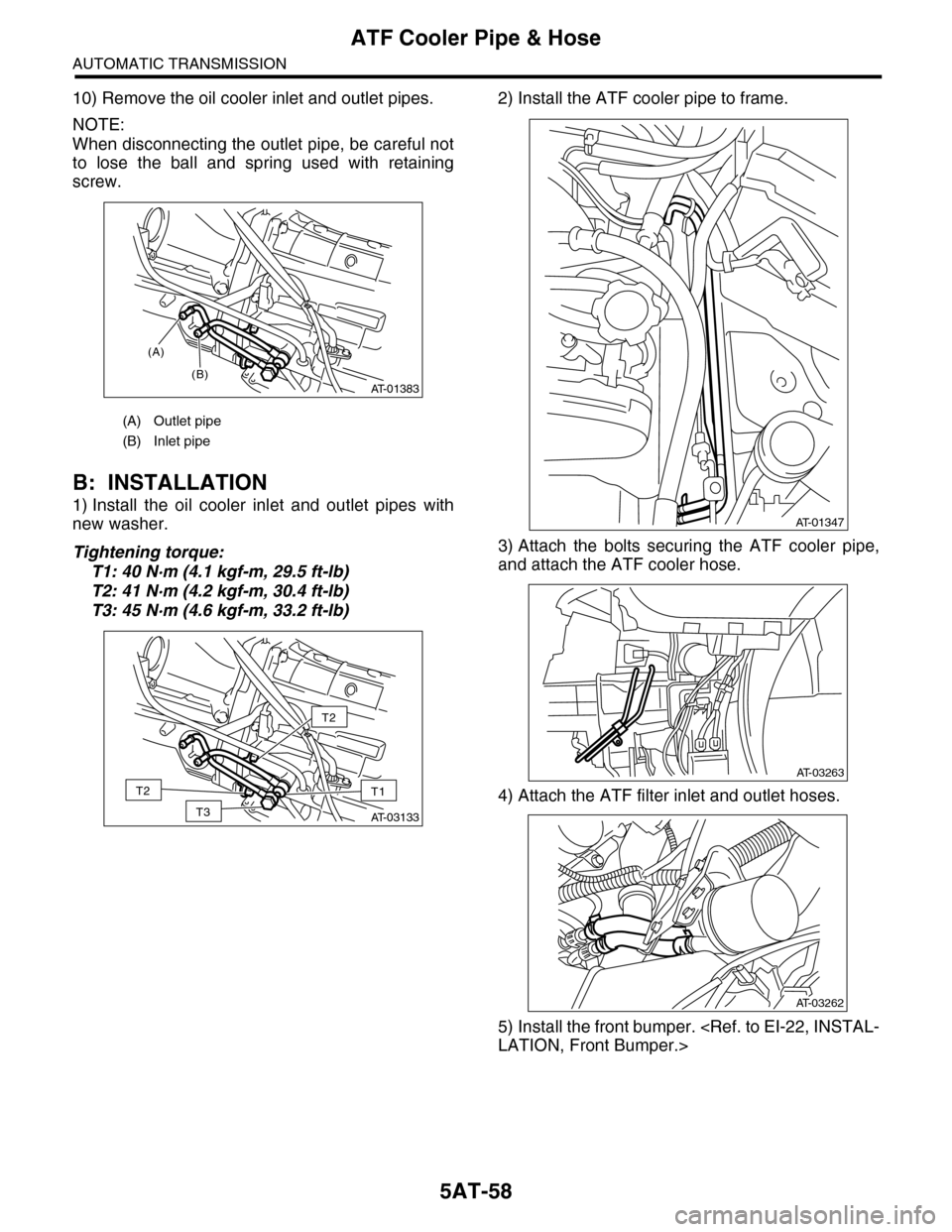
10) Remove the oil cooler inlet and outlet pipes.
NOTE:
When disconnecting the outlet pipe, be careful not
to lose the ball and spring used with retaining
screw.
B: INSTALLATION
1) Install the oil cooler inlet and outlet pipes with
new washer.
Tightening torque:
T1: 40 N·m (4.1 kgf-m, 29.5 ft-lb)
T2: 41 N·m (4.2 kgf-m, 30.4 ft-lb)
T3: 45 N·m (4.6 kgf-m, 33.2 ft-lb)
2) Install the ATF cooler pipe to frame.
3) Attach the bolts securing the ATF cooler pipe,
and attach the ATF cooler hose.
4) Attach the ATF filter inlet and outlet hoses.
5) Install the front bumper.
(A) Outlet pipe
(B) Inlet pipe
AT-01383
(A)
(B)
AT-03133
T2
T1 T2
T3
AT-01347
AT-03263
AT-03262
Page 2075 of 2453
5AT-59
ATF Cooler Pipe & Hose
AUTOMATIC TRANSMISSION
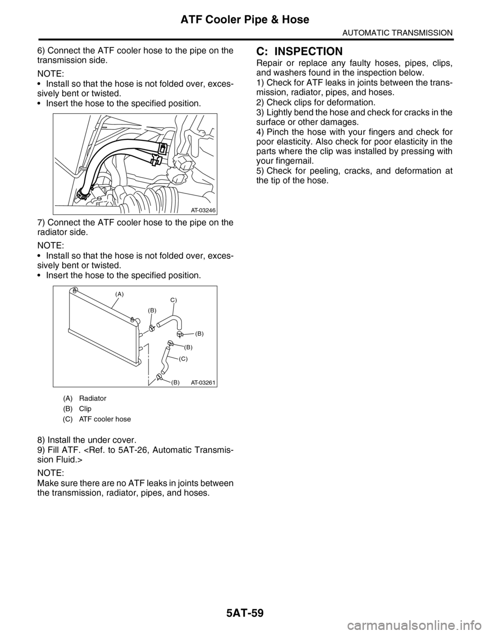
6) Connect the ATF cooler hose to the pipe on the
transmission side.
NOTE:
•Install so that the hose is not folded over, exces-
sively bent or twisted.
•Insert the hose to the specified position.
7) Connect the ATF cooler hose to the pipe on the
radiator side.
NOTE:
•Install so that the hose is not folded over, exces-
sively bent or twisted.
•Insert the hose to the specified position.
8) Install the under cover.
9) Fill ATF.
NOTE:
Make sure there are no ATF leaks in joints between
the transmission, radiator, pipes, and hoses.
C: INSPECTION
Repair or replace any faulty hoses, pipes, clips,
and washers found in the inspection below.
1) Check for ATF leaks in joints between the trans-
mission, radiator, pipes, and hoses.
2) Check clips for deformation.
3) Lightly bend the hose and check for cracks in the
surface or other damages.
4) Pinch the hose with your fingers and check for
poor elasticity. Also check for poor elasticity in the
parts where the clip was installed by pressing with
your fingernail.
5) Check for peeling, cracks, and deformation at
the tip of the hose.
(A) Radiator
(B) Clip
(C) ATF cooler hose
AT-03246
AT-03261
(A)
(B)
C)
(C)
(B)
(B)
(B)
Page 2076 of 2453
5AT-60
Air Breather Hose
AUTOMATIC TRANSMISSION
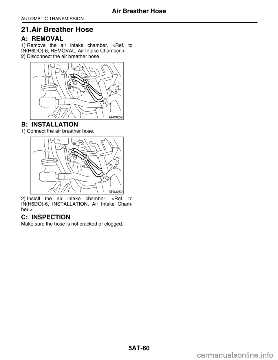
21.Air Breather Hose
A: REMOVAL
1) Remove the air intake chamber.
2) Disconnect the air breather hose.
B: INSTALLATION
1) Connect the air breather hose.
2) Install the air intake chamber.
ber.>
C: INSPECTION
Make sure the hose is not cracked or clogged.
AT-03252
AT-03252
Page 2077 of 2453
5AT-61
Oil Charge Pipe
AUTOMATIC TRANSMISSION
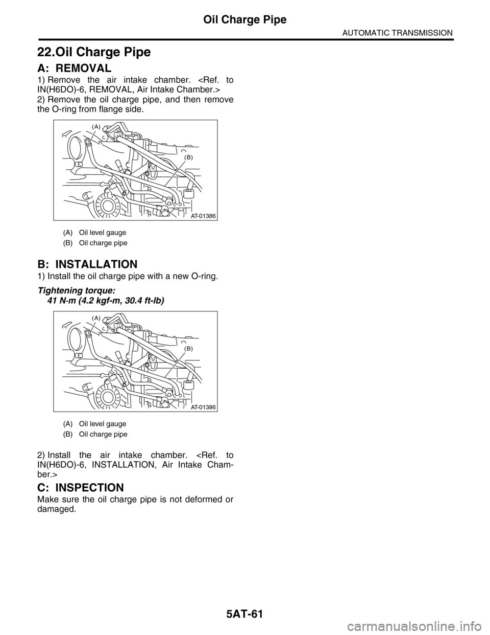
22.Oil Charge Pipe
A: REMOVAL
1) Remove the air intake chamber.
2) Remove the oil charge pipe, and then remove
the O-ring from flange side.
B: INSTALLATION
1) Install the oil charge pipe with a new O-ring.
Tightening torque:
41 N·m (4.2 kgf-m, 30.4 ft-lb)
2) Install the air intake chamber.
ber.>
C: INSPECTION
Make sure the oil charge pipe is not deformed or
damaged.
(A) Oil level gauge
(B) Oil charge pipe
(A) Oil level gauge
(B) Oil charge pipe
AT-01386
(B)
(A)
AT-01386
(B)
(A)
Page 2078 of 2453
5AT-62
Torque Converter Assembly
AUTOMATIC TRANSMISSION
23.Torque Converter Assembly
A: REMOVAL
1) Remove the transmission assembly from vehicle
body.
2) Pull out the torque converter and oil pump shaft
horizontally.
NOTE:
•Be sure not to scratch the inside of bushing in oil
pump shaft.
•Be careful that the oil pump shaft may drawn out
simultaneously.
3) Remove the oil pump shaft from torque convert-
er as necessary.
B: INSTALLATION
1) When the oil pump shaft is removed, install the
shaft to torque converter.
NOTE:
Make sure the clip is firmly inserted.
2) Install the oil pump shaft to torque converter, and
then make sure that the clip is secured on groove.
3) Apply ATF to the revolving and sliding surface of
the oil pump shaft.
4) Holding the torque converter assembly by hand,
lightly rotate it to engage with the oil pump rotor.
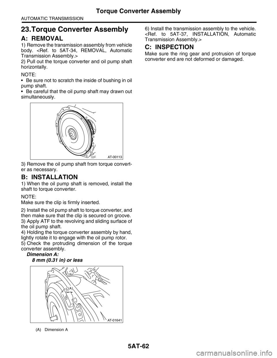
5) Check the protruding dimension of the torque
converter assembly.
Dimension A:
8 mm (0.31 in) or less
6) Install the transmission assembly to the vehicle.
C: INSPECTION
Make sure the ring gear and protrusion of torque
converter end are not deformed or damaged.
(A) Dimension A
AT-00113
AT-01641
(A)
Page 2079 of 2453
5AT-63
Extension Case
AUTOMATIC TRANSMISSION
24.Extension Case
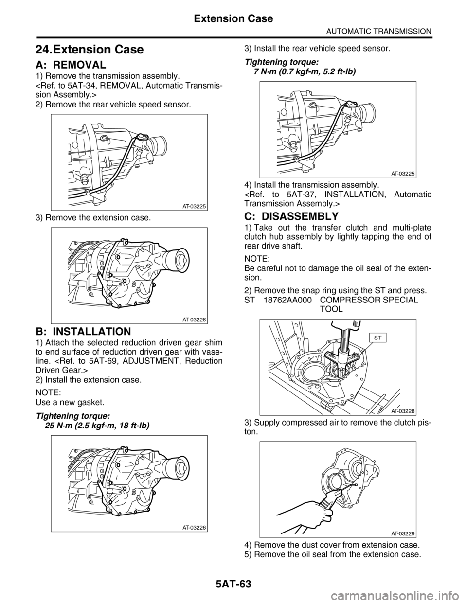
A: REMOVAL
1) Remove the transmission assembly.
2) Remove the rear vehicle speed sensor.
3) Remove the extension case.
B: INSTALLATION
1) Attach the selected reduction driven gear shim
to end surface of reduction driven gear with vase-
line.
2) Install the extension case.
NOTE:
Use a new gasket.
Tightening torque:
25 N·m (2.5 kgf-m, 18 ft-lb)
3) Install the rear vehicle speed sensor.
Tightening torque:
7 N·m (0.7 kgf-m, 5.2 ft-lb)
4) Install the transmission assembly.
C: DISASSEMBLY
1) Take out the transfer clutch and multi-plate
clutch hub assembly by lightly tapping the end of
rear drive shaft.
NOTE:
Be careful not to damage the oil seal of the exten-
sion.
2) Remove the snap ring using the ST and press.
ST 18762AA000 COMPRESSOR SPECIAL
TOOL
3) Supply compressed air to remove the clutch pis-
ton.
4) Remove the dust cover from extension case.
5) Remove the oil seal from the extension case.
AT-03225
AT-03226
AT-03226
AT-03225
AT-03228
ST
AT-03229
Page 2080 of 2453
5AT-64
Extension Case
AUTOMATIC TRANSMISSION
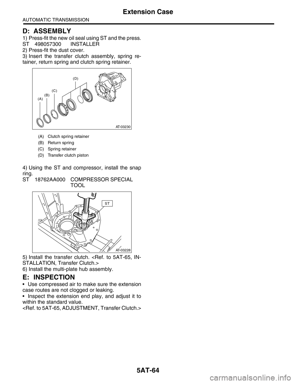
D: ASSEMBLY
1) Press-fit the new oil seal using ST and the press.
ST 498057300 INSTALLER
2) Press-fit the dust cover.
3) Insert the transfer clutch assembly, spring re-
tainer, return spring and clutch spring retainer.
4) Using the ST and compressor, install the snap
ring.
ST 18762AA000 COMPRESSOR SPECIAL
TOOL
5) Install the transfer clutch.
6) Install the multi-plate hub assembly.
E: INSPECTION
•Use compressed air to make sure the extension
case routes are not clogged or leaking.
•Inspect the extension end play, and adjust it to
within the standard value.
(A) Clutch spring retainer
(B) Return spring
(C) Spring retainer
(D) Transfer clutch piston
AT-03230
(A)(B)(C)
(D)
AT-03228
ST