wheel torque SUBARU TRIBECA 2009 1.G Service Owner's Manual
[x] Cancel search | Manufacturer: SUBARU, Model Year: 2009, Model line: TRIBECA, Model: SUBARU TRIBECA 2009 1.GPages: 2453, PDF Size: 46.32 MB
Page 846 of 2453
DS-29
Rear Drive Shaft
DRIVE SHAFT SYSTEM
7) Install the wheel.
Tightening torque:
110 N·m (11.2 kgf-m, 81.1 ft-lb)
C: DISASSEMBLY
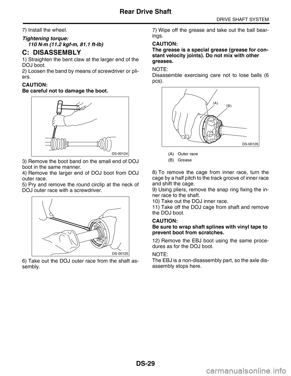
1) Straighten the bent claw at the larger end of the
DOJ boot.
2) Loosen the band by means of screwdriver or pli-
ers.
CAUTION:
Be careful not to damage the boot.
3) Remove the boot band on the small end of DOJ
boot in the same manner.
4) Remove the larger end of DOJ boot from DOJ
outer race.
5) Pry and remove the round circlip at the neck of
DOJ outer race with a screwdriver.
6) Take out the DOJ outer race from the shaft as-
sembly.
7) Wipe off the grease and take out the ball bear-
ings.
CAUTION:
The grease is a special grease (grease for con-
stant velocity joints). Do not mix with other
greases.
NOTE:
Disassemble exercising care not to lose balls (6
pcs).
8) To remove the cage from inner race, turn the
cage by a half pitch to the track groove of inner race
and shift the cage.
9) Using pliers, remove the snap ring fixing the in-
ner race to the shaft.
10) Take out the DOJ inner race.
11) Take off the DOJ cage from shaft and remove
the DOJ boot.
CAUTION:
Be sure to wrap shaft splines with vinyl tape to
prevent boot from scratches.
12) Remove the EBJ boot using the same proce-
dures as for the DOJ boot.
NOTE:
The EBJ is a non-disassembly part, so the axle dis-
assembly stops here.
DS-00124
DS-00125
(A) Outer race
(B) Grease
DS-00126
(B)(A)
Page 857 of 2453
FS-9
Wheel Alignment
FRONT SUSPENSION
4) Tighten two new self–locking nuts.
Tightening torque:
175 N·m (17.9 kgf-m, 129 ft-lb)
3. CASTER
•INSPECTION
1) Place the front wheel on the turning radius
gauge. Make sure the ground contact surfaces of
front and rear wheels are at the same height.
2) Set the adapter at the center of wheel, and then
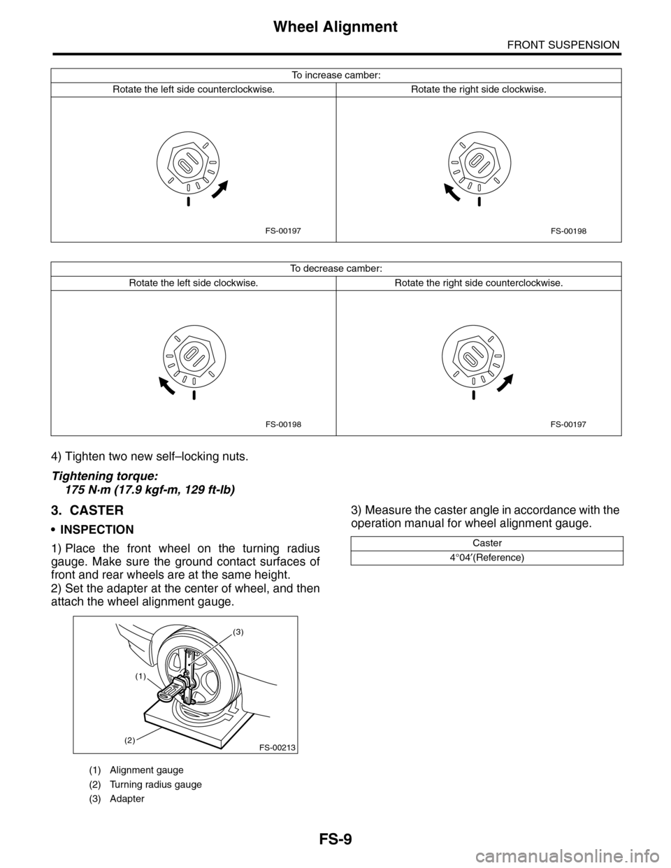
attach the wheel alignment gauge.
3) Measure the caster angle in accordance with the
operation manual for wheel alignment gauge.
To i n c r e a s e c a m b e r :
Rotate the left side counterclockwise. Rotate the right side clockwise.
To d e c r e a s e c a m b e r :
Rotate the left side clockwise. Rotate the right side counterclockwise.
FS-00197FS-00198
FS-00198FS-00197
(1) Alignment gauge
(2) Turning radius gauge
(3) Adapter
FS-00213
(1)
(2)
(3)
Caster
4°04′(Reference)
Page 858 of 2453
FS-10
Wheel Alignment
FRONT SUSPENSION
4. STEERING ANGLE
•INSPECTION
•ADJUSTMENT
1) Turn the tie-rod to adjust the steering angle of
both inner and outer wheels.
2) Check the toe–in.
NOTE:
Correct the boot if it is twisted.
5. FRONT WHEEL TOE–IN
•INSPECTION
Toe-in:
0±3 mm (0±0.12 in)
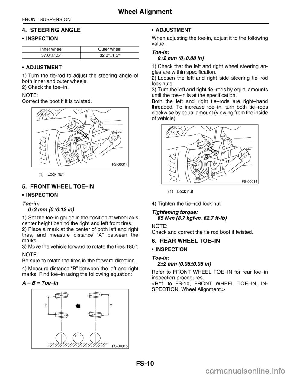
1) Set the toe-in gauge in the position at wheel axis
center height behind the right and left front tires.
2) Place a mark at the center of both left and right
tires, and measure distance “A” between the
marks.
3) Move the vehicle forward to rotate the tires 180°.
NOTE:
Be sure to rotate the tires in the forward direction.
4) Measure distance “B” between the left and right
marks. Find toe–in using the following equation:
A – B = Toe–in
•ADJUSTMENT
When adjusting the toe-in, adjust it to the following
value.
Toe-in:
0±2 mm (0±0.08 in)
1) Check that the left and right wheel steering an-
gles are within specification.
2) Loosen the left and right side steering tie–rod
lock nuts.
3) Turn the left and right tie–rods by equal amounts
until the toe–in is at the specification.
Both the left and right tie–rods are right–hand
threaded. To increase toe–in, turn both tie–rods
clockwise by equal amount (viewing from the inside
of vehicle).
4) Tighten the tie–rod lock nut.
Tightening torque:
85 N·m (8.7 kgf-m, 62.7 ft-lb)
NOTE:
Check and correct the tie rod boot if twisted.
6. REAR WHEEL TOE–IN
•INSPECTION
Toe-in:
2±2 mm (0.08±0.08 in)
Refer to FRONT WHEEL TOE–IN for rear toe–in
inspection procedures.
Inner wheel Outer wheel
37.0°±1.5° 32.0°±1.5°
(1) Lock nut
FS-00014
(1)
FS-00015
AB
(1) Lock nut
FS-00014
(1)
Page 859 of 2453
FS-11
Wheel Alignment
FRONT SUSPENSION
•ADJUSTMENT
When adjusting, adjust it to the following value.
Toe-in:
2±1.5 mm (0.08±0.06 in)
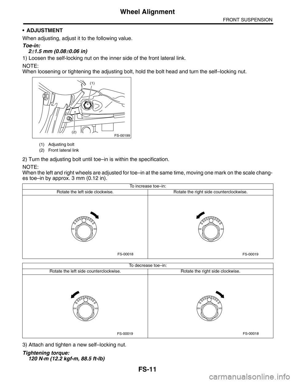
1) Loosen the self-locking nut on the inner side of the front lateral link.
NOTE:
When loosening or tightening the adjusting bolt, hold the bolt head and turn the self–locking nut.
2) Turn the adjusting bolt until toe–in is within the specification.
NOTE:
When the left and right wheels are adjusted for toe–in at the same time, moving one mark on the scale chang-
es toe–in by approx. 3 mm (0.12 in).
3) Attach and tighten a new self–locking nut.
Tightening torque:
120 N·m (12.2 kgf-m, 88.5 ft-lb)
(1) Adjusting bolt
(2) Front lateral link
FS-00199
(1)
(2)
To i n c r e a s e t o e – i n :
Rotate the left side clockwise. Rotate the right side counterclockwise.
To d e c r e a s e t o e – i n :
Rotate the left side counterclockwise. Rotate the right side clockwise.
FS-00018FS-00019
FS-00019FS-00018
Page 862 of 2453
FS-14
Front Stabilizer
FRONT SUSPENSION
4. Front Stabilizer
A: REMOVAL
1) Lift-up the vehicle, and then remove the front
wheels.
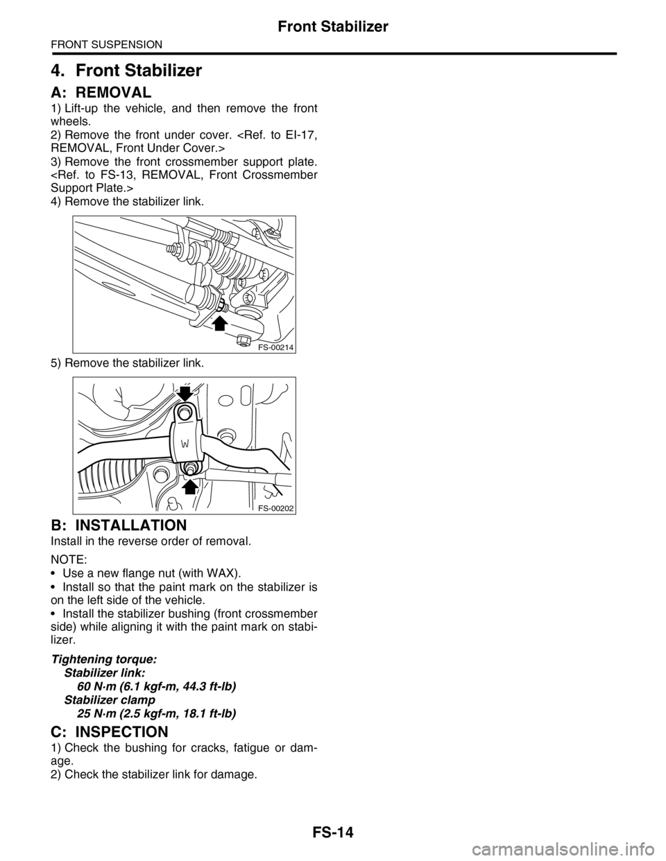
2) Remove the front under cover.
3) Remove the front crossmember support plate.
4) Remove the stabilizer link.
5) Remove the stabilizer link.
B: INSTALLATION
Install in the reverse order of removal.
NOTE:
•Use a new flange nut (with WAX).
•Install so that the paint mark on the stabilizer is
on the left side of the vehicle.
•Install the stabilizer bushing (front crossmember
side) while aligning it with the paint mark on stabi-
lizer.
Tightening torque:
Stabilizer link:
60 N·m (6.1 kgf-m, 44.3 ft-lb)
Stabilizer clamp
25 N·m (2.5 kgf-m, 18.1 ft-lb)
C: INSPECTION
1) Check the bushing for cracks, fatigue or dam-
age.
2) Check the stabilizer link for damage.
FS-00214
FS-00202
Page 863 of 2453
FS-15
Front Ball Joint
FRONT SUSPENSION
5. Front Ball Joint
A: REMOVAL
1) Lift-up the vehicle, and remove the front wheels.
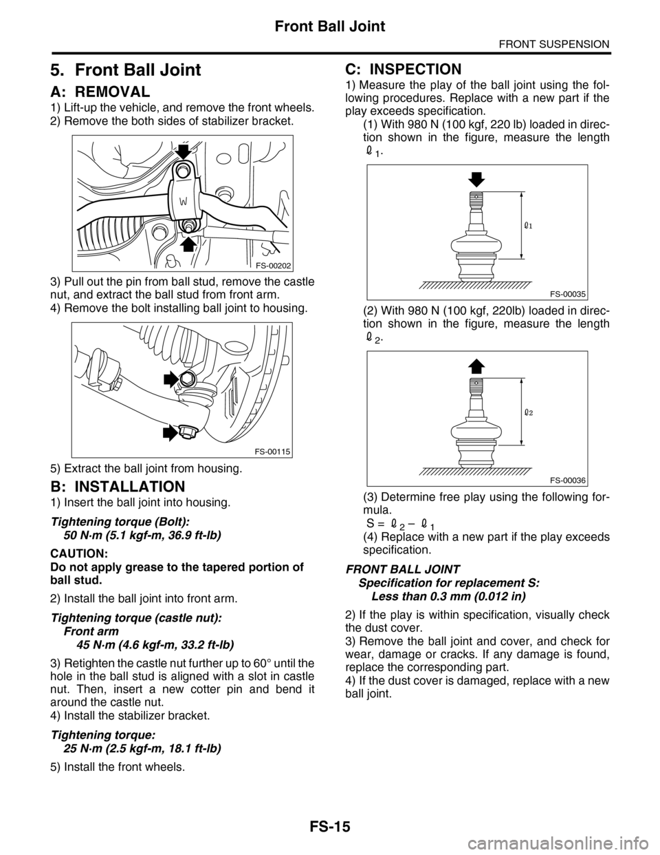
2) Remove the both sides of stabilizer bracket.
3) Pull out the pin from ball stud, remove the castle
nut, and extract the ball stud from front arm.
4) Remove the bolt installing ball joint to housing.
5) Extract the ball joint from housing.
B: INSTALLATION
1) Insert the ball joint into housing.
Tightening torque (Bolt):
50 N·m (5.1 kgf-m, 36.9 ft-lb)
CAUTION:
Do not apply grease to the tapered portion of
ball stud.
2) Install the ball joint into front arm.
Tightening torque (castle nut):
Front arm
45 N·m (4.6 kgf-m, 33.2 ft-lb)
3) Retighten the castle nut further up to 60° until the
hole in the ball stud is aligned with a slot in castle
nut. Then, insert a new cotter pin and bend it
around the castle nut.
4) Install the stabilizer bracket.
Tightening torque:
25 N·m (2.5 kgf-m, 18.1 ft-lb)
5) Install the front wheels.
C: INSPECTION
1) Measure the play of the ball joint using the fol-
lowing procedures. Replace with a new part if the
play exceeds specification.
(1) With 980 N (100 kgf, 220 lb) loaded in direc-
tion shown in the figure, measure the length
21.
(2) With 980 N (100 kgf, 220lb) loaded in direc-
tion shown in the figure, measure the length
22.
(3) Determine free play using the following for-
mula.
S = 22 – 21(4) Replace with a new part if the play exceeds
specification.
FRONT BALL JOINT
Specification for replacement S:
Less than 0.3 mm (0.012 in)
2) If the play is within specification, visually check
the dust cover.
3) Remove the ball joint and cover, and check for
wear, damage or cracks. If any damage is found,
replace the corresponding part.
4) If the dust cover is damaged, replace with a new
ball joint.
FS-00202
FS-00115
FS-00035
FS-00036
Page 864 of 2453
FS-16
Front Arm
FRONT SUSPENSION
6. Front Arm
A: REMOVAL
1) Lift-up the vehicle, and then remove the front
wheels.
2) Remove the front crossmember support plate.
3) Remove the front stabilizer.
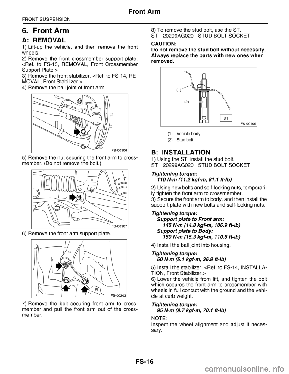
4) Remove the ball joint of front arm.
5) Remove the nut securing the front arm to cross-
member. (Do not remove the bolt.)
6) Remove the front arm support plate.
7) Remove the bolt securing front arm to cross-
member and pull the front arm out of the cross-
member.
8) To remove the stud bolt, use the ST.
ST 20299AG020 STUD BOLT SOCKET
CAUTION:
Do not remove the stud bolt without necessity.
Always replace the parts with new ones when
removed.
B: INSTALLATION
1) Using the ST, install the stud bolt.
ST 20299AG020 STUD BOLT SOCKET
Tightening torque:
110 N·m (11.2 kgf-m, 81.1 ft-lb)
2) Using new bolts and self-locking nuts, temporari-
ly tighten the front arm to crossmember.
3) Secure the front arm to body, and then install the
support plate with new bolts and self-locking nuts.
Tightening torque:
Support plate to Front arm:
145 N·m (14.8 kgf-m, 106.9 ft-lb)
Support plate to Body:
150 N·m (15.3 kgf-m, 110.6 ft-lb)
4) Install the ball joint into housing.
Tightening torque:
50 N·m (5.1 kgf-m, 36.9 ft-lb)
5) Install the stabilizer.
6) Lower the vehicle from lift, and tighten the bolt
which secures the front arm to crossmember with
wheels in full contact with the ground and the vehi-
cle at curb weight.
Tightening torque:
95 N·m (9.7 kgf-m, 70.1 ft-lb)
NOTE:
Inspect the wheel alignment and adjust if neces-
sary.
FS-00106
FS-00107
FS-00203
(1) Vehicle body
(2) Stud bolt
FS-00109
(2)
(1)
ST
Page 867 of 2453
FS-19
Front Strut
FRONT SUSPENSION
7. Front Strut
A: REMOVAL
1) Lift-up the vehicle, and then remove the front
wheels.
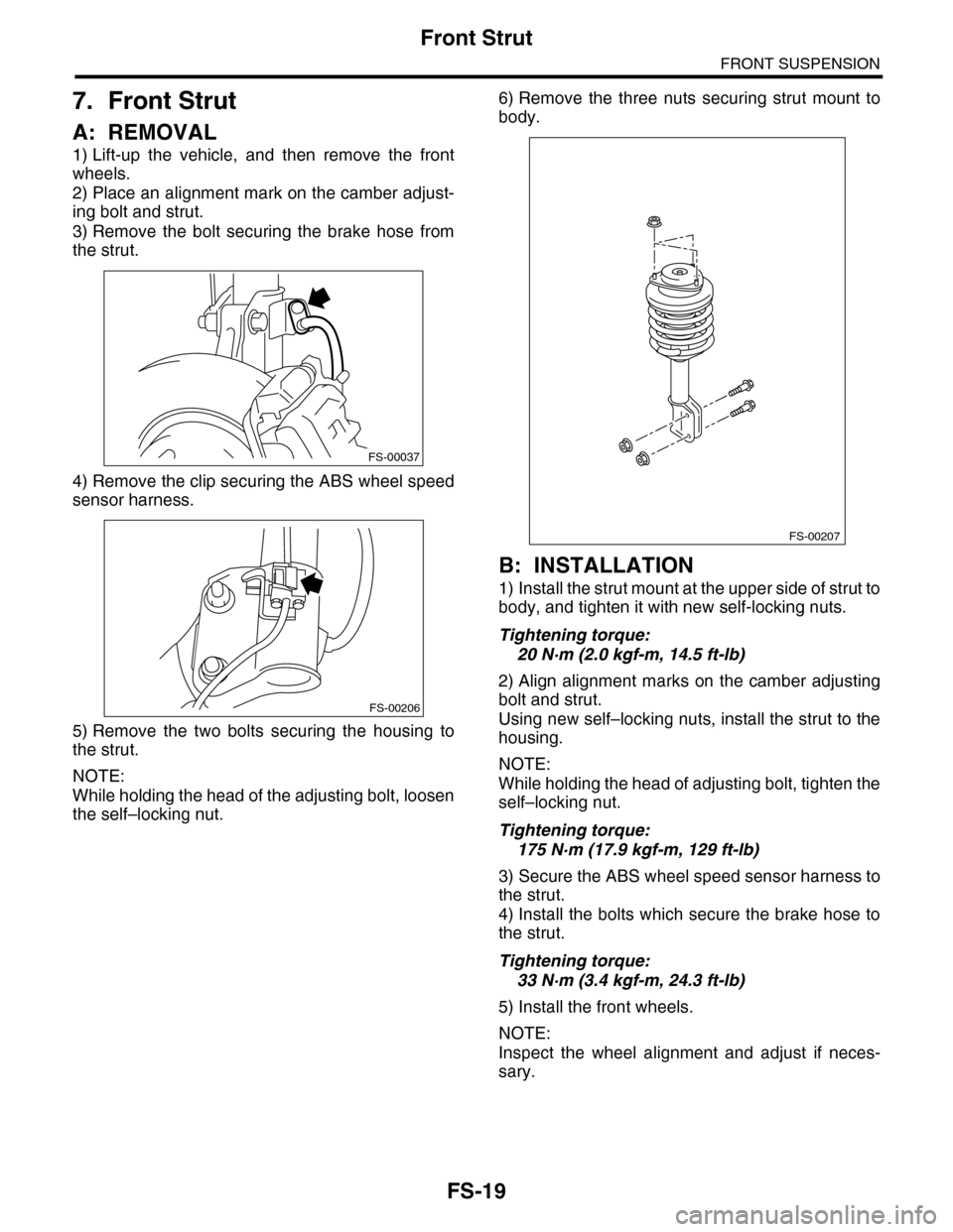
2) Place an alignment mark on the camber adjust-
ing bolt and strut.
3) Remove the bolt securing the brake hose from
the strut.
4) Remove the clip securing the ABS wheel speed
sensor harness.
5) Remove the two bolts securing the housing to
the strut.
NOTE:
While holding the head of the adjusting bolt, loosen
the self–locking nut.
6) Remove the three nuts securing strut mount to
body.
B: INSTALLATION
1) Install the strut mount at the upper side of strut to
body, and tighten it with new self-locking nuts.
Tightening torque:
20 N·m (2.0 kgf-m, 14.5 ft-lb)
2) Align alignment marks on the camber adjusting
bolt and strut.
Using new self–locking nuts, install the strut to the
housing.
NOTE:
While holding the head of adjusting bolt, tighten the
self–locking nut.
Tightening torque:
175 N·m (17.9 kgf-m, 129 ft-lb)
3) Secure the ABS wheel speed sensor harness to
the strut.
4) Install the bolts which secure the brake hose to
the strut.
Tightening torque:
33 N·m (3.4 kgf-m, 24.3 ft-lb)
5) Install the front wheels.
NOTE:
Inspect the wheel alignment and adjust if neces-
sary.
FS-00037
FS-00206
FS-00207
Page 871 of 2453
FS-23
Front Crossmember
FRONT SUSPENSION
8. Front Crossmember
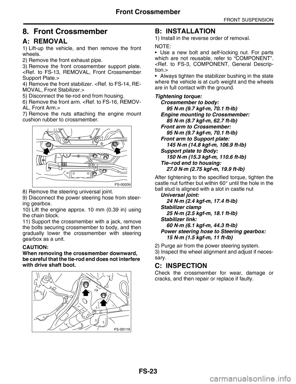
A: REMOVAL
1) Lift-up the vehicle, and then remove the front
wheels.
2) Remove the front exhaust pipe.
3) Remove the front crossmember support plate.
4) Remove the front stabilizer.
5) Disconnect the tie-rod end from housing.
6) Remove the front arm.
7) Remove the nuts attaching the engine mount
cushion rubber to crossmember.
8) Remove the steering universal joint.
9) Disconnect the power steering hose from steer-
ing gearbox.
10) Lift the engine approx. 10 mm (0.39 in) using
the chain block.
11) Support the crossmember with a jack, remove
the bolts securing crossmember to body, and then
gradually lower the crossmember with steering
gearbox as a unit.
CAUTION:
When removing the crossmember downward,
be careful that the tie-rod end does not interfere
with drive shaft boot.
B: INSTALLATION
1) Install in the reverse order of removal.
NOTE:
•Use a new bolt and self-locking nut. For parts
which are not reusable, refer to “COMPONENT”.
•Always tighten the stabilizer bushing in the state
where the vehicle is at curb weight and the wheels
are in full contact with the ground.
Tightening torque:
Crossmember to body:
95 N·m (9.7 kgf-m, 70.1 ft-lb)
Engine mounting to Crossmember:
85 N·m (8.7 kgf-m, 62.7 ft-lb)
Front arm to Crossmember:
95 N·m (9.7 kgf-m, 70.1 ft-lb)
Front arm to Support plate:
145 N·m (14.8 kgf-m, 106.9 ft-lb)
Support plate to Body:
150 N·m (15.3 kgf-m, 110.6 ft-lb)
Tie–rod end to housing:
27.0 N·m (2.75 kgf-m, 19.9 ft-lb)
After tightening to the specified torque, tighten the
castle nut further but within 60° until the hole in the
ball stud is aligned with a slot in castle nut
Universal joint:
24 N·m (2.4 kgf-m, 17.4 ft-lb)
Stabilizer clamp
25 N·m (2.5 kgf-m, 18.1 ft-lb)
Stabilizer link:
60 N·m (6.1 kgf-m, 44.3 ft-lb)
Power steering hose to Steering gearbox:
15 N·m (1.5 kgf-m, 11 ft-lb)
2) Purge air from the power steering system.
3) Inspect the wheel alignment and adjust if neces-
sary.
C: INSPECTION
Check the crossmember for wear, damage or
cracks, and then repair or replace if faulty.
FS-00209
FS-00119
Page 872 of 2453
FS-24
General Diagnostic Table
FRONT SUSPENSION
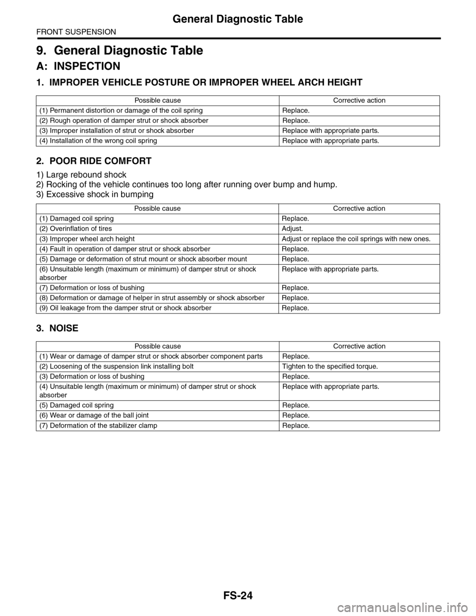
9. General Diagnostic Table
A: INSPECTION
1. IMPROPER VEHICLE POSTURE OR IMPROPER WHEEL ARCH HEIGHT
2. POOR RIDE COMFORT
1) Large rebound shock
2) Rocking of the vehicle continues too long after running over bump and hump.
3) Excessive shock in bumping
3. NOISE
Po ss ibl e c a us e C o r r e ct ive ac ti o n
(1) Permanent distortion or damage of the coil spring Replace.
(2) Rough operation of damper strut or shock absorber Replace.
(3) Improper installation of strut or shock absorber Replace with appropriate parts.
(4) Installation of the wrong coil spring Replace with appropriate parts.
Po ss ibl e ca us e C or r e ct i ve a ct io n
(1) Damaged coil spring Replace.
(2) Overinflation of tires Adjust.
(3) Improper wheel arch height Adjust or replace the coil springs with new ones.
(4) Fault in operation of damper strut or shock absorber Replace.
(5) Damage or deformation of strut mount or shock absorber mount Replace.
(6) Unsuitable length (maximum or minimum) of damper strut or shock
absorber
Replace with appropriate parts.
(7) Deformation or loss of bushing Replace.
(8) Deformation or damage of helper in strut assembly or shock absorber Replace.
(9) Oil leakage from the damper strut or shock absorber Replace.
Po ss ibl e c a us e C o r r e ct ive ac ti o n
(1) Wear or damage of damper strut or shock absorber component parts Replace.
(2) Loosening of the suspension link installing bolt Tighten to the specified torque.
(3) Deformation or loss of bushing Replace.
(4) Unsuitable length (maximum or minimum) of damper strut or shock
absorber
Replace with appropriate parts.
(5) Damaged coil spring Replace.
(6) Wear or damage of the ball joint Replace.
(7) Deformation of the stabilizer clamp Replace.