wheel torque SUBARU TRIBECA 2009 1.G Service Repair Manual
[x] Cancel search | Manufacturer: SUBARU, Model Year: 2009, Model line: TRIBECA, Model: SUBARU TRIBECA 2009 1.GPages: 2453, PDF Size: 46.32 MB
Page 2004 of 2453
PM-21
Brake Fluid
PERIODIC MAINTENANCE SERVICES
14.Brake Fluid
A: REPLACEMENT
1) Either jack-up the vehicle and place a rigid rack
under it, or lift-up the vehicle.
2) Remove all the wheels.
3) Drain the brake fluid from master cylinder.
4) Refill the reservoir tank with recommended
brake fluid.
Recommended brake fluid:
Refer to “RM” section.
ed Materials.>
NOTE:
•Avoid mixing different brands of brake fluid to
prevent degrading the quality of fluid.
•Be careful not to allow dirt or dust to get into the
reservoir tank.
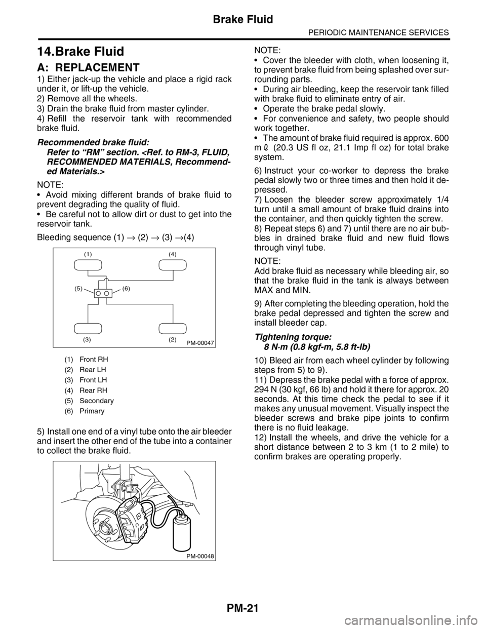
Bleeding sequence (1) → (2) → (3) →(4)
5) Install one end of a vinyl tube onto the air bleeder
and insert the other end of the tube into a container
to collect the brake fluid.
NOTE:
•Cover the bleeder with cloth, when loosening it,
to prevent brake fluid from being splashed over sur-
rounding parts.
•During air bleeding, keep the reservoir tank filled
with brake fluid to eliminate entry of air.
•Operate the brake pedal slowly.
•For convenience and safety, two people should
work together.
•The amount of brake fluid required is approx. 600
m2 (20.3 US fl oz, 21.1 Imp fl oz) for total brake
system.
6) Instruct your co-worker to depress the brake
pedal slowly two or three times and then hold it de-
pressed.
7) Loosen the bleeder screw approximately 1/4
turn until a small amount of brake fluid drains into
the container, and then quickly tighten the screw.
8) Repeat steps 6) and 7) until there are no air bub-
bles in drained brake fluid and new fluid flows
through vinyl tube.
NOTE:
Add brake fluid as necessary while bleeding air, so
that the brake fluid in the tank is always between
MAX and MIN.
9) After completing the bleeding operation, hold the
brake pedal depressed and tighten the screw and
install bleeder cap.
Tightening torque:
8 N·m (0.8 kgf-m, 5.8 ft-lb)
10) Bleed air from each wheel cylinder by following
steps from 5) to 9).
11) Depress the brake pedal with a force of approx.
294 N (30 kgf, 66 lb) and hold it there for approx. 20
seconds. At this time check the pedal to see if it
makes any unusual movement. Visually inspect the
bleeder screws and brake pipe joints to confirm
there is no fluid leakage.
12) Install the wheels, and drive the vehicle for a
short distance between 2 to 3 km (1 to 2 mile) to
confirm brakes are operating properly.
(1) Front RH
(2) Rear LH
(3) Front LH
(4) Rear RH
(5) Secondary
(6) Primary
(1) (4)
(2)(3)
(5) (6)
PM-00047
PM-00048
Page 2008 of 2453
PM-25
Suspension
PERIODIC MAINTENANCE SERVICES
4. WHEEL ALIGNMENT OF FRONT SUS-
PENSION
1) Check the alignment of front suspension to en-
sure that following items conform to standard val-
ues.
•Toe-in
•Camber
•Caster
•Steering angle
2) When the caster angle does not conform to ref-
erence obviously, visually inspect the following
components and replace deformed parts.
•Suspension components [Strut assembly, cross-
member, front arm, etc.]
•Parts connecting suspension and body
3) When the toe-in and camber are out of standard
value, adjust them so that they conform to standard
value.
4) When the right-and-left turning angles of tire are
out of standard, adjust to standard value.
5. WHEEL ALIGNMENT OF REAR SUS-
PENSION
1) Check the alignment of rear suspension to en-
sure that following items are within standard val-
ues.
•Toe-in
•Camber
•Thrust angle
2) When the camber angle does not conform to
standard value, visually inspect the following com-
ponents. If the deformation is observed, replace the
damaged parts.
•Suspension components [Shock absorber, rear
upper arm, front lateral link, rear lateral link, rear
trailing link, sub frame]
•Parts connecting suspension and body
3) When the toe-in and thrust angle are out of stan-
dard value, adjust them so that they conform to
standard value.
6. OIL LEAKAGE OF STRUT AND SHOCK
ABSORBER
Visually inspect the front strut and rear shock ab-
sorber for oil leakage. Replace the front strut and
rear shock absorber if oil leaks excessively.
7. TIGHTNESS OF BOLTS AND NUTS
Check the bolts and nuts for looseness. Retighten
the bolts and nuts to specified torque. If the self-
locking nuts and bolts are removed, replace them
with new ones.
•Front suspension
•Rear suspension
8. DAMAGE TO SUSPENSION PARTS
Check the following parts and the fastening portion
of the vehicle body for deformation or excessive
rusting which impairs the suspension. If necessary,
replace the damaged parts with new ones. If minor
rust formation, pitting, etc. are noted, remove the
rust and take rust prevention measure.
•Front suspension
•Front arm
•Crossmember
•Strut
•Rear suspension
•Upper arm
•Front lateral link
•Rear lateral link
•Rear trailing link
•Rear sub frame
•Shock absorber
•In the area where salt is sprayed to melt snow on
a road in winter, check suspension parts for dam-
age caused by rust every 12 months after lapse of
60 months. Take rust prevention measures as re-
quired.
Page 2012 of 2453
PM-29
Steering System (Power Steering)
PERIODIC MAINTENANCE SERVICES
21.Steering System (Power
Steering)
A: INSPECTION
1. STEERING WHEEL
1) Set the steering wheel in a straight-ahead posi-
tion, and check the wheel spokes to make sure
they are correctly set in their specified positions.
2) Lightly turn the steering wheel to the left and
right to determine the point where front wheels start
to move.
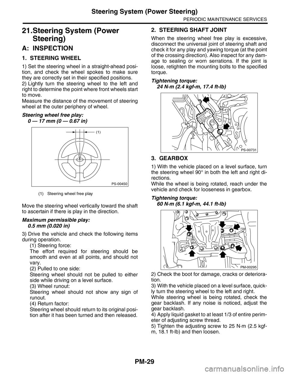
Measure the distance of the movement of steering
wheel at the outer periphery of wheel.
Steering wheel free play:
0 — 17 mm (0 — 0.67 in)
Move the steering wheel vertically toward the shaft
to ascertain if there is play in the direction.
Maximum permissible play:
0.5 mm (0.020 in)
3) Drive the vehicle and check the following items
during operation.
(1) Steering force:
The effort required for steering should be
smooth and even at all points, and should not
vary.
(2) Pulled to one side:
Steering wheel should not be pulled to either
side while driving on a level surface.
(3) Wheel runout:
Steering wheel should not show any sign of
runout.
(4) Return factor:
Steering wheel should return to its original posi-
tion after it has been turned and then released.
2. STEERING SHAFT JOINT
When the steering wheel free play is excessive,
disconnect the universal joint of steering shaft and
check it for any play and yawing torque (at the point
of the crossing direction). Also inspect for any dam-
age to sealing or worn serrations. If the joint is
loose, retighten the mounting bolts to the specified
torque.
Tightening torque:
24 N·m (2.4 kgf-m, 17.4 ft-lb)
3. GEARBOX
1) With the vehicle placed on a level surface, turn
the steering wheel 90° in both the left and right di-
rections.
While the wheel is being rotated, reach under the
vehicle and check for looseness in gearbox.
Tightening torque:
60 N·m (6.1 kgf-m, 44.1 ft-lb)
2) Check the boot for damage, cracks or deteriora-
tion.
3) With the vehicle placed on a level surface, quick-
ly turn the steering wheel to the left and right.
While steering wheel is being rotated, check the
gear backlash. If any noise is noticed, adjust the
gear backlash.
4) Apply liquid gasket to at least 1/3 of entire perim-
eter of adjusting screw thread.
5) Tighten the adjusting screw to 25 N·m (2.5 kgf-
m, 18.1 ft-lb) and then loosen.
(1) Steering wheel free play
(1)
PS-00450
PS-00731
PM-00295
Page 2046 of 2453
5AT-30
Stall Test
AUTOMATIC TRANSMISSION
5. Stall Test
A: INSPECTION
NOTE:
The stall test is extremely important in diagnosing
the condition of an automatic transmission and en-
gine. It should be conducted to measure the engine
stall speeds in “R” and “2nd of manual mode”.
Purposes of the stall test:
•Operational check of the automatic transmission
clutch
•Operational check of the torque converter clutch
•Engine performance check
1) Check that the throttle valve fully opens.
2) Check that the engine oil level is correct.
3) Check that the coolant level is correct.
4) Check that the ATF level is correct.
5) Check that the differential gear oil level is cor-
rect.
6) Raise the ATF temperature to 70 to 80°C (158 to
176°F) by driving a distance of 5 to 10 km (3 to 6
miles). Confirm the ATF temperature on Subaru
Select Monitor.
tor.>
7) Place the wheel chocks at the front and rear of
all wheels and apply the parking brake.
8) Move the select lever to ensure it operates prop-
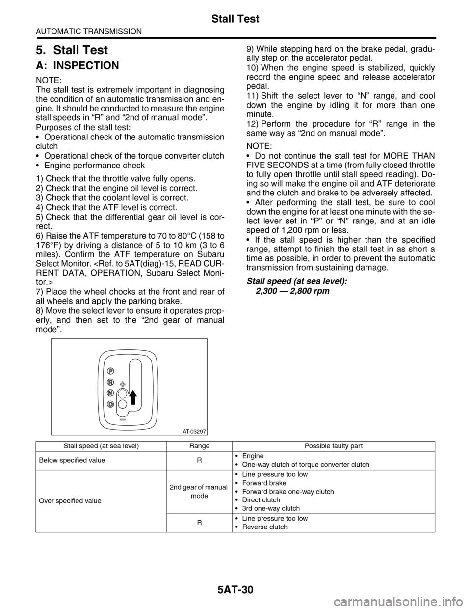
erly, and then set to the “2nd gear of manual
mode”.
9) While stepping hard on the brake pedal, gradu-
ally step on the accelerator pedal.
10) When the engine speed is stabilized, quickly
record the engine speed and release accelerator
pedal.
11) Shift the select lever to “N” range, and cool
down the engine by idling it for more than one
minute.
12) Perform the procedure for “R” range in the
same way as “2nd on manual mode”.
NOTE:
•Do not continue the stall test for MORE THAN
FIVE SECONDS at a time (from fully closed throttle
to fully open throttle until stall speed reading). Do-
ing so will make the engine oil and ATF deteriorate
and the clutch and brake to be adversely affected.
•After performing the stall test, be sure to cool
down the engine for at least one minute with the se-
lect lever set in “P” or “N” range, and at an idle
speed of 1,200 rpm or less.
•If the stall speed is higher than the specified
range, attempt to finish the stall test in as short a
time as possible, in order to prevent the automatic
transmission from sustaining damage.
Stall speed (at sea level):
2,300 — 2,800 rpm
AT-03297
Stall speed (at sea level) Range Possible faulty part
Below specified value R•Engine
•One-way clutch of torque converter clutch
Over specified value
2nd gear of manual
mode
•Line pressure too low
•Forward brake
•Forward brake one-way clutch
•Direct clutch
•3rd one-way clutch
R•Line pressure too low
•Reverse clutch
Page 2145 of 2453
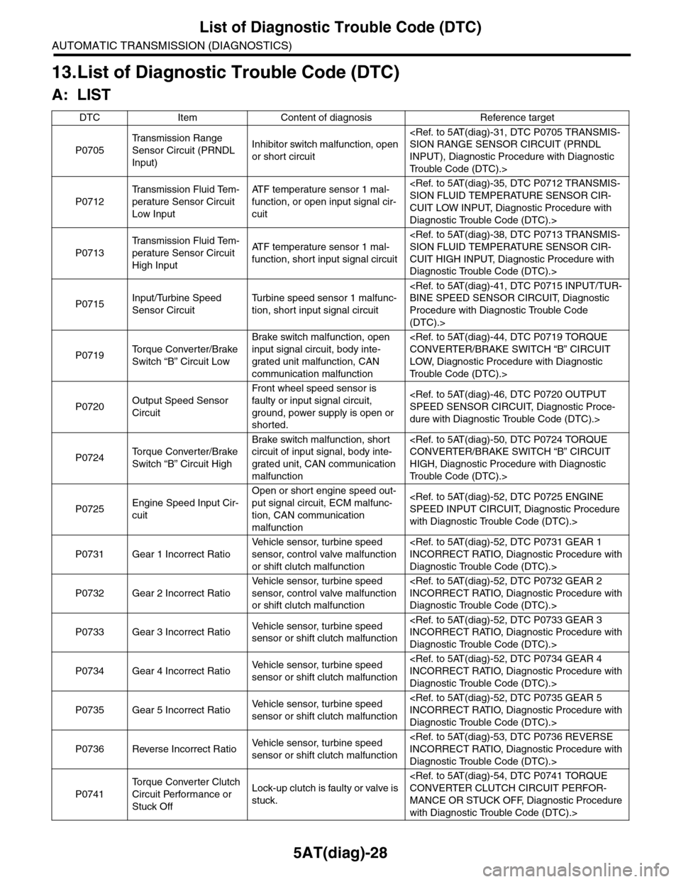
5AT(diag)-28
List of Diagnostic Trouble Code (DTC)
AUTOMATIC TRANSMISSION (DIAGNOSTICS)
13.List of Diagnostic Trouble Code (DTC)
A: LIST
DTC Item Content of diagnosis Reference target
P0705
Tr a n s m i s s i o n R a n g e
Sensor Circuit (PRNDL
Input)
Inhibitor switch malfunction, open
or short circuit
INPUT), Diagnostic Procedure with Diagnostic
Tr o u b l e C o d e ( D T C ) . >
P0712
Tr a n s m i s s i o n F l u i d Te m -
perature Sensor Circuit
Low Input
AT F t e m p e r a t u r e s e n s o r 1 m a l -
function, or open input signal cir-
cuit
CUIT LOW INPUT, Diagnostic Procedure with
Diagnostic Trouble Code (DTC).>
P0713
Tr a n s m i s s i o n F l u i d Te m -
perature Sensor Circuit
High Input
AT F t e m p e r a t u r e s e n s o r 1 m a l -
function, short input signal circuit
CUIT HIGH INPUT, Diagnostic Procedure with
Diagnostic Trouble Code (DTC).>
P0715Input/Turbine Speed
Sensor Circuit
Tu r b i n e s p e e d s e n s o r 1 m a l f u n c -
tion, short input signal circuit
Procedure with Diagnostic Trouble Code
(DTC).>
P0719To r q u e C o n v e r t e r / B r a k e
Switch “B” Circuit Low
Brake switch malfunction, open
input signal circuit, body inte-
grated unit malfunction, CAN
communication malfunction
LOW, Diagnostic Procedure with Diagnostic
Tr o u b l e C o d e ( D T C ) . >
P0720Output Speed Sensor
Circuit
Front wheel speed sensor is
faulty or input signal circuit,
ground, power supply is open or
shorted.
dure with Diagnostic Trouble Code (DTC).>
P0724To r q u e C o n v e r t e r / B r a k e
Switch “B” Circuit High
Brake switch malfunction, short
circuit of input signal, body inte-
grated unit, CAN communication
malfunction
HIGH, Diagnostic Procedure with Diagnostic
Tr o u b l e C o d e ( D T C ) . >
P0725Engine Speed Input Cir-
cuit
Open or short engine speed out-
put signal circuit, ECM malfunc-
tion, CAN communication
malfunction
with Diagnostic Trouble Code (DTC).>
P0731 Gear 1 Incorrect Ratio
Ve h i c l e s e n s o r, t u r b i n e s p e e d
sensor, control valve malfunction
or shift clutch malfunction
Diagnostic Trouble Code (DTC).>
P0732 Gear 2 Incorrect Ratio
Ve h i c l e s e n s o r, t u r b i n e s p e e d
sensor, control valve malfunction
or shift clutch malfunction
Diagnostic Trouble Code (DTC).>
P0733 Gear 3 Incorrect RatioVe h i c l e s e n s o r, t u r b i n e s p e e d
sensor or shift clutch malfunction
Diagnostic Trouble Code (DTC).>
P0734 Gear 4 Incorrect RatioVe h i c l e s e n s o r, t u r b i n e s p e e d
sensor or shift clutch malfunction
Diagnostic Trouble Code (DTC).>
P0735 Gear 5 Incorrect RatioVe h i c l e s e n s o r, t u r b i n e s p e e d
sensor or shift clutch malfunction
Diagnostic Trouble Code (DTC).>
P0736 Reverse Incorrect RatioVe h i c l e s e n s o r, t u r b i n e s p e e d
sensor or shift clutch malfunction
Diagnostic Trouble Code (DTC).>
P0741
To r q u e C o n v e r t e r C l u t c h
Circuit Performance or
Stuck Off
Lock-up clutch is faulty or valve is
stuck.
MANCE OR STUCK OFF, Diagnostic Procedure
with Diagnostic Trouble Code (DTC).>
Page 2147 of 2453
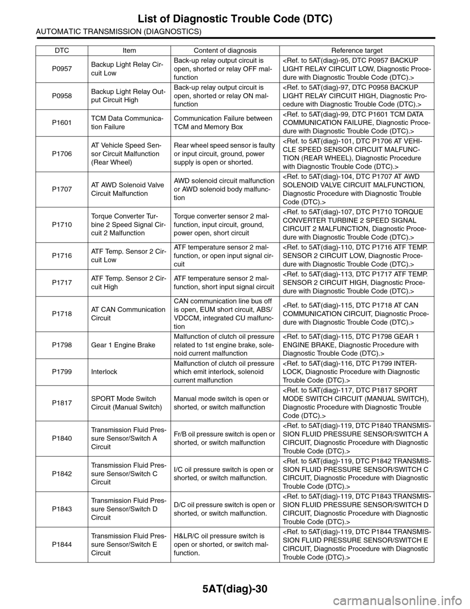
5AT(diag)-30
List of Diagnostic Trouble Code (DTC)
AUTOMATIC TRANSMISSION (DIAGNOSTICS)
P0957Backup Light Relay Cir-
cuit Low
Back-up relay output circuit is
open, shorted or relay OFF mal-
function
dure with Diagnostic Trouble Code (DTC).>
P0958Backup Light Relay Out-
put Circuit High
Back-up relay output circuit is
open, shorted or relay ON mal-
function
cedure with Diagnostic Trouble Code (DTC).>
P1601TCM Data Communica-
tion Failure
Communication Failure between
TCM and Memory Box
dure with Diagnostic Trouble Code (DTC).>
P1706
AT Ve h i c l e S p e e d S e n -
sor Circuit Malfunction
(Rear Wheel)
Rear wheel speed sensor is faulty
or input circuit, ground, power
supply is open or shorted.
TION (REAR WHEEL), Diagnostic Procedure
with Diagnostic Trouble Code (DTC).>
P1707AT A W D S o l e n o i d V a l v e
Circuit Malfunction
AWD solenoid circuit malfunction
or AWD solenoid body malfunc-
tion
Diagnostic Procedure with Diagnostic Trouble
Code (DTC).>
P1710
To r q u e C o n v e r t e r Tu r -
bine 2 Speed Signal Cir-
cuit 2 Malfunction
To r q u e c o n v e r t e r s e n s o r 2 m a l -
function, input circuit, ground,
power open, short circuit
CIRCUIT 2 MALFUNCTION, Diagnostic Proce-
dure with Diagnostic Trouble Code (DTC).>
P1716AT F Te m p . S e n s o r 2 C i r -
cuit Low
AT F t e m p e r a t u r e s e n s o r 2 m a l -
function, or open input signal cir-
cuit
dure with Diagnostic Trouble Code (DTC).>
P1717AT F Te m p . S e n s o r 2 C i r -
cuit High
AT F t e m p e r a t u r e s e n s o r 2 m a l -
function, short input signal circuit
dure with Diagnostic Trouble Code (DTC).>
P1718AT C A N C o m m u n i c a t i o n
Circuit
CAN communication line bus off
is open, EUM short circuit, ABS/
VDCCM, integrated CU malfunc-
tion
dure with Diagnostic Trouble Code (DTC).>
P1798 Gear 1 Engine Brake
Malfunction of clutch oil pressure
related to 1st engine brake, sole-
noid current malfunction
Diagnostic Trouble Code (DTC).>
P1799 Interlock
Malfunction of clutch oil pressure
which emit interlock, solenoid
current malfunction
Tr o u b l e C o d e ( D T C ) . >
P1817SPORT Mode Switch
Circuit (Manual Switch)
Manual mode switch is open or
shorted, or switch malfunction
Diagnostic Procedure with Diagnostic Trouble
Code (DTC).>
P1840
Tr a n s m i s s i o n F l u i d P r e s -
sure Sensor/Switch A
Circuit
Fr/B oil pressure switch is open or
shorted, or switch malfunction
CIRCUIT, Diagnostic Procedure with Diagnostic
Tr o u b l e C o d e ( D T C ) . >
P1842
Tr a n s m i s s i o n F l u i d P r e s -
sure Sensor/Switch C
Circuit
I/C oil pressure switch is open or
shorted, or switch malfunction.
CIRCUIT, Diagnostic Procedure with Diagnostic
Tr o u b l e C o d e ( D T C ) . >
P1843
Tr a n s m i s s i o n F l u i d P r e s -
sure Sensor/Switch D
Circuit
D/C oil pressure switch is open or
shorted, or switch malfunction.
CIRCUIT, Diagnostic Procedure with Diagnostic
Tr o u b l e C o d e ( D T C ) . >
P1844
Tr a n s m i s s i o n F l u i d P r e s -
sure Sensor/Switch E
Circuit
H&LR/C oil pressure switch is
open or shorted, or switch mal-
function.
CIRCUIT, Diagnostic Procedure with Diagnostic
Tr o u b l e C o d e ( D T C ) . >
DTC Item Content of diagnosis Reference target
Page 2170 of 2453
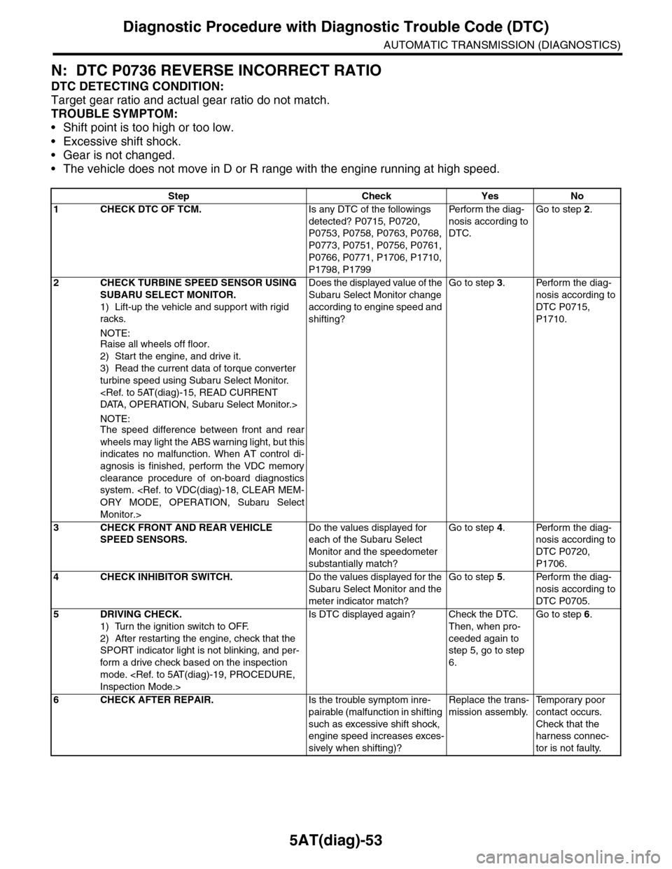
5AT(diag)-53
Diagnostic Procedure with Diagnostic Trouble Code (DTC)
AUTOMATIC TRANSMISSION (DIAGNOSTICS)
N: DTC P0736 REVERSE INCORRECT RATIO
DTC DETECTING CONDITION:
Target gear ratio and actual gear ratio do not match.
TROUBLE SYMPTOM:
•Shift point is too high or too low.
•Excessive shift shock.
•Gear is not changed.
•The vehicle does not move in D or R range with the engine running at high speed.
Step Check Yes No
1CHECK DTC OF TCM.Is any DTC of the followings
detected? P0715, P0720,
P0753, P0758, P0763, P0768,
P0773, P0751, P0756, P0761,
P0766, P0771, P1706, P1710,
P1798, P1799
Pe r for m t h e d ia g -
nosis according to
DTC.
Go to step 2.
2CHECK TURBINE SPEED SENSOR USING
SUBARU SELECT MONITOR.
1) Lift-up the vehicle and support with rigid
racks.
NOTE:Raise all wheels off floor.
2) Start the engine, and drive it.
3) Read the current data of torque converter
turbine speed using Subaru Select Monitor.
NOTE:The speed difference between front and rear
wheels may light the ABS warning light, but this
indicates no malfunction. When AT control di-
agnosis is finished, perform the VDC memory
clearance procedure of on-board diagnostics
system.
Monitor.>
Does the displayed value of the
Subaru Select Monitor change
according to engine speed and
shifting?
Go to step 3.Perform the diag-
nosis according to
DTC P0715,
P1710.
3CHECK FRONT AND REAR VEHICLE
SPEED SENSORS.
Do the values displayed for
each of the Subaru Select
Monitor and the speedometer
substantially match?
Go to step 4.Perform the diag-
nosis according to
DTC P0720,
P1706.
4CHECK INHIBITOR SWITCH.Do the values displayed for the
Subaru Select Monitor and the
meter indicator match?
Go to step 5.Perform the diag-
nosis according to
DTC P0705.
5DRIVING CHECK.
1) Turn the ignition switch to OFF.
2) After restarting the engine, check that the
SPORT indicator light is not blinking, and per-
form a drive check based on the inspection
mode.
Is DTC displayed again? Check the DTC.
Then, when pro-
ceeded again to
step 5, go to step
6.
Go to step 6.
6CHECK AFTER REPAIR.Is the trouble symptom inre-
pairable (malfunction in shifting
such as excessive shift shock,
engine speed increases exces-
sively when shifting)?
Replace the trans-
mission assembly.
Te m p o r a r y p o o r
contact occurs.
Check that the
harness connec-
tor is not faulty.
Page 2226 of 2453
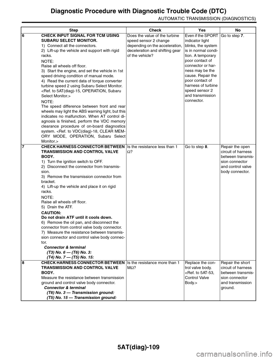
5AT(diag)-109
Diagnostic Procedure with Diagnostic Trouble Code (DTC)
AUTOMATIC TRANSMISSION (DIAGNOSTICS)
6CHECK INPUT SIGNAL FOR TCM USING
SUBARU SELECT MONITOR.
1) Connect all the connectors.
2) Lift-up the vehicle and support with rigid
racks.
NOTE:
Raise all wheels off floor.
3) Start the engine, and set the vehicle in 1st
speed driving condition of manual mode.
4) Read the current data of torque converter
turbine speed 2 using Subaru Select Monitor.
NOTE:The speed difference between front and rear
wheels may light the ABS warning light, but this
indicates no malfunction. When AT control di-
agnosis is finished, perform the VDC memory
clearance procedure of on-board diagnostics
system.
Monitor.>
Does the value of the turbine
speed sensor 2 change
depending on the acceleration,
deceleration and shifting gear
of the vehicle?
Even if the SPORT
indicator light
blinks, the system
is in normal condi-
tion. A temporary
poor contact of
connector or har-
ness may be the
cause. Repair the
poor contact of
harness of turbine
speed sensor 2
and transmission
connector.
Go to step 7.
7CHECK HARNESS CONNECTOR BETWEEN
TRANSMISSION AND CONTROL VALVE
BODY.
1) Turn the ignition switch to OFF.
2) Disconnect the connector from transmis-
sion.
3) Remove the transmission connector from
bracket.
4) Lift-up the vehicle and place it on rigid
racks.
NOTE:
Raise all wheels off floor.
5) Drain the ATF.
CAUTION:Do not drain ATF until it cools down.
6) Remove the oil pan, and disconnect the
connector from control valve body connector.
7) Measure the resistance between transmis-
sion connector and control valve body connec-
tor.
Connector & terminal
(T3) No. 6 — (T6) No. 3:
(T4) No. 7 — (T5) No. 15:
Is the resistance less than 1
Ω?
Go to step 8.Repair the open
circuit of harness
between transmis-
sion connector
and control valve
body connector.
8CHECK HARNESS CONNECTOR BETWEEN
TRANSMISSION AND CONTROL VALVE
BODY.
Measure the resistance between transmission
ground and control valve body connector.
Connector & terminal
(T6) No. 3 — Transmission ground:
(T5) No. 15 — Transmission ground:
Is the resistance more than 1
MΩ?
Replace the con-
trol valve body.
Body.>
Repair the short
circuit of harness
between transmis-
sion connector
and transmission
ground.
Step Check Yes No
Page 2313 of 2453

WI-29
Ground Circuit
WIRING SYSTEM
WI-08037
GND-08GND-08
(GLAY)B11
125678
131415169101112
34
17181920
BW A16
B12
T3
WB
5
YL
7
WR
YLWR
WWL
B18B16
B55B54A: B:TCM
B
B
B
W
REARWHEELSPEEDSENSOR
TORQUECONVERTERTURBINESENSOR 1
AT1
1
23
WLR
B11
T47
BW
WB
12345678
(BROWN)B12(GLAY)B:B55
123410 11 1219 20 21135614 1578916 17 1822 23 24
A:B54
12 7 8 9563410 11 1219 20 2113 14 15 16 17 1822 23 24
AT1
123
Page 2335 of 2453

WI-51
AT Control System
WIRING SYSTEM
WI-08057
A13
A23
A18
A24
A9
A17
A15
B7
A2
A11
A21
A12
B8
B12
B14
B3
B4
B20
B13
A16
B18
B17
A6
A22
B16A5
A14
A19
B21
B23
TCM
B22
TORQUE CONVERTER TURBINE SPEED SENSOR 1
REAR WHEEL SPEED SENSOR
CONTROL VALVE ASSY