wheel torque SUBARU TRIBECA 2009 1.G Service Owner's Guide
[x] Cancel search | Manufacturer: SUBARU, Model Year: 2009, Model line: TRIBECA, Model: SUBARU TRIBECA 2009 1.GPages: 2453, PDF Size: 46.32 MB
Page 875 of 2453
PB-4
Parking Brake Pedal
PARKING BRAKE
2. Parking Brake Pedal
A: REMOVAL
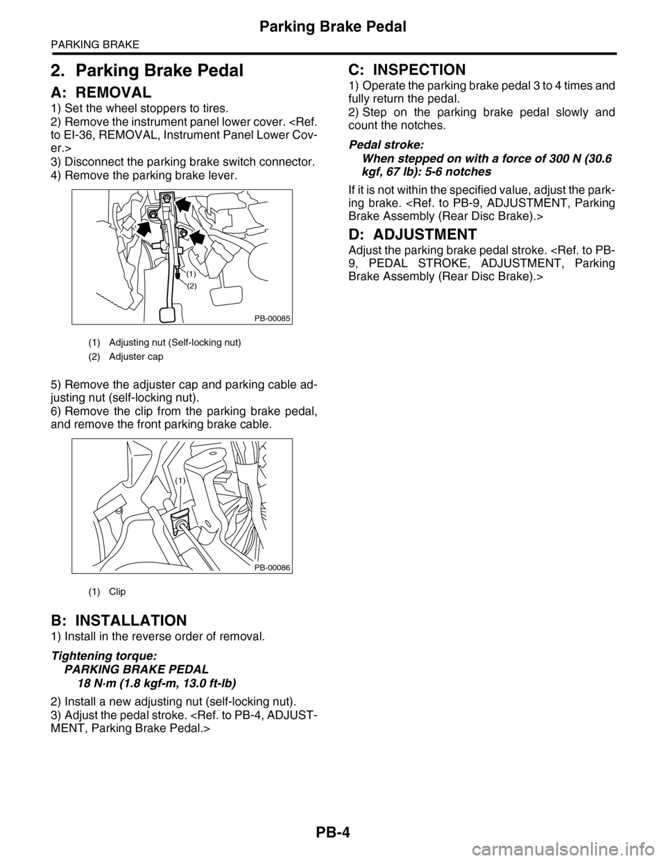
1) Set the wheel stoppers to tires.
2) Remove the instrument panel lower cover.
er.>
3) Disconnect the parking brake switch connector.
4) Remove the parking brake lever.
5) Remove the adjuster cap and parking cable ad-
justing nut (self-locking nut).
6) Remove the clip from the parking brake pedal,
and remove the front parking brake cable.
B: INSTALLATION
1) Install in the reverse order of removal.
Tightening torque:
PARKING BRAKE PEDAL
18 N·m (1.8 kgf-m, 13.0 ft-lb)
2) Install a new adjusting nut (self-locking nut).
3) Adjust the pedal stroke.
C: INSPECTION
1) Operate the parking brake pedal 3 to 4 times and
fully return the pedal.
2) Step on the parking brake pedal slowly and
count the notches.
Pedal stroke:
When stepped on with a force of 300 N (30.6
kgf, 67 lb): 5-6 notches
If it is not within the specified value, adjust the park-
ing brake.
D: ADJUSTMENT
Adjust the parking brake pedal stroke.
Brake Assembly (Rear Disc Brake).>
(1) Adjusting nut (Self-locking nut)
(2) Adjuster cap
(1) Clip
PB-00085
(1)
(2)
PB-00086
(1)
Page 877 of 2453
PB-6
Parking Brake Cable
PARKING BRAKE
5) Lift-up the vehicle, and then remove the rear
wheels.
6) Remove the rear parking brake cable from the
rear brake.
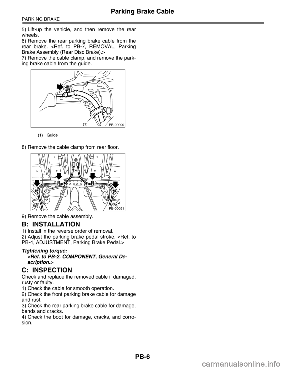
7) Remove the cable clamp, and remove the park-
ing brake cable from the guide.
8) Remove the cable clamp from rear floor.
9) Remove the cable assembly.
B: INSTALLATION
1) Install in the reverse order of removal.
2) Adjust the parking brake pedal stroke.
Tightening torque:
C: INSPECTION
Check and replace the removed cable if damaged,
rusty or faulty.
1) Check the cable for smooth operation.
2) Check the front parking brake cable for damage
and rust.
3) Check the rear parking brake cable for damage,
bends and cracks.
4) Check the boot for damage, cracks, and corro-
sion.
(1) Guide
PB-00090(1)
PB-00091
Page 883 of 2453
PS-3
General Description
POWER ASSISTED SYSTEM (POWER STEERING)
B: COMPONENT
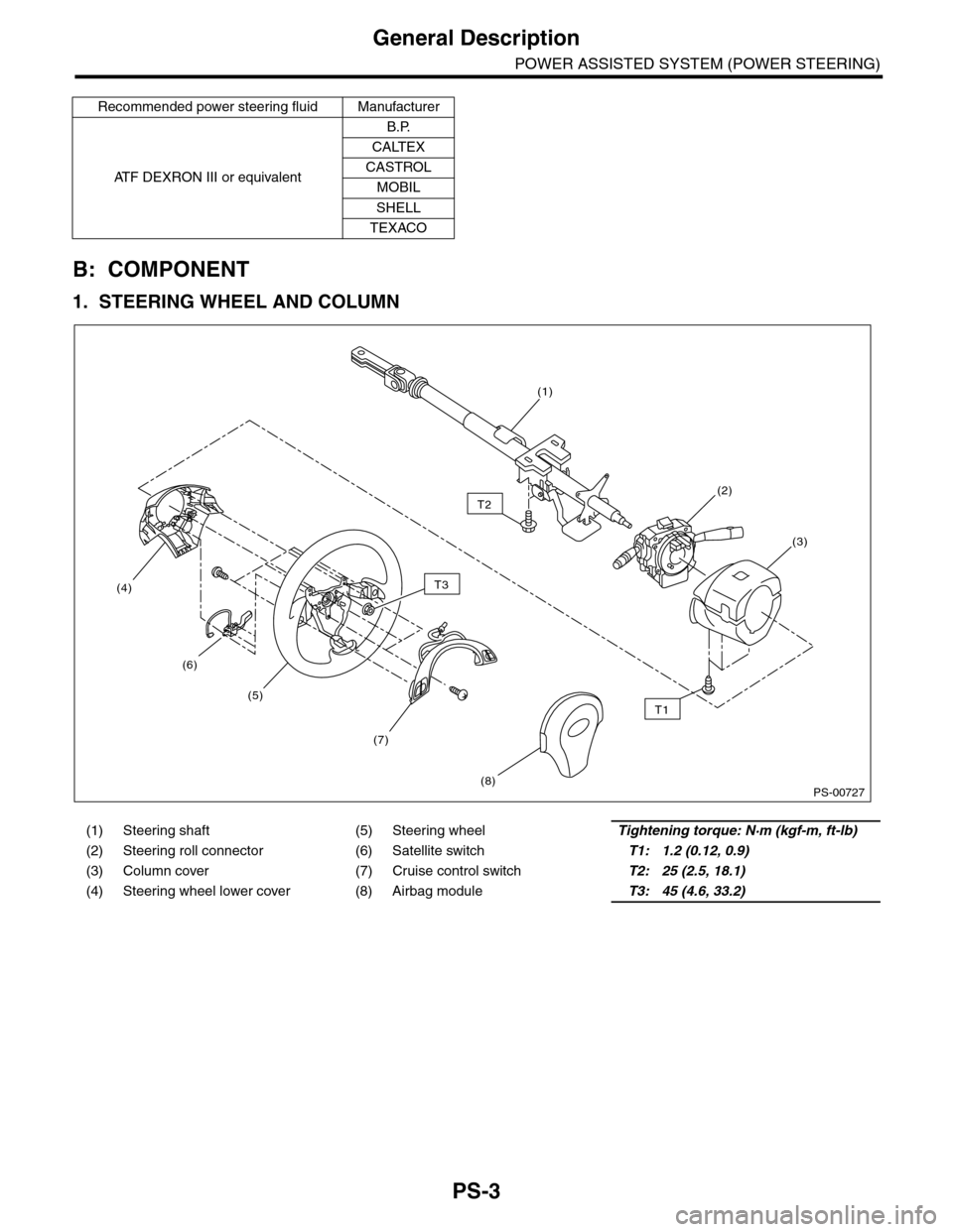
1. STEERING WHEEL AND COLUMN
Recommended power steering fluid Manufacturer
AT F D E X R O N I I I o r e q u i v a l e n t
B.P.
CALTEX
CASTROL
MOBIL
SHELL
TEXACO
(1) Steering shaft (5) Steering wheelTightening torque: N·m (kgf-m, ft-lb)
(2) Steering roll connector (6) Satellite switchT1: 1.2 (0.12, 0.9)
(3) Column cover (7) Cruise control switchT2: 25 (2.5, 18.1)
(4) Steering wheel lower cover (8) Airbag moduleT3: 45 (4.6, 33.2)
PS-00727
T2
T1
T3
(5)
(1)
(2)
(3)
(4)
(8)
(6)
(7)
Page 892 of 2453
PS-12
Steering Wheel
POWER ASSISTED SYSTEM (POWER STEERING)
2. Steering Wheel
A: REMOVAL
1) Disconnect the ground cable from the battery.
2) Set the tire to the straight–ahead position.
3) Remove the airbag module.
WARNING:
Always refer to “Air Bag System” before per-
forming service on the air bag modules.
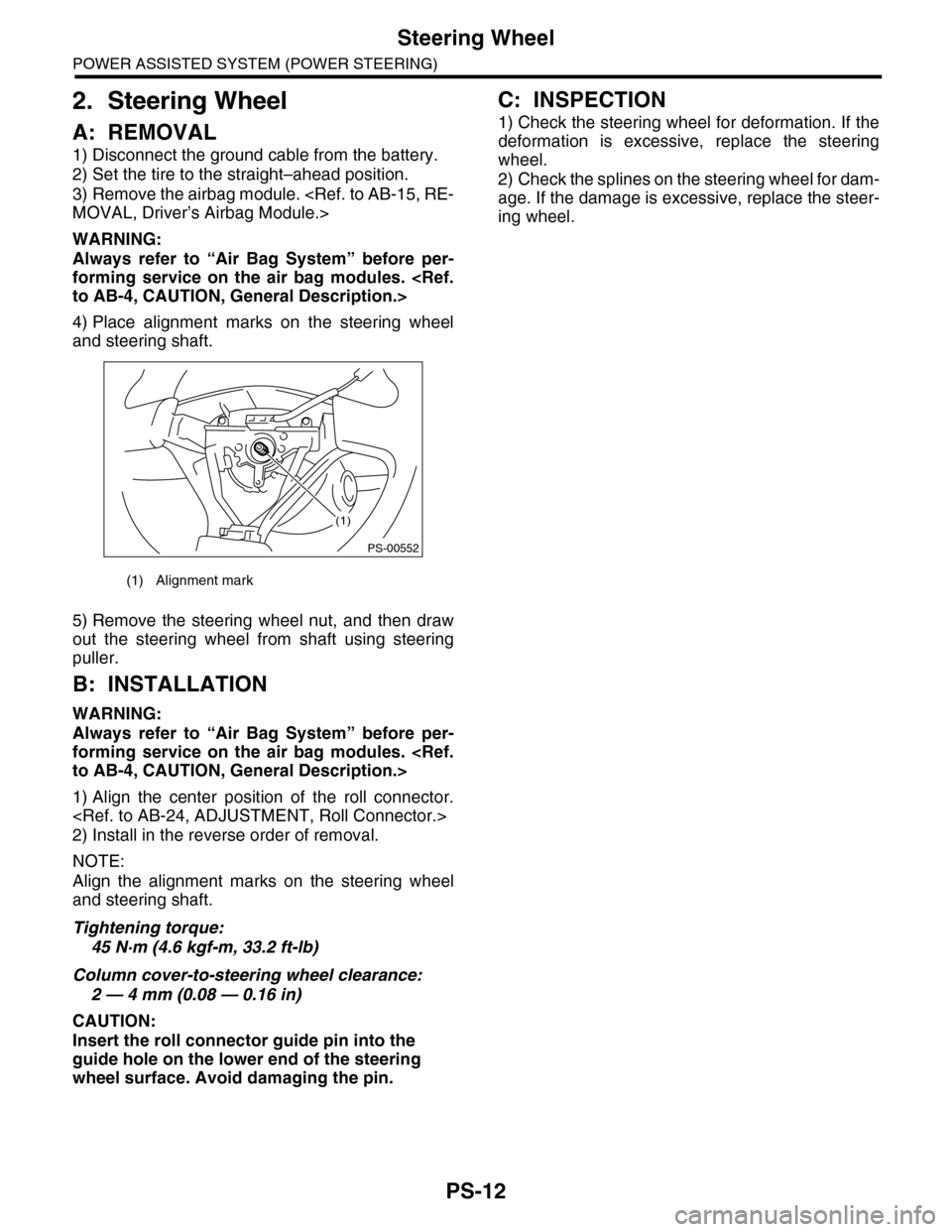
4) Place alignment marks on the steering wheel
and steering shaft.
5) Remove the steering wheel nut, and then draw
out the steering wheel from shaft using steering
puller.
B: INSTALLATION
WARNING:
Always refer to “Air Bag System” before per-
forming service on the air bag modules.
1) Align the center position of the roll connector.
2) Install in the reverse order of removal.
NOTE:
Align the alignment marks on the steering wheel
and steering shaft.
Tightening torque:
45 N·m (4.6 kgf-m, 33.2 ft-lb)
Column cover-to-steering wheel clearance:
2 — 4 mm (0.08 — 0.16 in)
CAUTION:
Insert the roll connector guide pin into the
guide hole on the lower end of the steering
wheel surface. Avoid damaging the pin.
C: INSPECTION
1) Check the steering wheel for deformation. If the
deformation is excessive, replace the steering
wheel.
2) Check the splines on the steering wheel for dam-
age. If the damage is excessive, replace the steer-
ing wheel.
(1) Alignment mark
(1)
PS-00552
Page 893 of 2453
PS-13
Universal Joint
POWER ASSISTED SYSTEM (POWER STEERING)
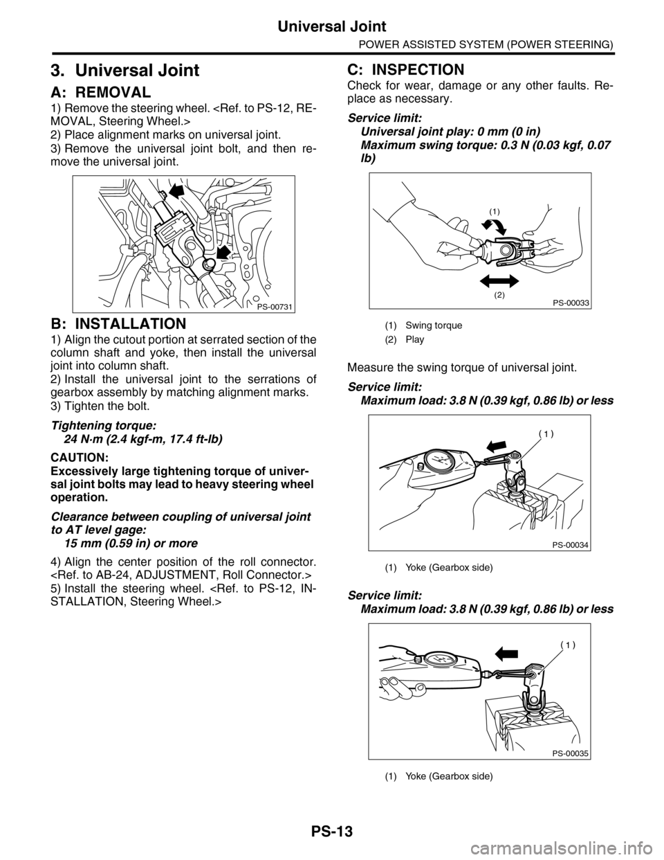
3. Universal Joint
A: REMOVAL
1) Remove the steering wheel.
2) Place alignment marks on universal joint.
3) Remove the universal joint bolt, and then re-
move the universal joint.
B: INSTALLATION
1) Align the cutout portion at serrated section of the
column shaft and yoke, then install the universal
joint into column shaft.
2) Install the universal joint to the serrations of
gearbox assembly by matching alignment marks.
3) Tighten the bolt.
Tightening torque:
24 N·m (2.4 kgf-m, 17.4 ft-lb)
CAUTION:
Excessively large tightening torque of univer-
sal joint bolts may lead to heavy steering wheel
operation.
Clearance between coupling of universal joint
to AT level gage:
15 mm (0.59 in) or more
4) Align the center position of the roll connector.
5) Install the steering wheel.
C: INSPECTION
Check for wear, damage or any other faults. Re-
place as necessary.
Service limit:
Universal joint play: 0 mm (0 in)
Maximum swing torque: 0.3 N (0.03 kgf, 0.07
lb)
Measure the swing torque of universal joint.
Service limit:
Maximum load: 3.8 N (0.39 kgf, 0.86 lb) or less
Service limit:
Maximum load: 3.8 N (0.39 kgf, 0.86 lb) or less
PS-00731
(1) Swing torque
(2) Play
(1) Yoke (Gearbox side)
(1) Yoke (Gearbox side)
PS-00033
(1)
(2)
PS-00034
PS-00035
Page 896 of 2453
PS-16
Tilt Steering Column
POWER ASSISTED SYSTEM (POWER STEERING)
B: INSTALLATION
1) Insert the end of the steering shaft into the toe
board.
2) With the tilt lever secured, tighten the steering
shaft mounting bolts under instrument panel.
Tightening torque:
25 N·m (2.5 kgf-m, 18.1 ft-lb)
3) Connect all the connectors under the instrument
panel.
4) Connect the airbag system connector at the har-
ness spool.
NOTE:
Make sure to apply double lock.
5) Install the instrument panel lower cover with tilt
lever held in the lowered position.
6) Install the universal joint.
7) Align the center position of the roll connector.
8) Install the steering wheel.
CAUTION:
Insert the roll connector guide pin into the
guide hole on lower end of steering wheel sur-
face to prevent damage.
C: DISASSEMBLY
Remove the two screws securing the upper steer-
ing column covers, and the two screws securing
the combination switch, and then remove related
parts.
D: ASSEMBLY
Insert the combination switch to the upper column
shaft, and install the upper column cover. Then
route the ignition key harness and combination
switch harness between the column cover mount-
ing bosses.
Tightening torque:
1.2 N·m (0.12 kgf-m, 0.9 ft-lb)
CAUTION:
Do not overtorque the screw.
E: INSPECTION
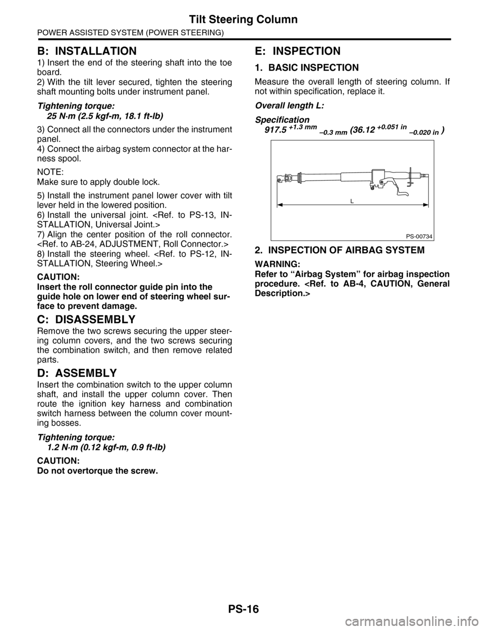
1. BASIC INSPECTION
Measure the overall length of steering column. If
not within specification, replace it.
Overall length L:
Specification
917.5 +1.3 mm –0.3 mm (36.12 +0.051 in –0.020 in )
2. INSPECTION OF AIRBAG SYSTEM
WARNING:
Refer to “Airbag System” for airbag inspection
procedure.
PS-00734
L
Page 899 of 2453
PS-19
Steering Gearbox
POWER ASSISTED SYSTEM (POWER STEERING)
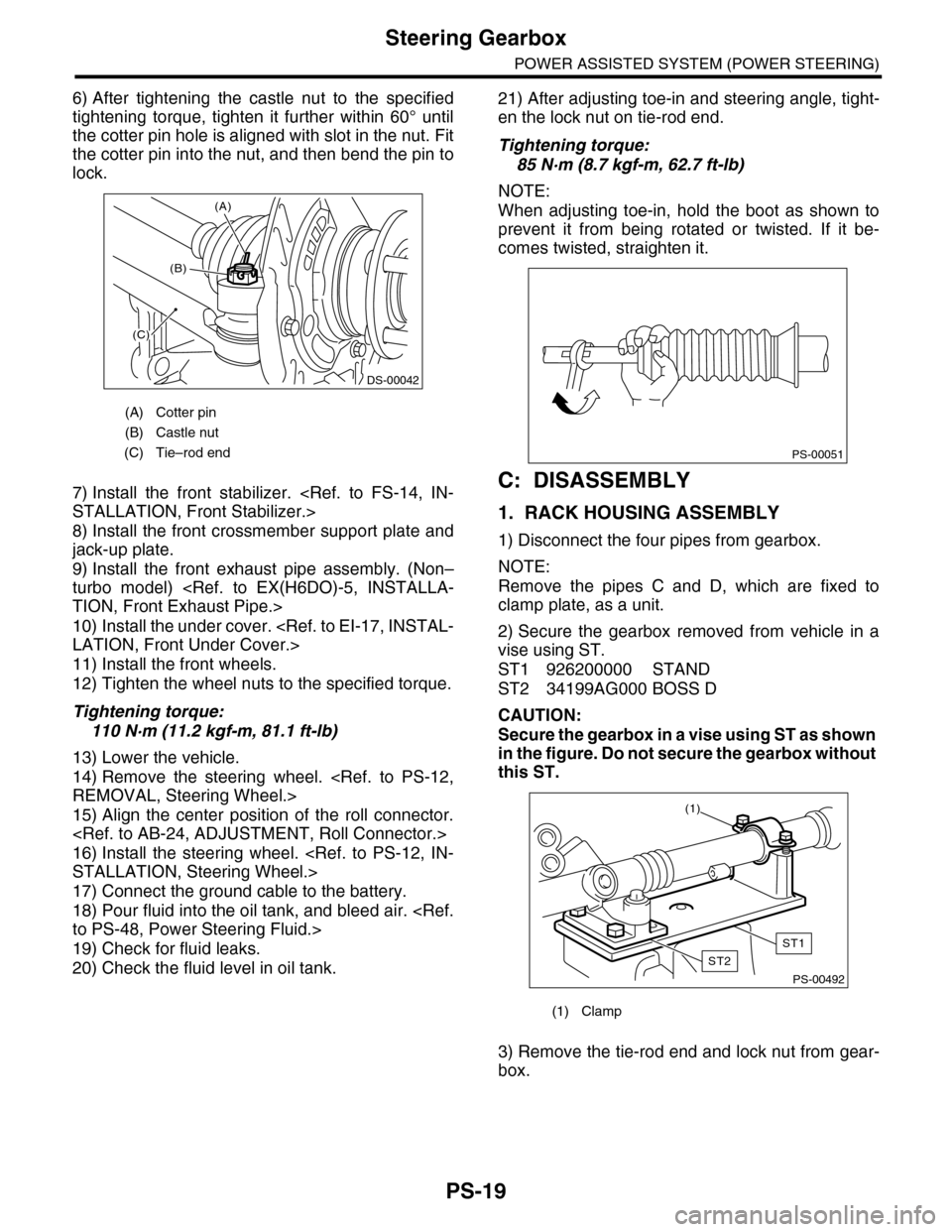
6) After tightening the castle nut to the specified
tightening torque, tighten it further within 60° until
the cotter pin hole is aligned with slot in the nut. Fit
the cotter pin into the nut, and then bend the pin to
lock.
7) Install the front stabilizer.
8) Install the front crossmember support plate and
jack-up plate.
9) Install the front exhaust pipe assembly. (Non–
turbo model)
10) Install the under cover.
11) Install the front wheels.
12) Tighten the wheel nuts to the specified torque.
Tightening torque:
110 N·m (11.2 kgf-m, 81.1 ft-lb)
13) Lower the vehicle.
14) Remove the steering wheel.
15) Align the center position of the roll connector.
16) Install the steering wheel.
17) Connect the ground cable to the battery.
18) Pour fluid into the oil tank, and bleed air.
19) Check for fluid leaks.
20) Check the fluid level in oil tank.
21) After adjusting toe-in and steering angle, tight-
en the lock nut on tie-rod end.
Tightening torque:
85 N·m (8.7 kgf-m, 62.7 ft-lb)
NOTE:
When adjusting toe-in, hold the boot as shown to
prevent it from being rotated or twisted. If it be-
comes twisted, straighten it.
C: DISASSEMBLY
1. RACK HOUSING ASSEMBLY
1) Disconnect the four pipes from gearbox.
NOTE:
Remove the pipes C and D, which are fixed to
clamp plate, as a unit.
2) Secure the gearbox removed from vehicle in a
vise using ST.
ST1 926200000 STAND
ST2 34199AG000 BOSS D
CAUTION:
Secure the gearbox in a vise using ST as shown
in the figure. Do not secure the gearbox without
this ST.
3) Remove the tie-rod end and lock nut from gear-
box.
(A) Cotter pin
(B) Castle nut
(C) Tie–rod end
DS-00042
(C)
(B)
(A)
(1) Clamp
PS-00051
PS-00492
(1)
ST1
ST2
Page 932 of 2453
PS-52
General Diagnostic Table
POWER ASSISTED SYSTEM (POWER STEERING)
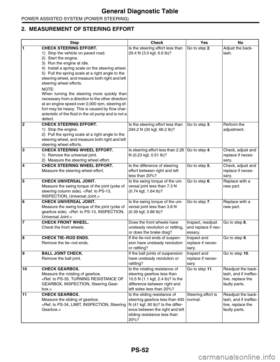
2. MEASUREMENT OF STEERING EFFORT
Step Check Yes No
1CHECK STEERING EFFORT.
1) Stop the vehicle on paved road.
2) Start the engine.
3) Run the engine at idle.
4) Install a spring scale on the steering wheel.
5) Pull the spring scale at a right angle to the
steering wheel, and measure both right and left
steering wheel efforts.
NOTE:When turning the steering more quickly than
necessary from a direction to the other direction
at an engine speed over 2,000 rpm, steering ef-
fort may be heavy. This is caused by flow char-
acteristic of the fluid in the oil pump and is not a
defect.
Is the steering effort less than
29.4 N (3.0 kgf, 6.6 lb)?
Go to step 2.Adjust the back-
lash.
2CHECK STEERING EFFORT.
1) Stop the engine.
2) Pull the spring scale at a right angle to the
steering wheel, and measure both right and left
steering wheel efforts.
Is the steering effort less than
294.2 N (30 kgf, 66.2 lb)?
Go to step 3.Perform the
adjustment.
3CHECK STEERING WHEEL EFFORT.
1) Remove the universal joint.
2) Measure the steering wheel effort.
Is steering effort less than 2.26
N (0.23 kgf, 0.51 lb)?
Go to step 4.Check, adjust and
replace if neces-
sary.
4CHECK STEERING WHEEL EFFORT.
Measure the steering wheel effort.
Is the difference of steering
effort between right and left
less than 20%?
Go to step 5.Check, adjust and
replace if neces-
sary.
5CHECK UNIVERSAL JOINT.
Measure the swing torque of the joint (yoke of
steering column side).
Is the swing torque of the uni-
versal joint less than 7.3 N
(0.74 kgf, 1.64 lb)?
Go to step 6.Replace with a
new part.
6CHECK UNIVERSAL JOINT.
Measure the swing torque of the joint (yoke of
gearbox side).
Is the swing torque of the uni-
versal joint less than 3.8 N
(0.39 kgf, 0.86 lb)?
Go to step 7.Replace with a
new part.
7CHECK FRONT WHEEL.
Check the front wheels.
Does the front wheels have
unsteady revolution or rattling,
or does the brake drag?
Inspect, readjust
and replace if nec-
essary.
Go to step 8.
8CHECK TIE–ROD ENDS.
Remove the tie–rod ends.
If the tie-rod ends of suspen-
sion have unsteady revolution
or rattling?
Inspect and
replace if neces-
sary.
Go to step 9.
9BALL JOINT CHECK.
Remove the ball joint.
If the ball joints of suspension
have unsteady revolution or
rattling?
Inspect and
replace if neces-
sary.
Go to step 10.
10 CHECK GEARBOX.
Measure the rotating of gearbox.
box.>
Is the rotating resistance of
steering gearbox less than
10.5 N (1.1 kgf, 2.4 lb)? Is the
difference between right and
left sides less than 20%?
Go to step 11.Readjust the back-
lash, and if ineffec-
tive, replace the
faulty par ts.
11 CHECK GEARBOX.
Measure the sliding of gearbox.
Is the sliding resistance of
steering gearbox less than 400
N (41 kgf, 90 lb)? Is the differ-
ence between the right and left
sliding resistance less than
20%?
Steering effort is
normal.
Readjust the back-
lash, and if ineffec-
tive, replace the
faulty par ts.
Page 941 of 2453

RS-8
Rear Stabilizer
REAR SUSPENSION
3. Rear Stabilizer
A: REMOVAL
1) Lift-up the vehicle, and then remove the rear
wheels.
2) Remove the stabilizer link.
3) Remove the stabilizer link.
B: INSTALLATION
NOTE:
•Use a new flange nut (with WAX).
•Always tighten the stabilizer bushing in the state
where the vehicle is at curb weight and the wheels
are in full contact with the ground.
Install in the reverse order of removal.
Tightening torque:
Stabilizer link
60 N·m (6.1 kgf-m, 44 ft-lb)
Stabilizer clamp
35 N·m (3.6 kgf-m, 25.8 ft-lb)
C: INSPECTION
1) Check the bushing for cracks, fatigue or dam-
age.
2) Check the stabilizer link for damage.
RS-00178
RS-00179
Page 942 of 2453
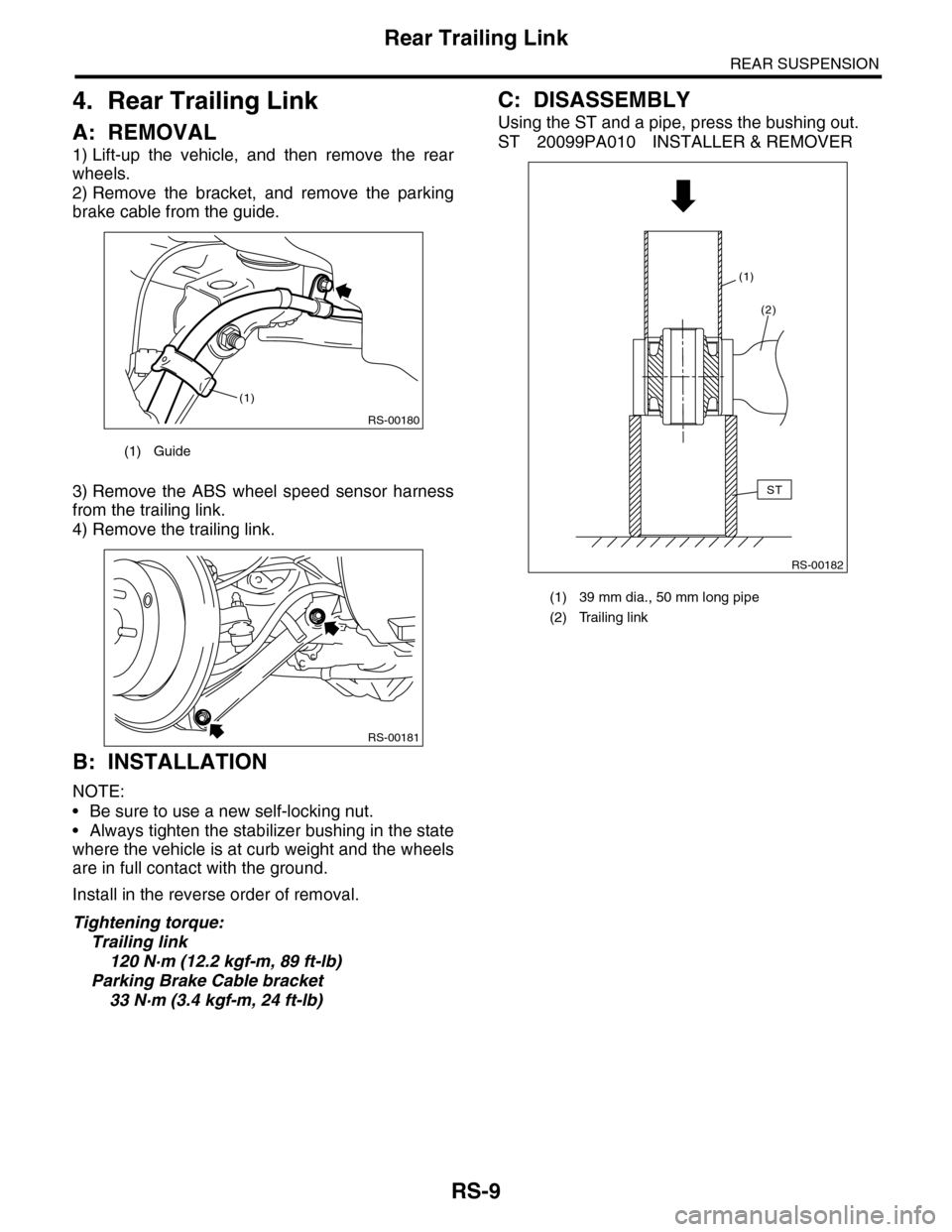
RS-9
Rear Trailing Link
REAR SUSPENSION
4. Rear Trailing Link
A: REMOVAL
1) Lift-up the vehicle, and then remove the rear
wheels.
2) Remove the bracket, and remove the parking
brake cable from the guide.
3) Remove the ABS wheel speed sensor harness
from the trailing link.
4) Remove the trailing link.
B: INSTALLATION
NOTE:
•Be sure to use a new self-locking nut.
•Always tighten the stabilizer bushing in the state
where the vehicle is at curb weight and the wheels
are in full contact with the ground.
Install in the reverse order of removal.
Tightening torque:
Trailing link
120 N·m (12.2 kgf-m, 89 ft-lb)
Parking Brake Cable bracket
33 N·m (3.4 kgf-m, 24 ft-lb)
C: DISASSEMBLY
Using the ST and a pipe, press the bushing out.
ST 20099PA010 INSTALLER & REMOVER
(1) Guide
RS-00180
(1)
RS-00181
(1) 39 mm dia., 50 mm long pipe
(2) Trailing link
RS-00182
ST
(2)
(1)