SUBARU TRIBECA 2009 1.G Service Workshop Manual
TRIBECA 2009 1.G
SUBARU
SUBARU
https://www.carmanualsonline.info/img/17/7322/w960_7322-0.png
SUBARU TRIBECA 2009 1.G Service Workshop Manual
Trending: power steering fluid, Rear differential, heating engine, B135 - 30, steering wheel adjustment, ECO mode, Variable
Page 451 of 2453
IDI-12
Combination Meter
INSTRUMENTATION/DRIVER INFO
C: DISASSEMBLY
CAUTION:
•Use gloves to avoid damage and getting fingerprints on the glass surface and meter surfaces.
•Be careful not to apply excessive force to the trip knob.
•Be sure not to touch the meter indicator needle.
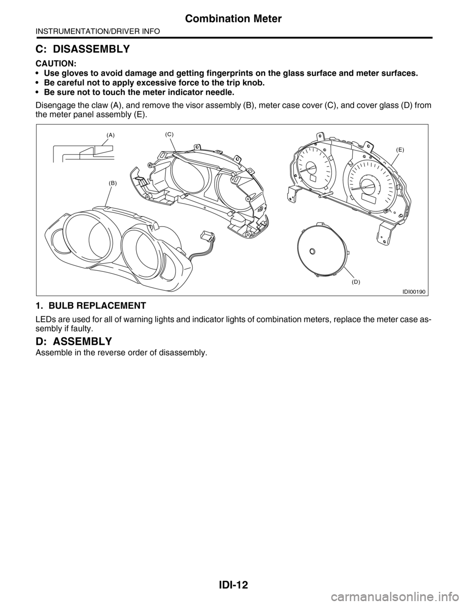
Disengage the claw (A), and remove the visor assembly (B), meter case cover (C), and cover glass (D) from
the meter panel assembly (E).
1. BULB REPLACEMENT
LEDs are used for all of warning lights and indicator lights of combination meters, replace the meter case as-
sembly if faulty.
D: ASSEMBLY
Assemble in the reverse order of disassembly.
IDI00190
(A)
(B)
(C)
(D)
(E)
Page 452 of 2453
IDI-13
Speedometer
INSTRUMENTATION/DRIVER INFO
4. Speedometer
A: SPECIFICATION
Since the meter case assembly cannot be disas-
sembled, do not remove or inspect the speedome-
ter alone. (Do not remove the cover on the back
side.)
Page 453 of 2453
IDI-14
Tachometer
INSTRUMENTATION/DRIVER INFO
5. Tachometer
A: SPECIFICATION
Since the meter case assembly cannot be disas-
sembled, do not remove or inspect the tachometer
alone. (Do not remove the cover on the back side.)
Page 454 of 2453
IDI-15
Fuel Gauge
INSTRUMENTATION/DRIVER INFO
6. Fuel Gauge
A: SPECIFICATION
Since the meter case assembly cannot be disas-
sembled, do not remove or inspect the fuel gauge
as alone. (Do not remove the cover on the back
side.)
Page 455 of 2453
IDI-16
Engine Coolant Temperature Gauge
INSTRUMENTATION/DRIVER INFO
7. Engine Coolant Temperature
Gauge
A: SPECIFICATION
Since the meter case assembly cannot be disas-
sembled, do not remove or inspect the temperature
gauge alone. (Do not remove the cover on the back
side.)
Page 456 of 2453
IDI-17
Warning Box
INSTRUMENTATION/DRIVER INFO
8. Warning Box
A: REMOVAL
1) Disconnect the ground cable from battery.
2) Remove the upper grille.
MOVAL, Air Vent Grille.>
3) Remove the screws of warning box (1) and pull
out the warning box.
4) Disconnect the connector in the rear side of
warning box to remove the warning box.
B: INSTALLATION
Install in the reverse order of removal.
CAUTION:
•Make sure the electrical connector is con-
nected securely.
•Make sure that each indicator operates nor-
mally.
IDI00191
(1)
Page 457 of 2453
IDI-18
Warning Box
INSTRUMENTATION/DRIVER INFO
Page 458 of 2453
LAN(diag)-2
Basic Diagnostic Procedure
LAN SYSTEM (DIAGNOSTICS)
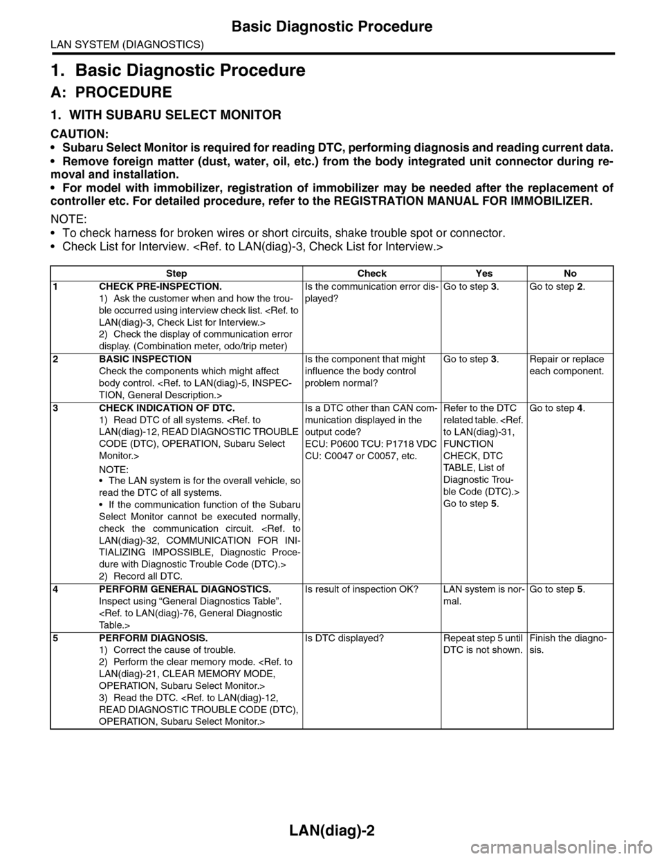
1. Basic Diagnostic Procedure
A: PROCEDURE
1. WITH SUBARU SELECT MONITOR
CAUTION:
•Subaru Select Monitor is required for reading DTC, performing diagnosis and reading current data.
•Remove foreign matter (dust, water, oil, etc.) from the body integrated unit connector during re-
moval and installation.
•For model with immobilizer, registration of immobilizer may be needed after the replacement of
controller etc. For detailed procedure, refer to the REGISTRATION MANUAL FOR IMMOBILIZER.
NOTE:
•To check harness for broken wires or short circuits, shake trouble spot or connector.
•Check List for Interview.
Step Check Yes No
1CHECK PRE-INSPECTION.
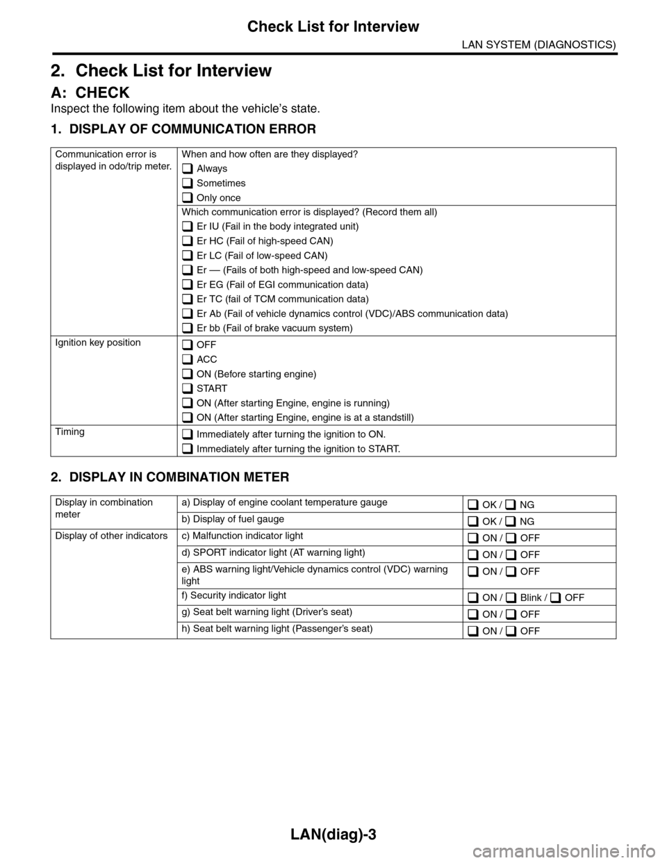
1) Ask the customer when and how the trou-
ble occurred using interview check list.
LAN(diag)-3, Check List for Interview.>
2) Check the display of communication error
display. (Combination meter, odo/trip meter)
Is the communication error dis-
played?
Go to step 3.Go to step 2.
2BASIC INSPECTION
Check the components which might affect
body control.
TION, General Description.>
Is the component that might
influence the body control
problem normal?
Go to step 3.Repair or replace
each component.
3CHECK INDICATION OF DTC.
1) Read DTC of all systems.
LAN(diag)-12, READ DIAGNOSTIC TROUBLE
CODE (DTC), OPERATION, Subaru Select
Monitor.>
NOTE:•The LAN system is for the overall vehicle, so
read the DTC of all systems.
•If the communication function of the Subaru
Select Monitor cannot be executed normally,
check the communication circuit.
LAN(diag)-32, COMMUNICATION FOR INI-
TIALIZING IMPOSSIBLE, Diagnostic Proce-
dure with Diagnostic Trouble Code (DTC).>
2) Record all DTC.
Is a DTC other than CAN com-
munication displayed in the
output code?
ECU: P0600 TCU: P1718 VDC
CU: C0047 or C0057, etc.
Refer to the DTC
related table.
to LAN(diag)-31,
FUNCTION
CHECK, DTC
TA B L E , L i s t o f
Diagnostic Trou-
ble Code (DTC).>
Go to step 5.
Go to step 4.
4PERFORM GENERAL DIAGNOSTICS.
Inspect using “General Diagnostics Table”.
Ta b l e . >
Is result of inspection OK? LAN system is nor-
mal.
Go to step 5.
5PERFORM DIAGNOSIS.
1) Correct the cause of trouble.
2) Perform the clear memory mode.
LAN(diag)-21, CLEAR MEMORY MODE,
OPERATION, Subaru Select Monitor.>
3) Read the DTC.
READ DIAGNOSTIC TROUBLE CODE (DTC),
OPERATION, Subaru Select Monitor.>
Is DTC displayed? Repeat step 5 until
DTC is not shown.
Finish the diagno-
sis.
Page 459 of 2453
LAN(diag)-3
Check List for Interview
LAN SYSTEM (DIAGNOSTICS)
2. Check List for Interview
A: CHECK
Inspect the following item about the vehicle’s state.
1. DISPLAY OF COMMUNICATION ERROR
2. DISPLAY IN COMBINATION METER
Communication error is
displayed in odo/trip meter.
When and how often are they displayed?
Always
Sometimes
Only once
Which communication error is displayed? (Record them all)
Er IU (Fail in the body integrated unit)
Er HC (Fail of high-speed CAN)
Er LC (Fail of low-speed CAN)
Er –– (Fails of both high-speed and low-speed CAN)
Er EG (Fail of EGI communication data)
Er TC (fail of TCM communication data)
Er Ab (Fail of vehicle dynamics control (VDC)/ABS communication data)
Er bb (Fail of brake vacuum system)
Ignition key position OFF
ACC
ON (Before starting engine)
START
ON (After starting Engine, engine is running)
ON (After starting Engine, engine is at a standstill)
Timing Immediately after turning the ignition to ON.
Immediately after turning the ignition to START.
Display in combination
meter
a) Display of engine coolant temperature gauge OK / NG
b) Display of fuel gauge OK / NG
Display of other indicators c) Malfunction indicator light ON / OFF
d) SPORT indicator light (AT warning light) ON / OFF
e) ABS warning light/Vehicle dynamics control (VDC) warning
light ON / OFF
f) Security indicator light ON / Blink / OFF
g) Seat belt warning light (Driver’s seat) ON / OFF
h) Seat belt warning light (Passenger’s seat) ON / OFF
Page 460 of 2453
LAN(diag)-4
Check List for Interview
LAN SYSTEM (DIAGNOSTICS)
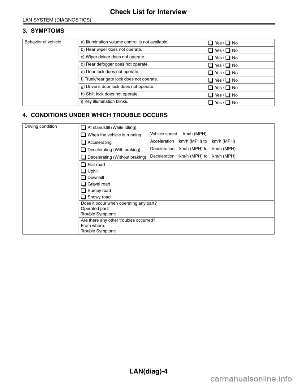
3. SYMPTOMS
4. CONDITIONS UNDER WHICH TROUBLE OCCURS
Behavior of vehicle a) Illumination volume control is not available. Yes / No
b) Rear wiper does not operate. Yes / No
c) Wiper deicer does not operate. Yes / No
d) Rear defogger does not operate. Yes / No
e) Door lock does not operate. Yes / No
f) Trunk/rear gate lock does not operate. Yes / No
g) Driver’s door lock does not operate. Yes / No
h) Shift lock does not operate. Yes / No
i) Key illumination blinks. Yes / No
Driving condition At standstill (While idling)
When the vehicle is runningVe h i c l e s p e e d k m / h ( M P H )
AcceleratingAcceleration km/h (MPH) to km/h (MPH)
Decelerating (With braking)Deceleration km/h (MPH) to km/h (MPH)
Decelerating (Without braking)Deceleration km/h (MPH) to km/h (MPH)
Flat road
Uphill
Downhill
Gravel road
Bumpy road
Snowy road
Does it occur when operating any part?
Operated part:
Tr o u b l e S y m p t o m :
Are there any other troubles occurred?
Fr o m wh er e :
Tr o u b l e S y m p t o m :
Trending: width, fuel, navi, Heat, immobilizer, turn signal, brake pads
