SUZUKI GRAND VITARA 1999 2.G Owners Manual
Manufacturer: SUZUKI, Model Year: 1999, Model line: GRAND VITARA, Model: SUZUKI GRAND VITARA 1999 2.GPages: 656, PDF Size: 14.31 MB
Page 111 of 656
![SUZUKI GRAND VITARA 1999 2.G Owners Manual 5A-4 BRAKES PIPE/HOSE/MASTER CYLINDER
For RH steering vehicle
[D]: View D 1. E-ring
[a]: Clamp a 2. Flexible hose
[b]: Clamp b 3. Hose washer
[c]: Clamp d 4. Hose bolt
T: Top side 5. Brake caliper
F: SUZUKI GRAND VITARA 1999 2.G Owners Manual 5A-4 BRAKES PIPE/HOSE/MASTER CYLINDER
For RH steering vehicle
[D]: View D 1. E-ring
[a]: Clamp a 2. Flexible hose
[b]: Clamp b 3. Hose washer
[c]: Clamp d 4. Hose bolt
T: Top side 5. Brake caliper
F:](/img/20/7583/w960_7583-110.png)
5A-4 BRAKES PIPE/HOSE/MASTER CYLINDER
For RH steering vehicle
[D]: View D 1. E-ring
[a]: Clamp a 2. Flexible hose
[b]: Clamp b 3. Hose washer
[c]: Clamp d 4. Hose bolt
T: Top side 5. Brake caliper
F: Front side 6. 2 way joint
Page 112 of 656
![SUZUKI GRAND VITARA 1999 2.G Owners Manual BRAKES PIPE/HOSE/MASTER CYLINDER 5A-5
For LH steering vehicle
[D]: View D 1. E-ring
[a]: Clamp a 2. Flexible hose
[b]: Clamp b 3. Hose washer
[d]: Clamp d 4. Hose bolt
T: Top side 5. Brake caliper
F: SUZUKI GRAND VITARA 1999 2.G Owners Manual BRAKES PIPE/HOSE/MASTER CYLINDER 5A-5
For LH steering vehicle
[D]: View D 1. E-ring
[a]: Clamp a 2. Flexible hose
[b]: Clamp b 3. Hose washer
[d]: Clamp d 4. Hose bolt
T: Top side 5. Brake caliper
F:](/img/20/7583/w960_7583-111.png)
BRAKES PIPE/HOSE/MASTER CYLINDER 5A-5
For LH steering vehicle
[D]: View D 1. E-ring
[a]: Clamp a 2. Flexible hose
[b]: Clamp b 3. Hose washer
[d]: Clamp d 4. Hose bolt
T: Top side 5. Brake caliper
F: Front side 6. 2 way joint
Page 113 of 656
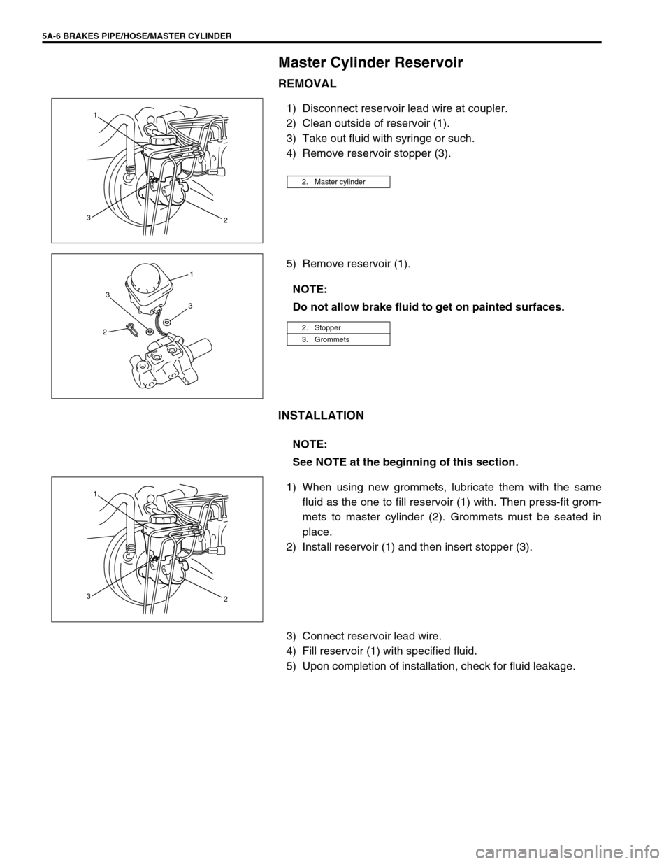
5A-6 BRAKES PIPE/HOSE/MASTER CYLINDER
Master Cylinder Reservoir
REMOVAL
1) Disconnect reservoir lead wire at coupler.
2) Clean outside of reservoir (1).
3) Take out fluid with syringe or such.
4) Remove reservoir stopper (3).
5) Remove reservoir (1).
INSTALLATION
1) When using new grommets, lubricate them with the same
fluid as the one to fill reservoir (1) with. Then press-fit grom-
mets to master cylinder (2). Grommets must be seated in
place.
2) Install reservoir (1) and then insert stopper (3).
3) Connect reservoir lead wire.
4) Fill reservoir (1) with specified fluid.
5) Upon completion of installation, check for fluid leakage.
2. Master cylinder
1
3
2
NOTE:
Do not allow brake fluid to get on painted surfaces.
2. Stopper
3. Grommets
3
31
2
NOTE:
See NOTE at the beginning of this section.
1
3
2
Page 114 of 656
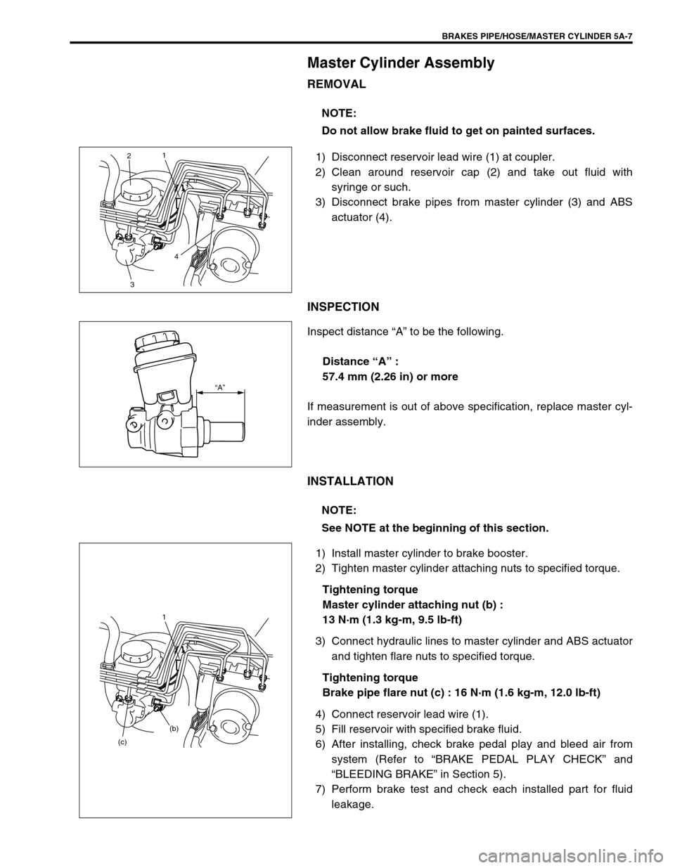
BRAKES PIPE/HOSE/MASTER CYLINDER 5A-7
Master Cylinder Assembly
REMOVAL
1) Disconnect reservoir lead wire (1) at coupler.
2) Clean around reservoir cap (2) and take out fluid with
syringe or such.
3) Disconnect brake pipes from master cylinder (3) and ABS
actuator (4).
INSPECTION
Inspect distance “A” to be the following.
Distance “A” :
57.4 mm (2.26 in) or more
If measurement is out of above specification, replace master cyl-
inder assembly.
INSTALLATION
1) Install master cylinder to brake booster.
2) Tighten master cylinder attaching nuts to specified torque.
Tightening torque
Master cylinder attaching nut (b) :
13 N·m (1.3 kg-m, 9.5 lb-ft)
3) Connect hydraulic lines to master cylinder and ABS actuator
and tighten flare nuts to specified torque.
Tightening torque
Brake pipe flare nut (c) : 16 N·m (1.6 kg-m, 12.0 lb-ft)
4) Connect reservoir lead wire (1).
5) Fill reservoir with specified brake fluid.
6) After installing, check brake pedal play and bleed air from
system (Refer to “BRAKE PEDAL PLAY CHECK” and
“BLEEDING BRAKE” in Section 5).
7) Perform brake test and check each installed part for fluid
leakage. NOTE:
Do not allow brake fluid to get on painted surfaces.
21
4
3
“A”
NOTE:
See NOTE at the beginning of this section.
1
(b)
(c)
Page 115 of 656
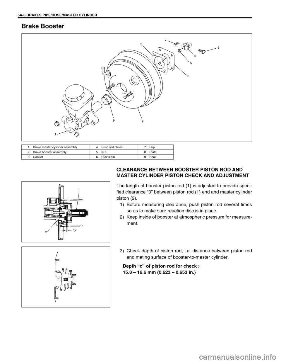
5A-8 BRAKES PIPE/HOSE/MASTER CYLINDER
Brake Booster
CLEARANCE BETWEEN BOOSTER PISTON ROD AND
MASTER CYLINDER PISTON CHECK AND ADJUSTMENT
The length of booster piston rod (1) is adjusted to provide speci-
fied clearance “0” between piston rod (1) end and master cylinder
piston (2).
1) Before measuring clearance, push piston rod several times
so as to make sure reaction disc is in place.
2) Keep inside of booster at atmospheric pressure for measure-
ment.
3) Check depth of piston rod, i.e. distance between piston rod
and mating surface of booster-to-master cylinder.
Depth “c” of piston rod for check :
15.8 – 16.6 mm (0.623 – 0.653 in.)
1. Brake master cylinder assembly 4. Push rod clevis 7. Clip
2. Brake booster assembly 5. Nut 8. Plate
3. Gasket 6. Clevis pin 9. Seal
19
2 3
8546 7
Page 116 of 656
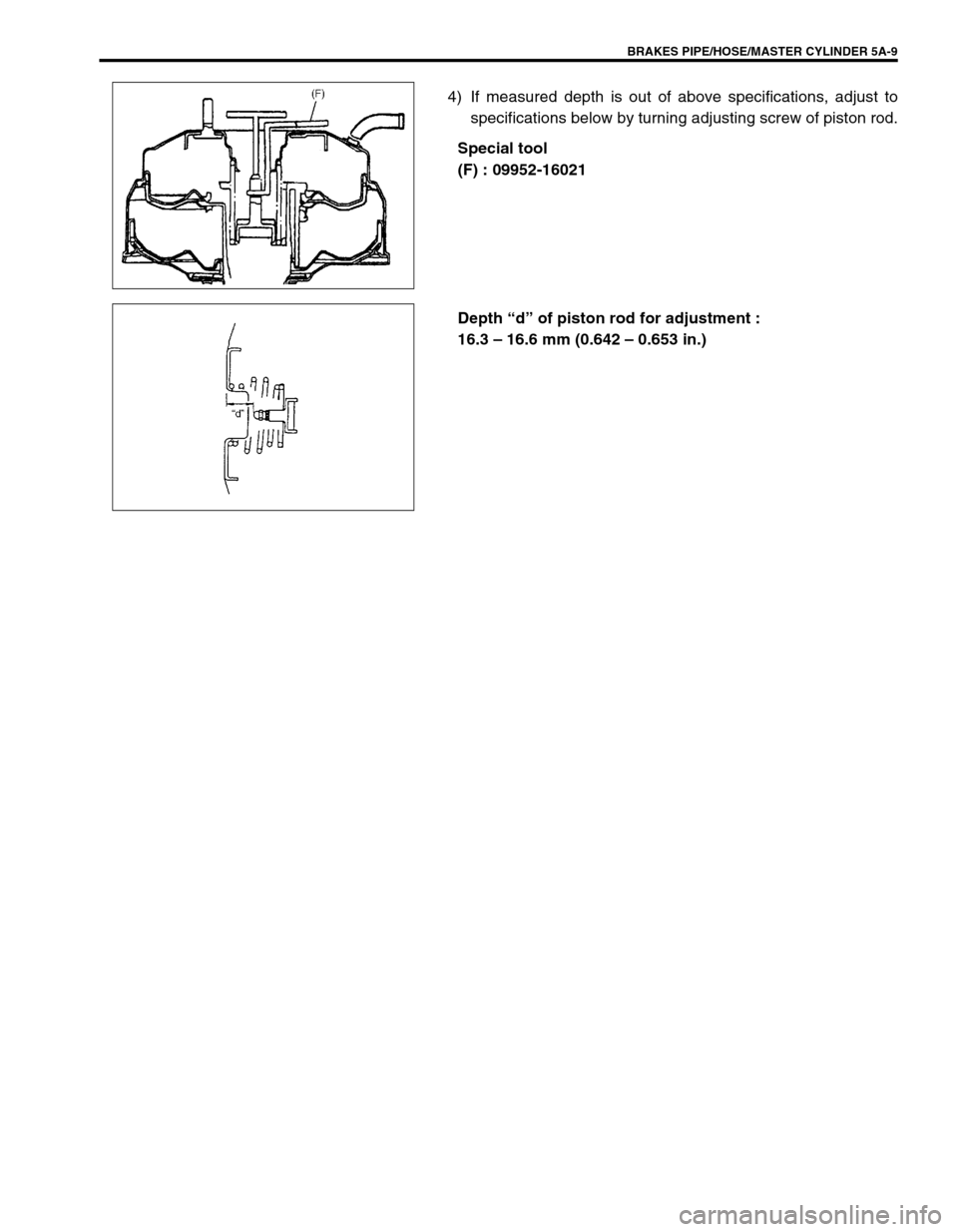
BRAKES PIPE/HOSE/MASTER CYLINDER 5A-9
4) If measured depth is out of above specifications, adjust to
specifications below by turning adjusting screw of piston rod.
Special tool
(F) : 09952-16021
Depth “d” of piston rod for adjustment :
16.3 – 16.6 mm (0.642 – 0.653 in.)
Page 117 of 656
5A-10 BRAKES PIPE/HOSE/MASTER CYLINDER
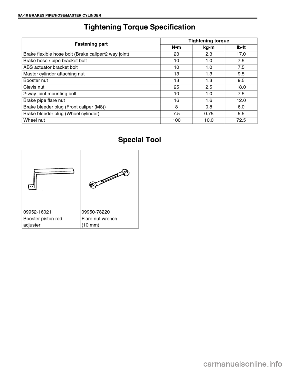
Tightening Torque Specification
Special Tool
Fastening partTightening torque
Nm kg-m lb-ft
Brake flexible hose bolt (Brake caliper/2 way joint) 23 2.3 17.0
Brake hose / pipe bracket bolt 10 1.0 7.5
ABS actuator bracket bolt 10 1.0 7.5
Master cylinder attaching nut 13 1.3 9.5
Booster nut 13 1.3 9.5
Clevis nut 25 2.5 18.0
2-way joint mounting bolt 10 1.0 7.5
Brake pipe flare nut 16 1.6 12.0
Brake bleeder plug (Front caliper (M8)) 8 0.8 6.0
Brake bleeder plug (Wheel cylinder) 7.5 0.75 5.5
Wheel nut 100 10.0 72.5
09952-16021 09950-78220
Booster piston rod
adjusterFlare nut wrench
(10 mm)
Page 118 of 656
PARKING AND REAR BRAKE 5C-1
5C
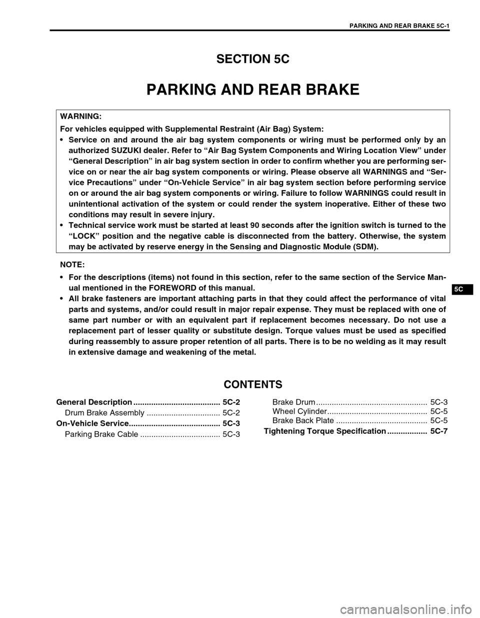
SECTION 5C
PARKING AND REAR BRAKE
CONTENTS
General Description ....................................... 5C-2
Drum Brake Assembly ................................. 5C-2
On-Vehicle Service......................................... 5C-3
Parking Brake Cable .................................... 5C-3Brake Drum .................................................. 5C-3
Wheel Cylinder............................................. 5C-5
Brake Back Plate ......................................... 5C-5
Tightening Torque Specification .................. 5C-7
WARNING:
For vehicles equipped with Supplemental Restraint (Air Bag) System:
Service on and around the air bag system components or wiring must be performed only by an
authorized SUZUKI dealer. Refer to “Air Bag System Components and Wiring Location View” under
“General Description” in air bag system section in order to confirm whether you are performing ser-
vice on or near the air bag system components or wiring. Please observe all WARNINGS and “Ser-
vice Precautions” under “On-Vehicle Service” in air bag system section before performing service
on or around the air bag system components or wiring. Failure to follow WARNINGS could result in
unintentional activation of the system or could render the system inoperative. Either of these two
conditions may result in severe injury.
Technical service work must be started at least 90 seconds after the ignition switch is turned to the
“LOCK” position and the negative cable is disconnected from the battery. Otherwise, the system
may be activated by reserve energy in the Sensing and Diagnostic Module (SDM).
NOTE:
For the descriptions (items) not found in this section, refer to the same section of the Service Man-
ual mentioned in the FOREWORD of this manual.
All brake fasteners are important attaching parts in that they could affect the performance of vital
parts and systems, and/or could result in major repair expense. They must be replaced with one of
same part number or with an equivalent part if replacement becomes necessary. Do not use a
replacement part of lesser quality or substitute design. Torque values must be used as specified
during reassembly to assure proper retention of all parts. There is to be no welding as it may result
in extensive damage and weakening of the metal.
Page 119 of 656
5C-2 PARKING AND REAR BRAKE
General Description
Drum Brake Assembly
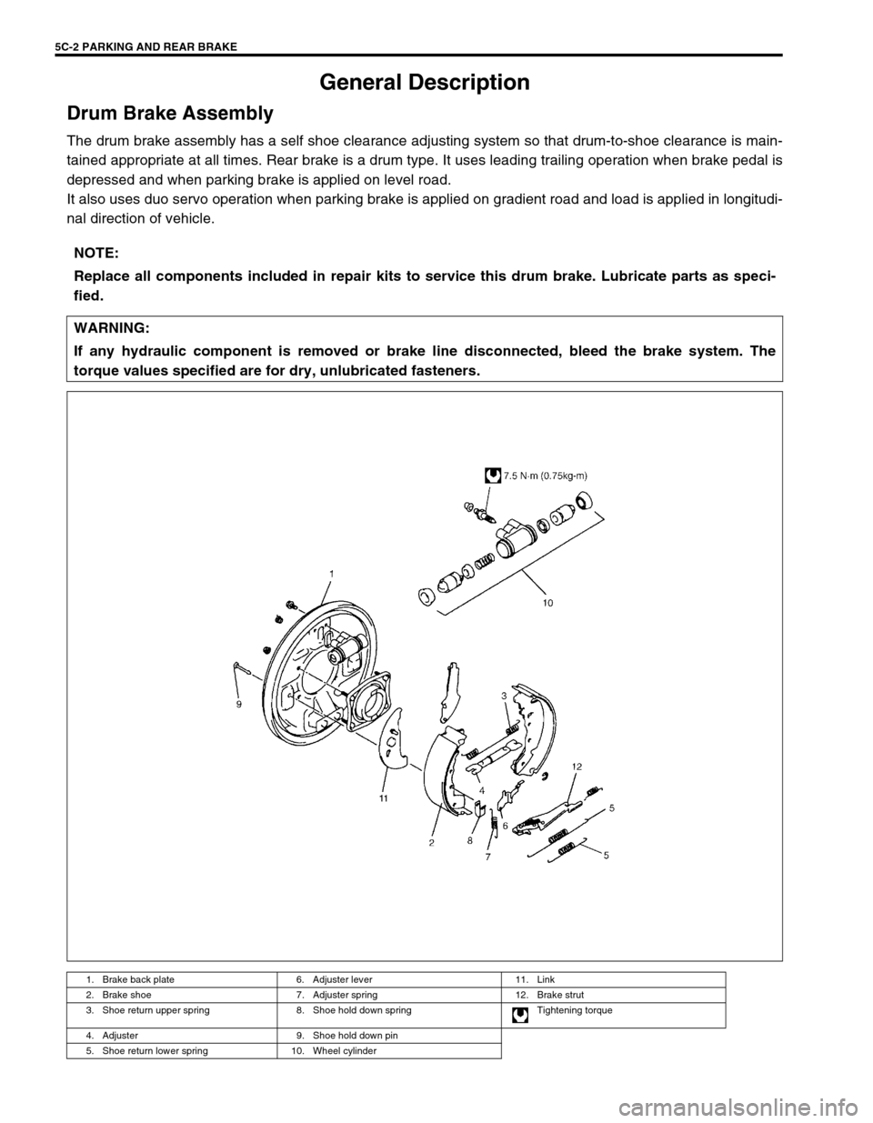
The drum brake assembly has a self shoe clearance adjusting system so that drum-to-shoe clearance is main-
tained appropriate at all times. Rear brake is a drum type. It uses leading trailing operation when brake pedal is
depressed and when parking brake is applied on level road.
It also uses duo servo operation when parking brake is applied on gradient road and load is applied in longitudi-
nal direction of vehicle.
NOTE:
Replace all components included in repair kits to service this drum brake. Lubricate parts as speci-
fied.
WARNING:
If any hydraulic component is removed or brake line disconnected, bleed the brake system. The
torque values specified are for dry, unlubricated fasteners.
1. Brake back plate 6. Adjuster lever 11. Link
2. Brake shoe 7. Adjuster spring 12. Brake strut
3. Shoe return upper spring 8. Shoe hold down spring Tightening torque
4. Adjuster 9. Shoe hold down pin
5. Shoe return lower spring 10. Wheel cylinder
Page 120 of 656
PARKING AND REAR BRAKE 5C-3
On-Vehicle Service
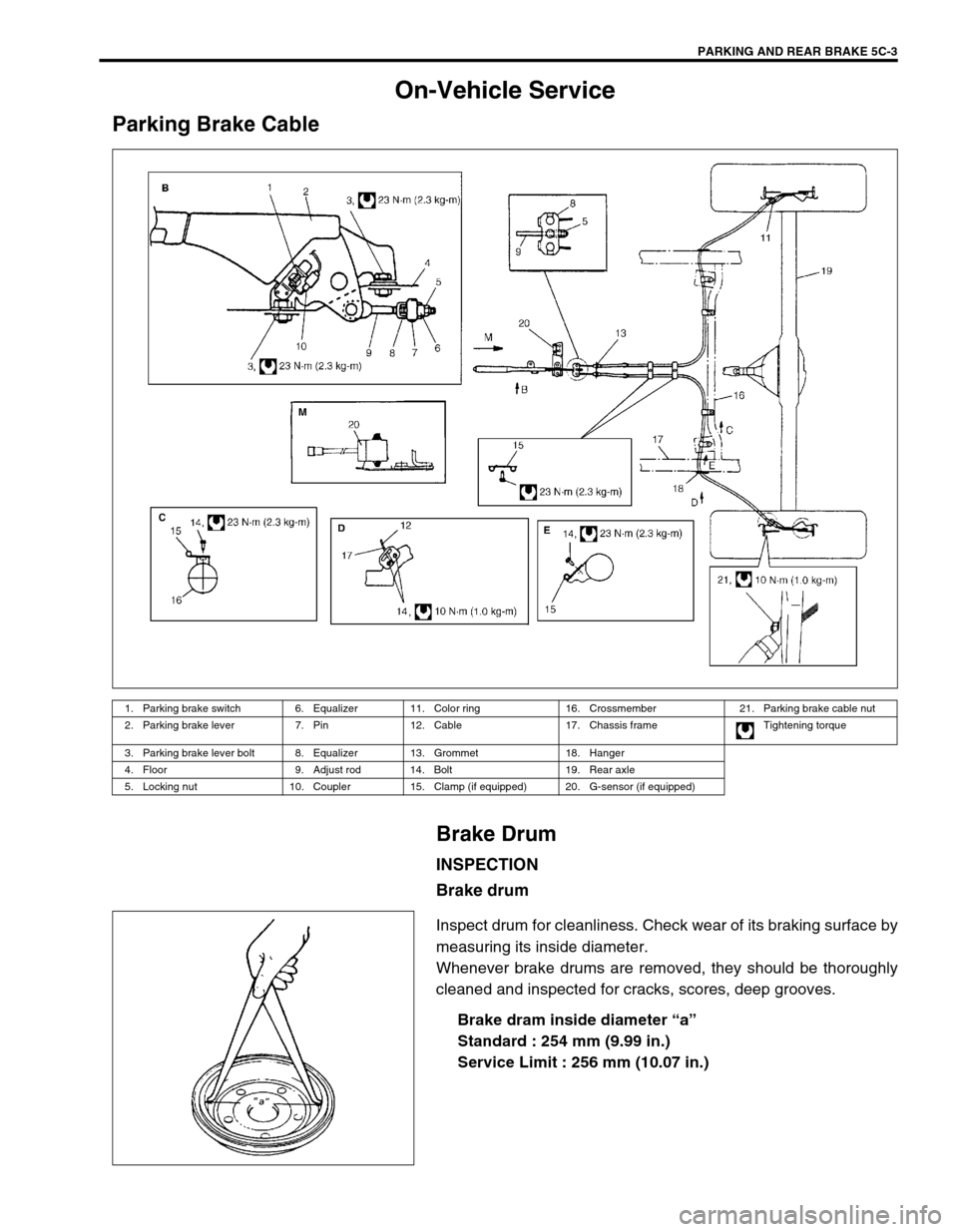
Parking Brake CableBrake Drum
INSPECTION
Brake drum
Inspect drum for cleanliness. Check wear of its braking surface by
measuring its inside diameter.
Whenever brake drums are removed, they should be thoroughly
cleaned and inspected for cracks, scores, deep grooves.Brake dram inside diameter “a ”
S ta n dard : 2 54 mm (9.99 in .)
S erv ic e L im it : 2 56 m m ( 10.07 i n.)
1. Parking brake switch 6. Equalizer 11. Color ring 16. Crossmember 21. Parking brake cable nut
2. Parking brake lever 7. Pin 12. Cable 17. Chassis frame Tightening torque
3. Parking brake lever bolt 8. Equalizer 13. Grommet 18. Hanger
4. Floor 9. Adjust rod 14. Bolt 19. Rear axle
5. Locking nut 10. Coupler 15. Clamp (if equipped) 20. G-sensor (if equipped)