SUZUKI GRAND VITARA 1999 2.G Owners Manual
Manufacturer: SUZUKI, Model Year: 1999, Model line: GRAND VITARA, Model: SUZUKI GRAND VITARA 1999 2.GPages: 656, PDF Size: 14.31 MB
Page 541 of 656
8E-20 CRUISE CONTROL SYSTEM
Coast/Set, Resume/Accel and Cancel
Switches
These switches are built in the combination switch assembly.
REMOVAL AND INSTALLATION
Refer to “COMBINATION SWITCH” in Section 3C1.
INSPECTION
1) Disable air bag system referring to “DISABLING AIR BAG
SYSTEM” in Section 10B.
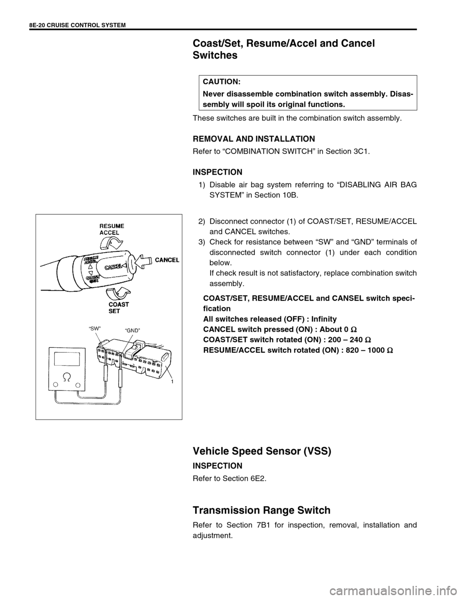
2) Disconnect connector (1) of COAST/SET, RESUME/ACCEL
and CANCEL switches.
3) Check for resistance between “SW” and “GND” terminals of
disconnected switch connector (1) under each condition
below.
If check result is not satisfactory, replace combination switch
assembly.
COAST/SET, RESUME/ACCEL and CANSEL switch speci-
fication
All switches released (OFF) : Infinity
CANCEL switch pressed (ON) : About 0 Ω
ΩΩ Ω
COAST/SET switch rotated (ON) : 200 – 240 Ω
ΩΩ Ω
RESUME/ACCEL switch rotated (ON) : 820 – 1000 Ω
ΩΩ Ω
Vehicle Speed Sensor (VSS)
INSPECTION
Refer to Section 6E2.
Transmission Range Switch
Refer to Section 7B1 for inspection, removal, installation and
adjustment.CAUTION:
Never disassemble combination switch assembly. Disas-
sembly will spoil its original functions.
Page 542 of 656
CRUISE CONTROL SYSTEM 8E-21
Clutch Pedal Position (CPP) Switch
REMOVAL
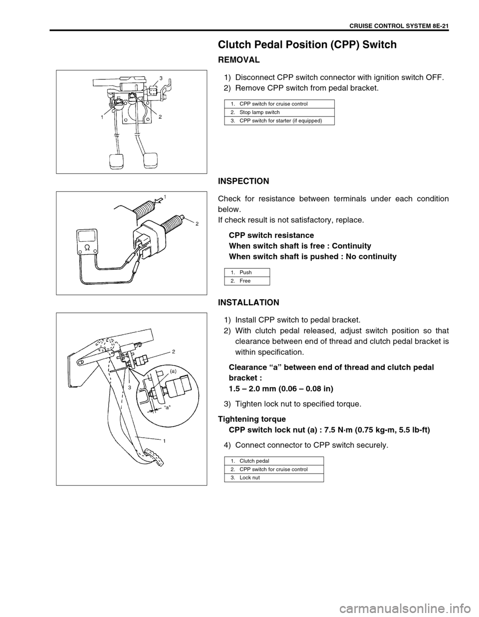
1) Disconnect CPP switch connector with ignition switch OFF.
2) Remove CPP switch from pedal bracket.
INSPECTION
Check for resistance between terminals under each condition
below.
If check result is not satisfactory, replace.
CPP switch resistance
When switch shaft is free : Continuity
When switch shaft is pushed : No continuity
INSTALLATION
1) Install CPP switch to pedal bracket.
2) With clutch pedal released, adjust switch position so that
clearance between end of thread and clutch pedal bracket is
within specification.
Clearance “a” between end of thread and clutch pedal
bracket :
1.5 – 2.0 mm (0.06 – 0.08 in)
3) Tighten lock nut to specified torque.
Tightening torque
CPP switch lock nut (a) : 7.5 N·m (0.75 kg-m, 5.5 lb-ft)
4) Connect connector to CPP switch securely.
1. CPP switch for cruise control
2. Stop lamp switch
3. CPP switch for starter (if equipped)
1. Push
2. Free
1. Clutch pedal
2. CPP switch for cruise control
3. Lock nut
Page 543 of 656
8E-22 CRUISE CONTROL SYSTEM
Stop Lamp Switch (with Pedal Position
Switch)
INSPECTION
1) Disconnect negative (–) cable at battery.
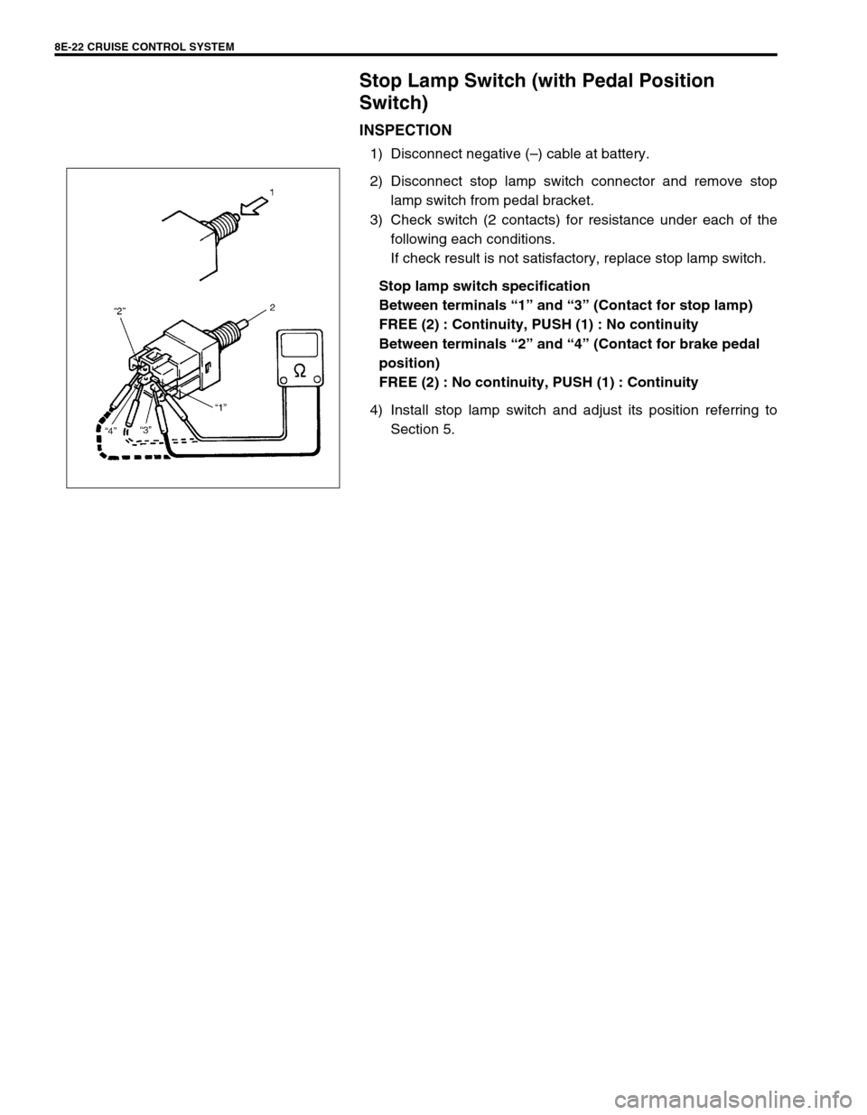
2) Disconnect stop lamp switch connector and remove stop
lamp switch from pedal bracket.
3) Check switch (2 contacts) for resistance under each of the
following each conditions.
If check result is not satisfactory, replace stop lamp switch.
Stop lamp switch specification
Between terminals “1” and “3” (Contact for stop lamp)
FREE (2) : Continuity, PUSH (1) : No continuity
Between terminals “2” and “4” (Contact for brake pedal
position)
FREE (2) : No continuity, PUSH (1) : Continuity
4) Install stop lamp switch and adjust its position referring to
Section 5.
Page 544 of 656
CRUISE CONTROL SYSTEM 8E-23
Cruise Control Actuator Assembly (with Con-
trol Module)
REMOVAL
1) Disconnect negative (–) cable at battery.
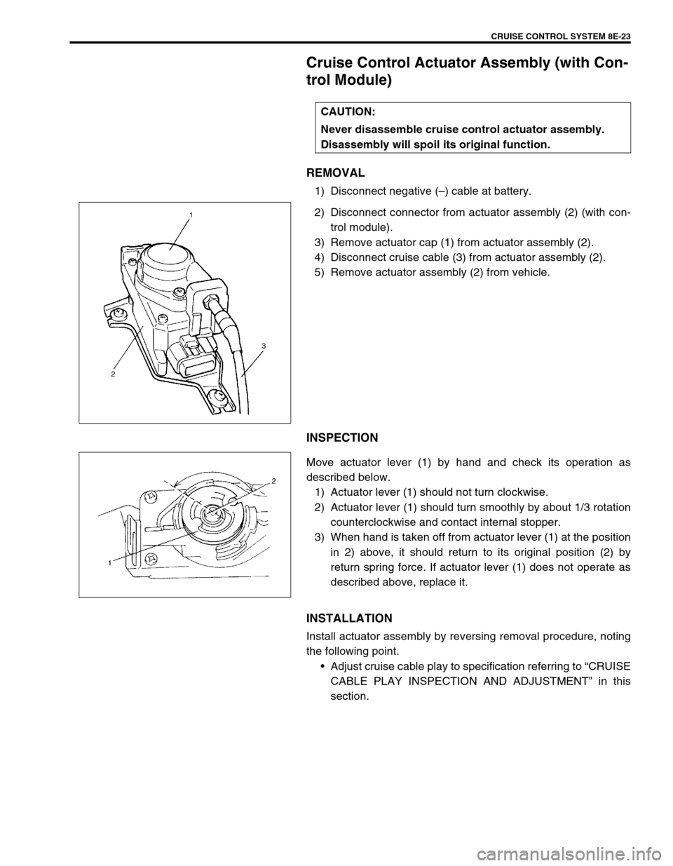
2) Disconnect connector from actuator assembly (2) (with con-
trol module).
3) Remove actuator cap (1) from actuator assembly (2).
4) Disconnect cruise cable (3) from actuator assembly (2).
5) Remove actuator assembly (2) from vehicle.
INSPECTION
Move actuator lever (1) by hand and check its operation as
described below.
1) Actuator lever (1) should not turn clockwise.
2) Actuator lever (1) should turn smoothly by about 1/3 rotation
counterclockwise and contact internal stopper.
3) When hand is taken off from actuator lever (1) at the position
in 2) above, it should return to its original position (2) by
return spring force. If actuator lever (1) does not operate as
described above, replace it.
INSTALLATION
Install actuator assembly by reversing removal procedure, noting
the following point.
•Adjust cruise cable play to specification referring to “CRUISE
CABLE PLAY INSPECTION AND ADJUSTMENT” in this
section. CAUTION:
Never disassemble cruise control actuator assembly.
Disassembly will spoil its original function.
Page 545 of 656
8E-24 CRUISE CONTROL SYSTEM
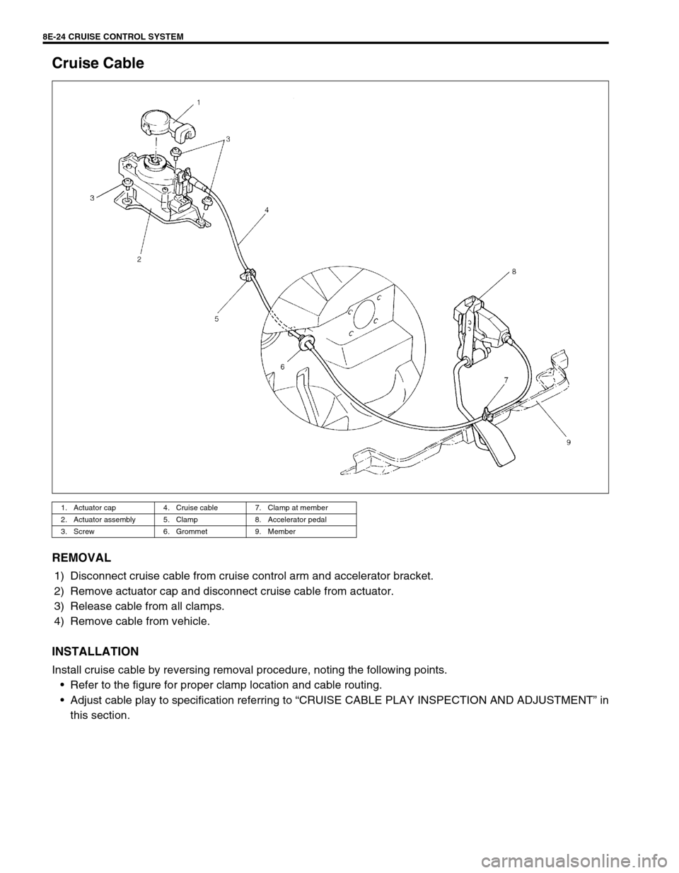
Cruise Cable
REMOVAL
1) Disconnect cruise cable from cruise control arm and accelerator bracket.
2) Remove actuator cap and disconnect cruise cable from actuator.
3) Release cable from all clamps.
4) Remove cable from vehicle.
INSTALLATION
Install cruise cable by reversing removal procedure, noting the following points.
•Refer to the figure for proper clamp location and cable routing.
•Adjust cable play to specification referring to “CRUISE CABLE PLAY INSPECTION AND ADJUSTMENT” in
this section.
1. Actuator cap 4. Cruise cable 7. Clamp at member
2. Actuator assembly 5. Clamp 8. Accelerator pedal
3. Screw 6. Grommet 9. Member
Page 546 of 656
BODY SERVICE 9-1
9
SECTION 9
BODY SERVICE
CONTENTS
Glass, Windows and Mirror .............................. 9-2
Quarter Window .............................................. 9-2
Body Structure .................................................. 9-3
Under Body Dimensions ................................. 9-3
Body Dimensions ............................................ 9-4
Seat..................................................................... 9-8
Second Seat .................................................... 9-8
Third Seat (If Equipped) .................................. 9-9
Paint and Coatings.......................................... 9-10Sealant Application Area............................... 9-10
Undercoating/Anti-corrosion Compound
Application Area ............................................ 9-17
Exterior and Interior Trim ............................... 9-19
Floor Carpet .................................................. 9-19
Front floor carpet ....................................... 9-19
Rear floor carpet (without third seat
vehicle) ...................................................... 9-20
Head Lining ................................................... 9-20
WARNING:
For vehicles equipped with Supplemental Restraint (Air Bag) System:
Service on and around the air bag system components or wiring must be performed only by an
authorized SUZUKI dealer. Refer to “Air Bag System Components and Wiring Location View” under
“General Description” in air bag system section in order to confirm whether you are performing ser-
vice on or near the air bag system components or wiring. Please observe all WARNINGS and “Ser-
vice Precautions” under “On-Vehicle Service” in air bag system section before performing service
on or around the air bag system components or wiring. Failure to follow WARNINGS could result in
unintentional activation of the system or could render the system inoperative. Either of these two
conditions may result in severe injury.
Technical service work must be started at least 90 seconds after the ignition switch is turned to the
“LOCK” position and the negative cable is disconnected from the battery. Otherwise, the system
may be activated by reserve energy in the Sensing and Diagnostic Module (SDM).
When body servicing, if shock may be applied to air bag system component parts, remove those
parts beforehand. (Refer to Section 10B.)
NOTE:
For the descriptions (items) not found in this section, refer to the same section of the Service Man-
ual mentioned in the FOREWORD of this manual.
Fasteners are important attaching parts in that they could affect the performance of vital compo-
nents and systems, and/or could result in major repair expense. They must be replaced with one of
the same part number of with an equivalent part if replacement becomes necessary.
Do not use a replacement part of lesser quality or substitute a design. Torque values must be used
as specified during reassembly to assure proper retention of these parts.
Page 547 of 656
9-2 BODY SERVICE
Glass, Windows and Mirror
Quarter Window
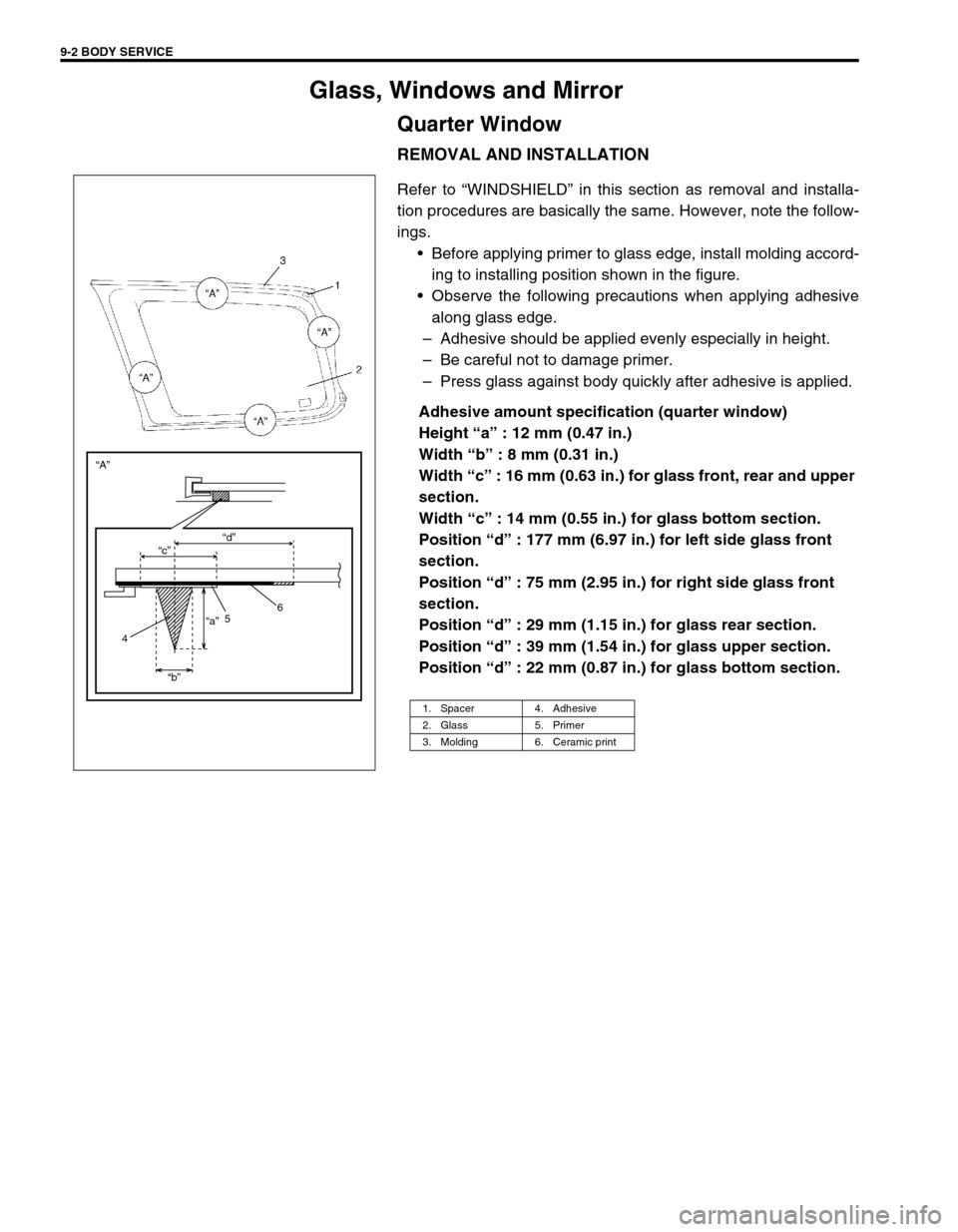
REMOVAL AND INSTALLATION
Refer to “WINDSHIELD” in this section as removal and installa-
tion procedures are basically the same. However, note the follow-
ings.
•Before applying primer to glass edge, install molding accord-
ing to installing position shown in the figure.
•Observe the following precautions when applying adhesive
along glass edge.
–Adhesive should be applied evenly especially in height.
–Be careful not to damage primer.
–Press glass against body quickly after adhesive is applied.
Adhesive amount specification (quarter window)
Height “a” : 12 mm (0.47 in.)
Width “b” : 8 mm (0.31 in.)
Width “c” : 16 mm (0.63 in.) for glass front, rear and upper
section.
Width “c” : 14 mm (0.55 in.) for glass bottom section.
Position “d” : 177 mm (6.97 in.) for left side glass front
section.
Position “d” : 75 mm (2.95 in.) for right side glass front
section.
Position “d” : 29 mm (1.15 in.) for glass rear section.
Position “d” : 39 mm (1.54 in.) for glass upper section.
Position “d” : 22 mm (0.87 in.) for glass bottom section.
1. Spacer 4. Adhesive
2. Glass 5. Primer
3. Molding 6. Ceramic print
“c” “A”
“a”
“b”“d”
6
5
4
Page 548 of 656
BODY SERVICE 9-3
Body Structure
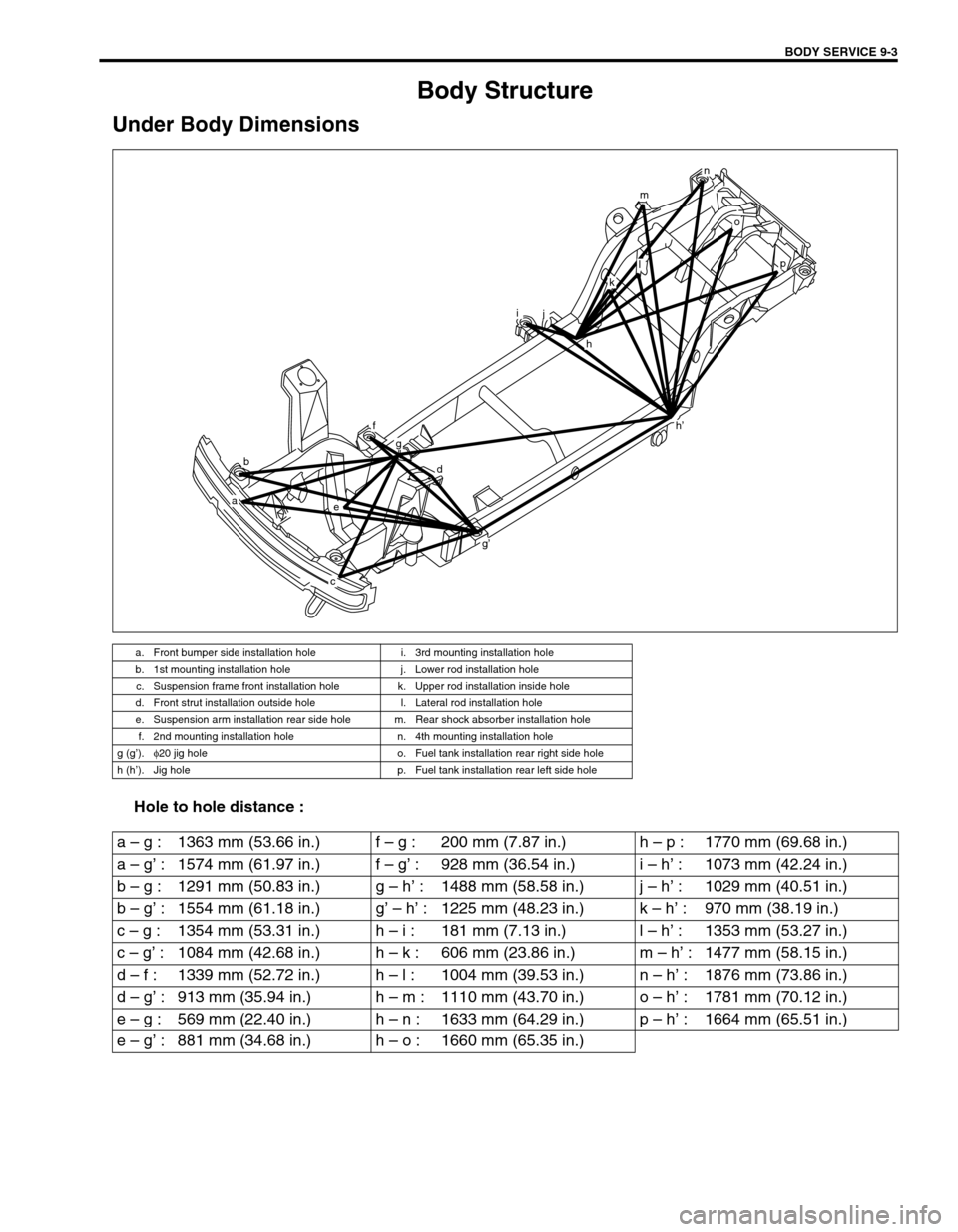
Under Body Dimensions
Hole to hole distance :
a. Front bumper side installation hole i. 3rd mounting installation hole
b. 1st mounting installation hole j. Lower rod installation hole
c. Suspension frame front installation hole k. Upper rod installation inside hole
d. Front strut installation outside hole l. Lateral rod installation hole
e. Suspension arm installation rear side hole m. Rear shock absorber installation hole
f. 2nd mounting installation hole n. 4th mounting installation hole
g (g’).φ
20 jig hole o. Fuel tank installation rear right side hole
h (h’). Jig hole p. Fuel tank installation rear left side hole
b
a
h’
e
f
g
d
g’
c
ij
h
o
p
n
m
l
k
a – g : 1363 mm (53.66 in.) f – g : 200 mm (7.87 in.) h – p : 1770 mm (69.68 in.)
a – g’ : 1574 mm (61.97 in.) f – g’ : 928 mm (36.54 in.) i – h’ : 1073 mm (42.24 in.)
b – g : 1291 mm (50.83 in.) g – h’ : 1488 mm (58.58 in.) j – h’ : 1029 mm (40.51 in.)
b – g’ : 1554 mm (61.18 in.) g’ – h’ : 1225 mm (48.23 in.) k – h’ : 970 mm (38.19 in.)
c – g : 1354 mm (53.31 in.) h – i : 181 mm (7.13 in.) l – h’ : 1353 mm (53.27 in.)
c – g’ : 1084 mm (42.68 in.) h – k : 606 mm (23.86 in.) m – h’ : 1477 mm (58.15 in.)
d – f : 1339 mm (52.72 in.) h – l : 1004 mm (39.53 in.) n – h’ : 1876 mm (73.86 in.)
d – g’ : 913 mm (35.94 in.) h – m : 1110 mm (43.70 in.) o – h’ : 1781 mm (70.12 in.)
e – g : 569 mm (22.40 in.) h – n : 1633 mm (64.29 in.) p – h’ : 1664 mm (65.51 in.)
e – g’ : 881 mm (34.68 in.) h – o : 1660 mm (65.35 in.)
Page 549 of 656
9-4 BODY SERVICE
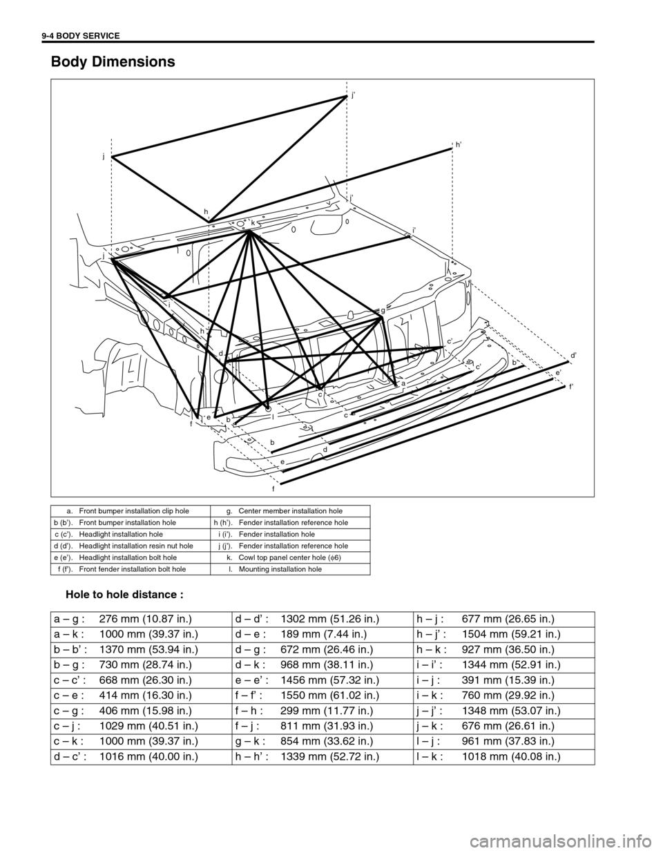
Body Dimensions
Hole to hole distance :
a. Front bumper installation clip hole g. Center member installation hole
b (b’). Front bumper installation hole h (h’). Fender installation reference hole
c (c’). Headlight installation hole i (i’). Fender installation hole
d (d’). Headlight installation resin nut hole j (j’). Fender installation reference hole
e (e’). Headlight installation bolt hole k. Cowl top panel center hole (φ
6)
f (f’). Front fender installation bolt hole l. Mounting installation hole
k
j’
j’
h’
j
j
i
h
h
febl
c
c
g
a
c’
i’
db’c’
d’
f’
e’
f
e
bd
a – g : 276 mm (10.87 in.) d – d’ : 1302 mm (51.26 in.) h – j : 677 mm (26.65 in.)
a – k : 1000 mm (39.37 in.) d – e : 189 mm (7.44 in.) h – j’ : 1504 mm (59.21 in.)
b – b’ : 1370 mm (53.94 in.) d – g : 672 mm (26.46 in.) h – k : 927 mm (36.50 in.)
b – g : 730 mm (28.74 in.) d – k : 968 mm (38.11 in.) i – i’ : 1344 mm (52.91 in.)
c – c’ : 668 mm (26.30 in.) e – e’ : 1456 mm (57.32 in.) i – j : 391 mm (15.39 in.)
c – e : 414 mm (16.30 in.) f – f’ : 1550 mm (61.02 in.) i – k : 760 mm (29.92 in.)
c – g : 406 mm (15.98 in.) f – h : 299 mm (11.77 in.) j – j’ : 1348 mm (53.07 in.)
c – j : 1029 mm (40.51 in.) f – j : 811 mm (31.93 in.) j – k : 676 mm (26.61 in.)
c – k : 1000 mm (39.37 in.) g – k : 854 mm (33.62 in.) l – j : 961 mm (37.83 in.)
d – c’ : 1016 mm (40.00 in.) h – h’ : 1339 mm (52.72 in.) l – k : 1018 mm (40.08 in.)
Page 550 of 656
BODY SERVICE 9-5
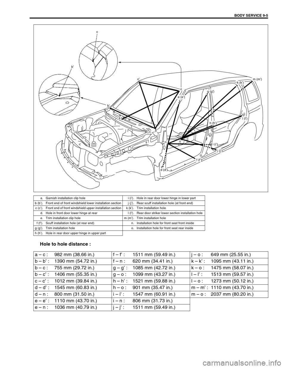
Hole to hole distance :
a. Garnish installation clip hole i (i’). Hole in rear door lower hinge in lower part
b (b’). Front end of front windshield lower installation section j (j’). Rear scuff installation hole (at front end)
c (c’). Front end of front windshield upper installation section k (k’). Trim installation hole
d. Hole in front door lower hinge at rear l (l’). Rear door striker lower section installation hole
e. Trim installation clip hole m (m’). Trim installation hole
f (f’). Scuff installation hole (at rear end) n. Installation hole for front seat front inside
g (g’). Trim installation hole o. Installation hole for front seat rear inside
h (h’). Hole in rear door upper hinge in upper part
c
b’
c’
b’
a
b
on
e (e’)
cg (g’)
h (h’)
i (i’)
j (j’)
l (l’)
m (m’)k (k’)
f (f’)
d (d’)
a – c : 982 mm (38.66 in.) f – f’ : 1511 mm (59.49 in.) j – o : 649 mm (25.55 in.)
b – b’ : 1390 mm (54.72 in.) f – n : 620 mm (34.41 in.) k – k’ : 1095 mm (43.11 in.)
b – c : 755 mm (29.72 in.) g – g’ : 1085 mm (42.72 in.) k – o : 1475 mm (58.07 in.)
b – c’ : 1406 mm (55.35 in.) g – o : 1099 mm (43.27 in.) l – l’ : 1513 mm (59.57 in.)
c – c’ : 1012 mm (39.84 in.) h – h’ : 1521 mm (59.88 in.) l – o : 1273 mm (50.12 in.)
d – d’ : 1545 mm (60.83 in.) h – o : 901 mm (35.47 in.) m – m’ : 1110 mm (43.70 in.)
d – n : 800 mm (31.50 in.) i – i’ : 1547 mm (60.91 in.) m – o : 2037 mm (80.20 in.)
e – e’ : 1110 mm (43.70 in.) i – n : 806 mm (31.73 in.)
e – n : 1036 mm (40.79 in.) j – j’ : 1511 mm (59.49 in.)