Engine fuel SUZUKI JIMNY 2005 3.G Service User Guide
[x] Cancel search | Manufacturer: SUZUKI, Model Year: 2005, Model line: JIMNY, Model: SUZUKI JIMNY 2005 3.GPages: 687, PDF Size: 13.38 MB
Page 41 of 687
Downloaded from www.Manualslib.com manuals search engine 0B-10 MAINTENANCE AND LUBRICATION
REPLACEMENT
Replace air cleaner filter with new one according to steps 1), 2)
and 5), 6) of inspection procedure.
Fuel Lines and Connections
INSPECTION
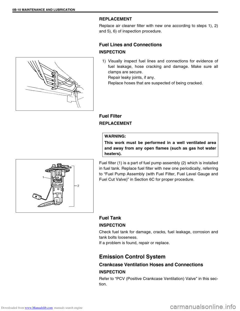
1) Visually inspect fuel lines and connections for evidence of
fuel leakage, hose cracking and damage. Make sure all
clamps are secure.
Repair leaky joints, if any.
Replace hoses that are suspected of being cracked.
Fuel Filter
REPLACEMENT
Fuel filter (1) is a part of fuel pump assembly (2) which is installed
in fuel tank. Replace fuel filter with new one periodically, referring
to “Fuel Pump Assembly (with Fuel Filter, Fuel Level Gauge and
Fuel Cut Valve)” in Section 6C for proper procedure.
Fuel Tank
INSPECTION
Check fuel tank for damage, cracks, fuel leakage, corrosion and
tank bolts looseness.
If a problem is found, repair or replace.
Emission Control System
Crankcase Ventilation Hoses and Connections
INSPECTION
Refer to “PCV (Positive Crankcase Ventilation) Valve” in this sec-
tion.
WARNING:
This work must be performed in a well ventilated area
and away from any open flames (such as gas hot water
heaters).
Page 42 of 687
Downloaded from www.Manualslib.com manuals search engine MAINTENANCE AND LUBRICATION 0B-11
PCV (Positive Crankcase Ventilation) Valve
INSPECTION
Check crankcase ventilation hose and PCV hose for leaks, cracks
or clog, and PCV valve for stick or clog. Refer to “PCV System” of
Section 6E for PCV valve checking procedure.
Fuel Evaporative Emission Control System
INSPECTION
1) Visually inspect hoses for cracks, damage, or excessive
bends. Inspect all clamps for damage and proper position.
2) Check EVAP canister for operation and clog, referring to
“Evaporative Emission (EVAP) Control System” in Section
6E.
If a malfunction is found, repair or replace.
Chassis and Body
Clutch
INSPECTION
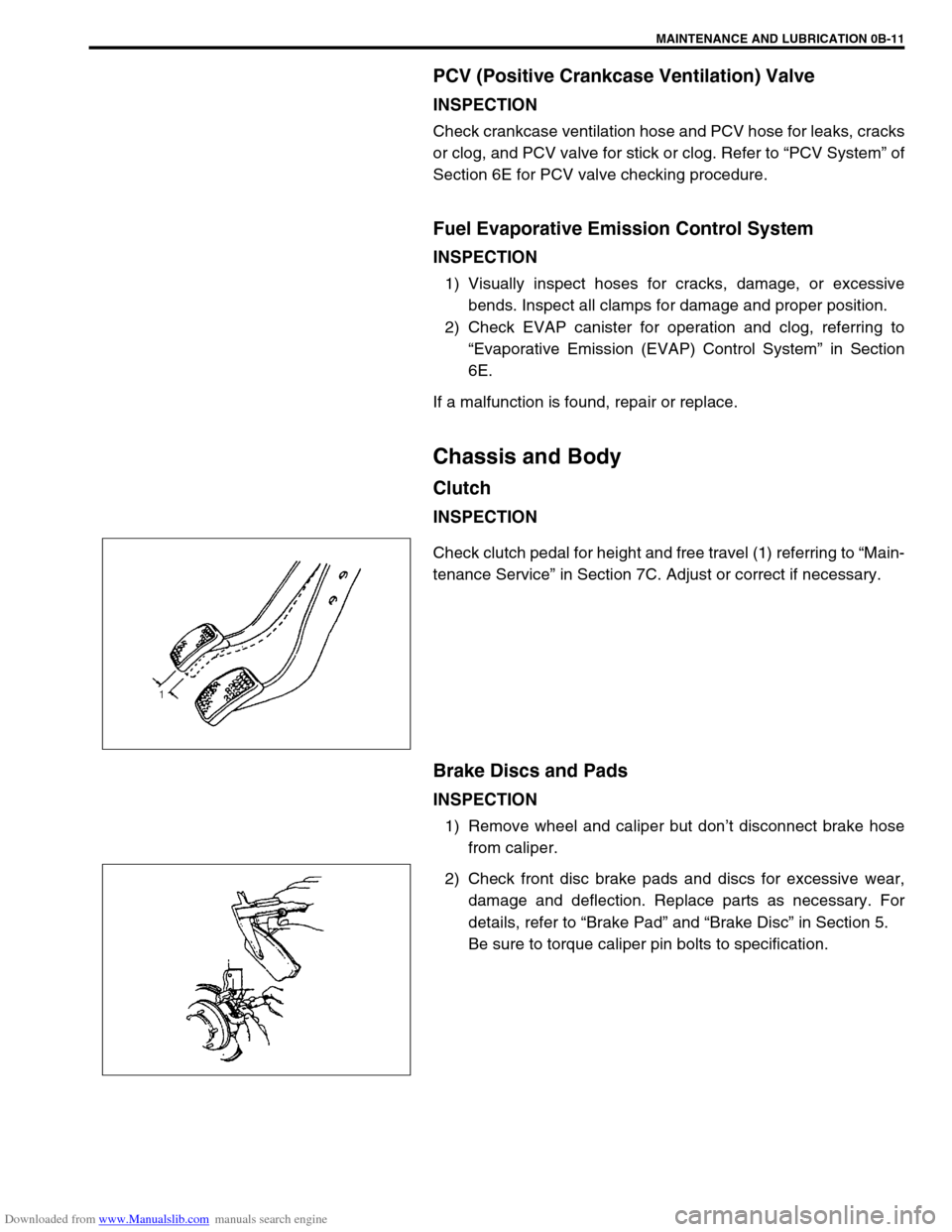
Check clutch pedal for height and free travel (1) referring to “Main-
tenance Service” in Section 7C. Adjust or correct if necessary.
Brake Discs and Pads
INSPECTION
1) Remove wheel and caliper but don’t disconnect brake hose
from caliper.
2) Check front disc brake pads and discs for excessive wear,
damage and deflection. Replace parts as necessary. For
details, refer to “Brake Pad” and “Brake Disc” in Section 5.
Be sure to torque caliper pin bolts to specification.
Page 52 of 687

Downloaded from www.Manualslib.com manuals search engine MAINTENANCE AND LUBRICATION 0B-21
GEARSHIFT OR SELECTOR LEVER (TRANSMISSION)
Check gear shift or selector lever for smooth shifting to all positions and for good performance of transmission in
any position.
With automatic transmission equipped vehicle, also check that shift indicator indicates properly according to
which position selector lever is shifted to.
With automatic transmission equipped vehicle, make sure that vehicle is at complete stop when shifting selector
lever to “P” range position and release all brakes.
BRAKE
Foot Brake
Check the following:
that brake pedal has proper travel,
that brake works properly,
that it is free from noise,
that braking force is applied equally on all wheels,
and that brake do not drag.
Parking Brake
Check that lever has proper travel.
Check to ensure that parking brake is fully effective when the vehicle is stopped on the safe slope and brake
lever is pulled all the way.
STEERING
Check to ensure that steering wheel is free from instability, or abnormally heavy feeling.
Check that the vehicle does not wander or pull to one side.
ENGINE
Check that engine responds readily at all speeds.
Check that engine is free from abnormal noise and abnormal vibration.
BODY, WHEELS AND POWER TRANSMITTING SYSTEM
Check that body, wheels and power transmitting system are free from abnormal noise and abnormal vibration or
any other abnormal condition.
METERS AND GAUGE
Check that speedometer, odometer, fuel meter, temperature gauge, etc. are operating accurately.
LIGHTS
Check that all lights operate properly.
WINDSHIELD DEFROSTER
Periodically check that air comes out from defroster outlet when operating heater or air conditioning.
Set mode control lever to defroster position and fan switch lever to “HI” position for this check. WARNING:
With vehicle parked on a fairly steep slope, make sure nothing is in the way downhill to avoid any per-
sonal injury or property damage. Be prepared to apply regular brake quickly even if vehicle should
start to move.
Page 250 of 687
Downloaded from www.Manualslib.com manuals search engine WHEELS AND TIRES 3F-7
Lower than Recommended Pressure Can Cause:
1) Tire squeal on turns
2) Hard steering
3) Rapid and uneven wear on the edges of the tread
4) Tire rim bruises and rupture
5) Tire cord breakage
6) High tire temperatures
7) Reduced handling
8) High fuel consumption
Tire placard
The tire placard is located on the driver’s side door lock pillar and should be referred to for tire information. The
placard lists the maximum load, tire size and cold tire pressure where applicable.
Tire rotation
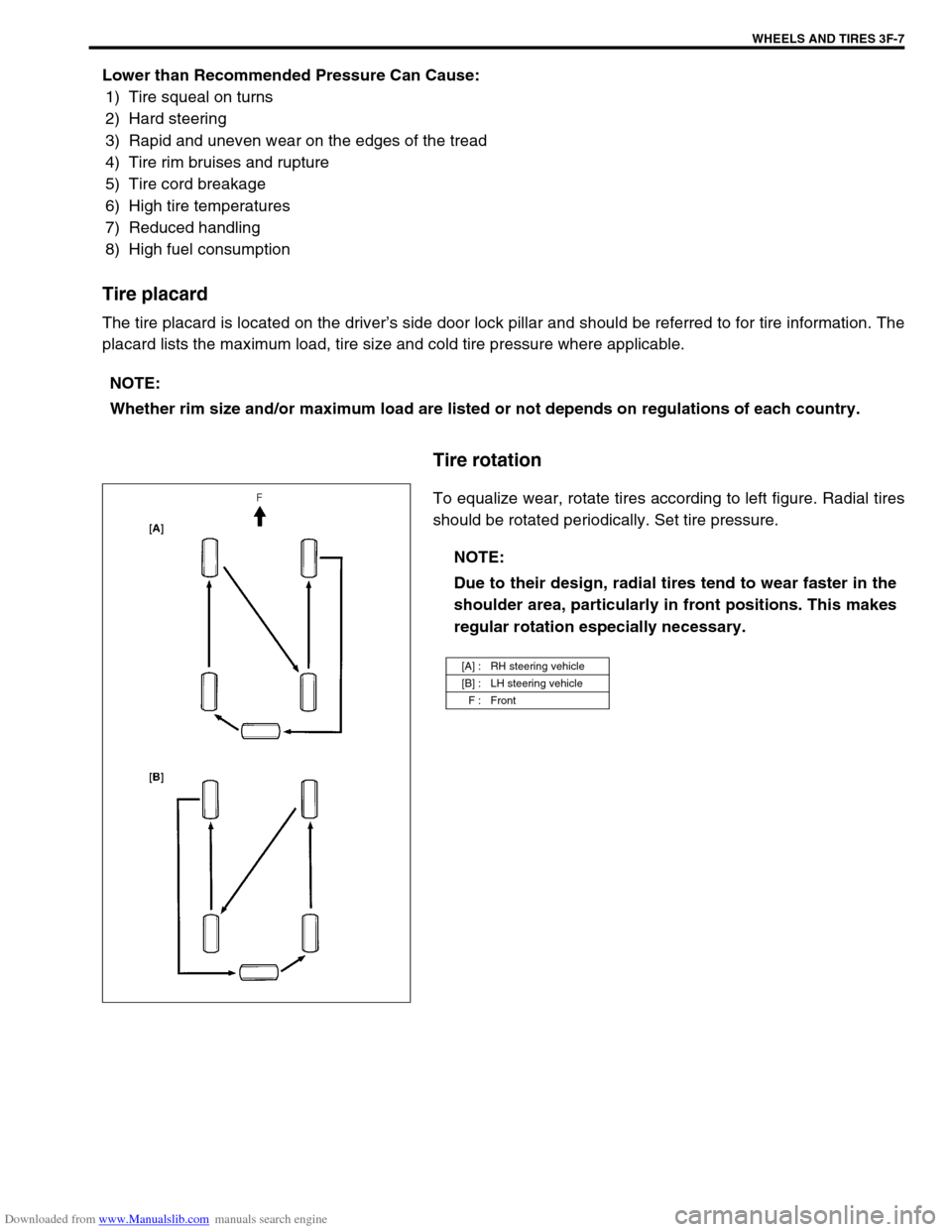
To equalize wear, rotate tires according to left figure. Radial tires
should be rotated periodically. Set tire pressure. NOTE:
Whether rim size and/or maximum load are listed or not depends on regulations of each country.
NOTE:
Due to their design, radial tires tend to wear faster in the
shoulder area, particularly in front positions. This makes
regular rotation especially necessary.
[A] : RH steering vehicle
[B] : LH steering vehicle
F : Front
Page 276 of 687
Downloaded from www.Manualslib.com manuals search engine BRAKES 5-15
Fluid Pressure Test (If Equipped with LSPV)
Test procedure for LSPV assembly is as follows.
Before testing, confirm the following.
Fuel tank is filled with fuel fully.
Vehicle is equipped with spare tire, tools, jack and jack han-
dle.
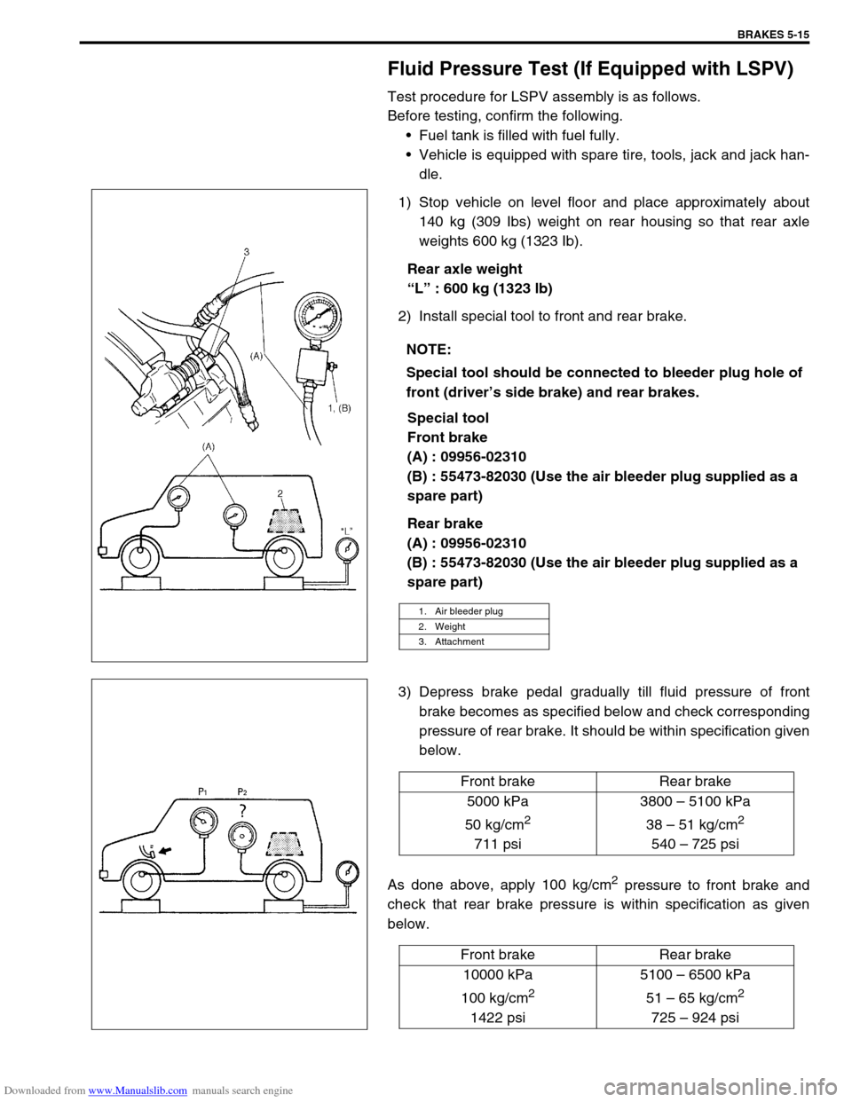
1) Stop vehicle on level floor and place approximately about
140 kg (309 Ibs) weight on rear housing so that rear axle
weights 600 kg (1323 Ib).
Rear axle weight
“L” : 600 kg (1323 lb)
2) Install special tool to front and rear brake.
Special tool
Front brake
(A) : 09956-02310
(B) : 55473-82030 (Use the air bleeder plug supplied as a
spare part)
Rear brake
(A) : 09956-02310
(B) : 55473-82030 (Use the air bleeder plug supplied as a
spare part)
3) Depress brake pedal gradually till fluid pressure of front
brake becomes as specified below and check corresponding
pressure of rear brake. It should be within specification given
below.
As done above, apply 100 kg/cm
2 pressure to front brake and
check that rear brake pressure is within specification as given
below.NOTE:
Special tool should be connected to bleeder plug hole of
front (driver’s side brake) and rear brakes.
1. Air bleeder plug
2. Weight
3. Attachment
Front brake Rear brake
5000 kPa
50 kg/cm
2
711 psi3800 – 5100 kPa
38 – 51 kg/cm
2
540 – 725 psi
Front brake Rear brake
10000 kPa
100 kg/cm
2
1422 psi5100 – 6500 kPa
51 – 65 kg/cm
2
725 – 924 psi
Page 304 of 687
Downloaded from www.Manualslib.com manuals search engine BRAKES 5-43
LSPV Assembly
INSPECTION AND ADJUSTMENT
1) Confirm the following before inspection and adjustment.
Fuel tank is filled with fuel fully.
Vehicle is equipped with spare tire, tools, jack and jack han-
dle.
Vehicle is free from any other load.
Place it on level floor.
2) Push up LSPV lever with finger till it stops and measure
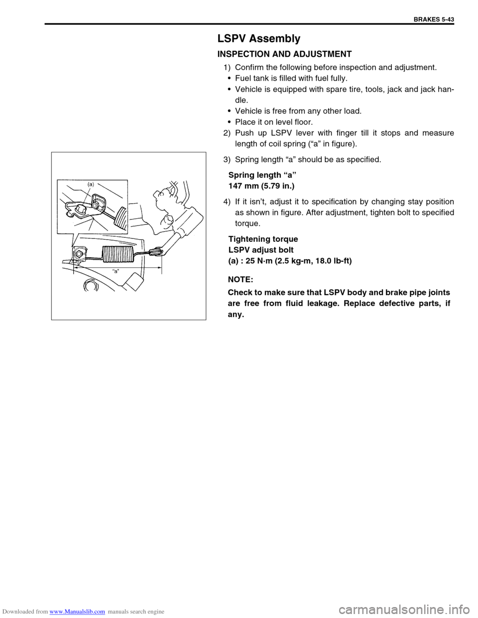
length of coil spring (“a” in figure).
3) Spring length “a” should be as specified.
Spring length “a”
147 mm (5.79 in.)
4) If it isn’t, adjust it to specification by changing stay position
as shown in figure. After adjustment, tighten bolt to specified
torque.
Tightening torque
LSPV adjust bolt
(a) : 25 N·m (2.5 kg-m, 18.0 lb-ft)
NOTE:
Check to make sure that LSPV body and brake pipe joints
are free from fluid leakage. Replace defective parts, if
any.
Page 312 of 687
Downloaded from www.Manualslib.com manuals search engine BRAKES 5-51
Rear Brake Hose/Pipe
REMOVAL
1) Raise, suitably support vehicle. Remove wheel if necessary.
2) Clean dirt and foreign material from both hose end or pipe end fittings. Remove brake hose and pipe.
INSTALLATION
1) Install brake hose and pipe by reversing removal procedure, noting the following points.
Fill and maintain brake fluid level in reservoir. Bleed brake system.
2) Perform brake test and check each installed part for fluid leakage.
CAUTION:
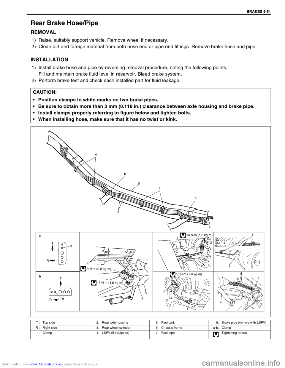
Position clamps to white marks on two brake pipes.
Be sure to obtain more than 3 mm (0.118 in.) clearance between axle housing and brake pipe.
Install clamps properly referring to figure below and tighten bolts.
When installing hose, make sure that it has no twist or kink.
T : Top side 2. Rear axle housing 5. Fuel tank 8. Brake pipe (vehicle with LSPV)
R : Right side 3. Rear wheel cylinder 6. Chassis frame a-b: Clamp
1. Clamp 4. LSPV (if equipped) 7. Fuel pipe Tightening torque
Page 358 of 687
Downloaded from www.Manualslib.com manuals search engine ENGINE GENERAL INFORMATION AND DIAGNOSIS 6-1
6F2
6G
6H
6K
7A
7A1
7B1
7C1
7D
7E
7F
8B
6
8D
8E
8B
9
10A
10B
SECTION 6
ENGINE GENERAL INFORMATION AND
DIAGNOSIS
GENERAL INFORMATION AND ENGINE DIAGNOSIS ..............................................................................
6-1
ENGINE MECHANICAL ...........................................................................................................................
6A1-1
ENGINE COOLING.....................................................................................................................................
6B-1
ENGINE FUEL ............................................................................................................................................
6C-1
ENGINE AND EMISSION CONTROL SYSTEM ........................................................................................
6E-1
IGNITION SYSTEM ....................................................................................................................................
6F-1
CRANKING SYSTEM .................................................................................................................................
6G-1
CHARGING SYSTEM .................................................................................................................................
6H-1
EXHAUST SYSTEM ...................................................................................................................................
6K-1
CONTENTS
General Information .......................................... 6-3
Statement on Cleanliness and Care ............... 6-3
General Information on Engine Service .......... 6-3
Precaution on fuel system service............... 6-4
Fuel pressure relief procedure .................... 6-5
Fuel leakage check procedure .................... 6-5
Engine Diagnosis .............................................. 6-6
General Description ........................................ 6-6
On-Board Diagnostic System (Vehicle with
Immobilizer Indicator Lamp) ............................ 6-6On-Board Diagnostic System (Vehicle without
Immobilizer Indicator Lamp)............................ 6-9
Precaution in Diagnosing Trouble ................. 6-10
Engine Diagnostic Flow Table ...................... 6-11
Customer problem inspection form
(example) .................................................. 6-13
Malfunction indicator lamp (MIL) check..... 6-14
Diagnostic trouble code (DTC) check ....... 6-14
Diagnostic trouble code (DTC)
clearance................................................... 6-15 WARNING:
For vehicles equipped with Supplemental Restraint (Air Bag) System :
Service on and around the air bag system components or wiring must be performed only by an
authorized SUZUKI dealer. Refer to “Air Bag System Components and Wiring Location View” under
“General Description” in air bag system section in order to confirm whether you are performing ser-
vice on or near the air bag system components or wiring. Please observe all WARNINGS and “Ser-
vice Precautions” under “On-Vehicle Service” in air bag system section before performing service
on or around the air bag system components or wiring. Failure to follow WARNINGS could result in
unintentional activation of the system or could render the system inoperative. Either of these two
conditions may result in severe injury.
Technical service work must be started at least 90 seconds after the ignition switch is turned to the
“LOCK” position and the negative cable is disconnected from the battery. Otherwise, the system
may be activated by reserve energy in the Sensing and Diagnostic Module (SDM).
NOTE:
Whether the following systems (parts) are used in the particular vehicle or not depends on vehicle
specifications. Be sure to bear this in mind when performing service work.
EGR valve
Heated oxygen sensor(s) or CO adjusting resistor
Three-way catalytic converter (TWC) and warm up three-way catalytic converter (WU-TWC)
Page 359 of 687

Downloaded from www.Manualslib.com manuals search engine 6-2 ENGINE GENERAL INFORMATION AND DIAGNOSIS
Diagnostic trouble code (DTC) table ......... 6-16
Fail-safe table............................................ 6-19
Visual inspection ....................................... 6-20
Engine basic inspection ............................ 6-21
Engine diagnosis table .............................. 6-23
Scan Tool Data ............................................. 6-28
Scan tool data definitions .......................... 6-30
Inspection of ECM and Its Circuits ................ 6-33
Component Location ..................................... 6-42
Table A-1 Malfunction Indicator Lamp Circuit
Check - Lamp Does Not Come “ON” at Ignition
Switch ON (But Engine at Stop).................... 6-43
Table A-2 Malfunction Indicator Lamp Circuit
Check - Lamp Remains “ON” after Engine
Starts............................................................. 6-44
Table A-3 Malfunction Indicator Lamp Circuit
Check - Mil Flashes at Ignition Switch ON .... 6-45
Table A-4 Malfunction Indicator Lamp Circuit
Check - MIL Does Not Flash, Just Remains
ON or Just Remains OFF Even with Grounding
Diagnosis Switch Terminal............................ 6-45
Table A-5 ECM Power and Ground Circuit
Check - MIL Doesn’t Light at Ignition Switch
ON and Engine Doesn’t Start Though It Is
Cranked Up ................................................... 6-46
DTC P0105 (DTC No.11) Manifold Absolute
Pressure (MAP) Circuit Malfunction .............. 6-48
DTC P0110 (DTC No.18) Intake Air Temp.
(IAT) Circuit Malfunction ............................... 6-51
DTC P0115 (DTC No.19) Engine Coolant
Temperature (ECT) Circuit Malfunction ........ 6-53
DTC P0120 (DTC No.13) Throttle Position
Circuit Malfunction ........................................ 6-55
DTC P0121 Throttle Position Circuit Range /
Performance Problem ................................... 6-57
DTC P0130 (DTC No.14) Heated Oxygen
Sensor (HO2S) Circuit Malfunction
(Sensor-1) ..................................................... 6-59
DTC P0133 Heated Oxygen Sensor (HO2S)
Circuit Slow Response (Sensor-1) ................ 6-61
DTC P0135 (DTC No.14) Heated Oxygen
Sensor (HO2S) Heater Circuit Malfunction
(Sensor-1) ..................................................... 6-62
DTC P0136 Heated Oxygen Sensor (HO2S)
Circuit Malfunction (Sensor-2) ...................... 6-64
DTC P0141 Heated Oxygen Sensor (HO2S)
Heater Circuit Malfunction (Sensor-2)........... 6-66
DTC P0171 Fuel System Too Lean .............. 6-68
DTC P0172 Fuel System Too Rich ............... 6-68
DTC P0300 Random Misfire Detected
(Misfire Detected at 2 or More Cylinders) ..... 6-72DTC P0301 Cylinder 1 Misfire Detected ........ 6-72
DTC P0302 Cylinder 2 Misfire Detected ........ 6-72
DTC P0303 Cylinder 3 Misfire Detected ........ 6-72
DTC P0304 Cylinder 4 Misfire Detected ........ 6-72
DTC P0325 (DTC No.17) Knock Sensor Circuit
Malfunction .................................................... 6-77
DTC P0335 (DTC No.23) Crankshaft Position
(CKP) Sensor Circuit Malfunction .................. 6-79
DTC P0340 (DTC No.15) Camshaft Position
(CMP) Sensor Circuit Malfunction ................. 6-82
DTC P0400 Exhaust Gas Recirculation Flow
Malfunction .................................................... 6-85
DTC P0420 Catalyst System Efficiency below
Threshold ....................................................... 6-88
DTC P0443 Purge Control Valve Circuit
Malfunction .................................................... 6-91
DTC P0481 A/C Condenser Fan Control
Circuit Malfunction ......................................... 6-92
DTC P0500 (DTC No.16) Vehicle Speed
Sensor (VSS) Malfunction ............................. 6-94
DTC P0505 Idle Control System
Malfunction .................................................... 6-96
DTC P0601 Internal Control Module Memory
Check Sum Error (DTC No.71) ...................... 6-98
DTC P1450 Barometric Pressure Sensor
Low / High Input ............................................. 6-99
DTC P1451 Barometric Pressure Sensor
Performance Problem .................................... 6-99
DTC P1500 Engine Starter Signal Circuit
Malfunction .................................................. 6-101
DTC P1510 ECM Back-up Power Supply
Malfunction .................................................. 6-103
DTC P1570 (DTC No.21) ABS Signal Circuit
Malfunction .................................................. 6-104
DTC P1600 Serial Communication Problem
Between ECM and TCM .............................. 6-105
DTC P1717 A/T Drive Range (Park / Neutral
Position) Signal Circuit Malfunction ............. 6-107
Table B-1 Fuel Injector Circuit Check ..........6-109
Table B-2 Fuel Pump and Its Circuit
Check........................................................... 6-110
Table B-3 Fuel Pressure Check................... 6-112
Table B-4 Idle Air Control System Check ....6-114
Table B-5 A/C Signal Circuits Check
(Vehicle with A/C) ........................................ 6-117
Table B-6 Electric Load Signal Circuit
Check........................................................... 6-119
TAble B-7 A/C Condenser Fan Control
System Check.............................................. 6-121
Special Tool ................................................... 6-123
Page 361 of 687
Downloaded from www.Manualslib.com manuals search engine 6-4 ENGINE GENERAL INFORMATION AND DIAGNOSIS
Precaution on fuel system service
Work must be done with no smoking, in a well-ventilated
area and away from any open flames.
As fuel feed line (between fuel pump and fuel delivery pipe)
is still under high fuel pressure even after engine was
stopped, loosening or disconnecting fuel feed line directly
may cause dangerous spout of fuel to occur where loosened
or disconnected.
Before loosening or disconnecting fuel feed line, make sure
to release fuel pressure according to “FUEL PRESSURE
RELIEF PROCEDURE”. A small amount of fuel may be
released after the fuel line is disconnected. In order to
reduce the chance of personal injury, cover the fitting to be
disconnected with a shop cloth. Put that cloth in an approved
container when disconnection is completed.
Never run engine with fuel pump relay disconnected when
engine and exhaust system are hot.
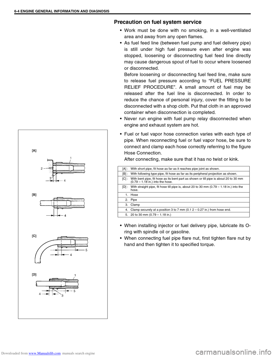
Fuel or fuel vapor hose connection varies with each type of
pipe. When reconnecting fuel or fuel vapor hose, be sure to
connect and clamp each hose correctly referring to the figure
Hose Connection.
After connecting, make sure that it has no twist or kink.
When installing injector or fuel delivery pipe, lubricate its O-
ring with spindle oil or gasoline.
When connecting fuel pipe flare nut, first tighten flare nut by
hand and then tighten it to specified torque.
[A] : With short pipe, fit hose as far as it reaches pipe joint as shown.
[B] : With following type pipe, fit hose as far as its peripheral projection as shown.
[C] : With bent pipe, fit hose as its bent part as shown or till pipe is about 20 to 30 mm
(0.79 – 1.18 in.) into the hose.
[D] : With straight pipe, fit hose till pipe is, about 20 to 30 mm (0.79 – 1.18 in.) into the
hose.
1. Hose
2. Pipe
3. Clamp
4. Clamp securely at a position 3 to 7 mm (0.1 2 – 0.27 in.) from hose end.
5. 20 to 30 mm (0.79 – 1.18 in.)