engine SUZUKI JIMNY 2005 3.G Service Workshop Manual
[x] Cancel search | Manufacturer: SUZUKI, Model Year: 2005, Model line: JIMNY, Model: SUZUKI JIMNY 2005 3.GPages: 687, PDF Size: 13.38 MB
Page 251 of 687
Downloaded from www.Manualslib.com manuals search engine 3F-8 WHEELS AND TIRES
On-Vehicle Service
Wheel
REMOVAL
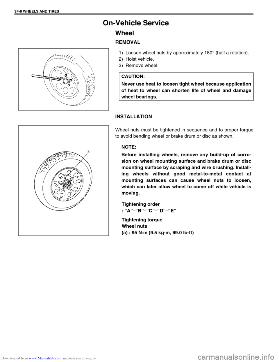
1) Loosen wheel nuts by approximately 180° (half a rotation).
2) Hoist vehicle.
3) Remove wheel.
INSTALLATION
Wheel nuts must be tightened in sequence and to proper torque
to avoid bending wheel or brake drum or disc as shown.
Tightening order
: “A”–“B”–“C”–“D”–“E”
Tightening torque
Wheel nuts
(a) : 95 N·m (9.5 kg-m, 69.0 lb-ft) CAUTION:
Never use heat to loosen tight wheel because application
of heat to wheel can shorten life of wheel and damage
wheel bearings.
NOTE:
Before installing wheels, remove any build-up of corro-
sion on wheel mounting surface and brake drum or disc
mounting surface by scraping and wire brushing. Install-
ing wheels without good metal-to-metal contact at
mounting surfaces can cause wheel nuts to loosen,
which can later allow wheel to come off while vehicle is
moving.
Page 252 of 687
Downloaded from www.Manualslib.com manuals search engine WHEELS AND TIRES 3F-9
Tire
Mounting and demounting
Use tire changing machine to mount or demount tires. Follow equipment manufacturer’s instructions. Do not use
hand tools or tire irons alone to change tires as they may damage tire beads or wheel rim.
Rim bead seats should be cleaned with wire brush or coarse steel wool to remove lubricants, old rubber and
light rust. Before mounting or demounting tire, bead area should be well lubricated with approved tire lubricant.
After mounting, inflate to 240 kPa (35 psi) so that beads are completely seated. Then adjust pressure to speci-
fied shown on tire placard.
Install valve core and inflate to proper pressure.
Repair
There are many different materials and techniques on the market to repair tires. As not all of these work on all
types of tires, tire manufacturers have published detailed instructions on how and when to repair tires. These
instructions can be obtained from the tire manufacturer.WARNING:
Do not stand over tire when inflating. Bead may break when bead snaps over rim’s safety hump and
cause serious personal injury.
Do not exceed 240 kPa (35 psi) pressure when inflating. If 240 kPa (35 psi) pressure will not seat
beads, deflate, re-lubricate and reinflate. Over inflation may cause bead to break and cause serious
personal injury.
Page 253 of 687

Downloaded from www.Manualslib.com manuals search engine 3F-10 WHEELS AND TIRES
Page 254 of 687
Downloaded from www.Manualslib.com manuals search engine PROPELLER SHAFTS 4B-1
6F1
6F2
6G
6H
6K
7A
7A1
7B1
7C1
7D
4B
8D
8E
9
8E
9
10
10A
10B
SECTION 4B
PROPELLER SHAFTS
CONTENTS
General Description ....................................... 4B-2
Components ................................................. 4B-2
Diagnosis ........................................................ 4B-2
Diagnosis Table ........................................... 4B-2
Propeller Shaft Joint Check .......................... 4B-2
On-Vehicle Service......................................... 4B-3Propeller Shafts ........................................... 4B-3
Universal Joint ............................................. 4B-5
Tightening Torque Specification .................. 4B-7
Required Service Material ............................. 4B-7
Special Tool .................................................... 4B-8
NOTE:
All propeller shaft fasteners are an important attaching part in that it could affect the performance
of vital parts and systems, and/or could result in major repair expense. They must be replaced with
one of the same part number or with an equivalent part if replacement becomes necessary. Do not
use a replacement part of lesser quality or substitute design. Torque values must be used as speci-
fied during reassembly to assure proper retention of this part.
Never attempt to heat, quench or straighten any propeller shaft part. Replace it with a new part, or
damage to the part may result.
Page 255 of 687
Downloaded from www.Manualslib.com manuals search engine 4B-2 PROPELLER SHAFTS
General Description
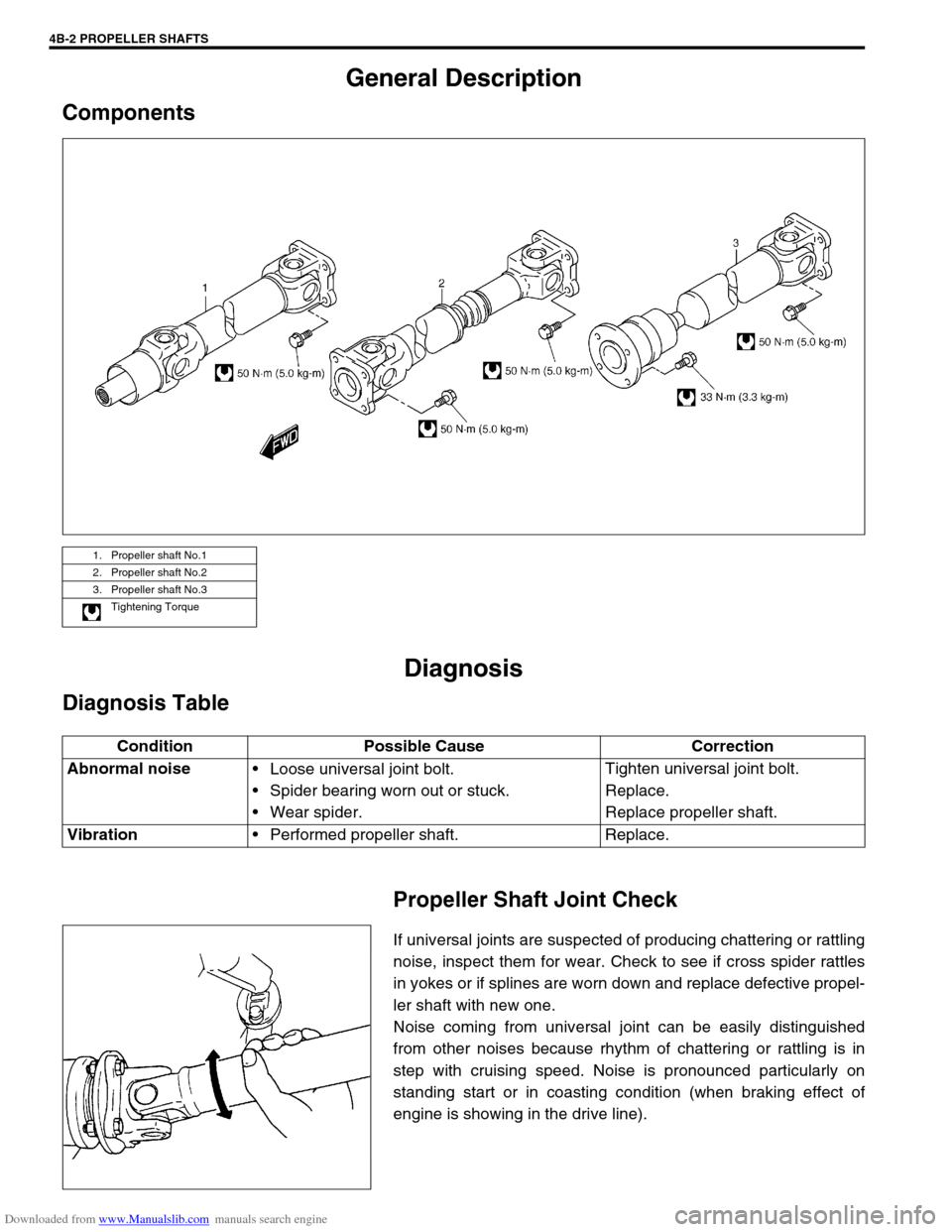
Components
Diagnosis
Diagnosis Table
Propeller Shaft Joint Check
If universal joints are suspected of producing chattering or rattling
noise, inspect them for wear. Check to see if cross spider rattles
in yokes or if splines are worn down and replace defective propel-
ler shaft with new one.
Noise coming from universal joint can be easily distinguished
from other noises because rhythm of chattering or rattling is in
step with cruising speed. Noise is pronounced particularly on
standing start or in coasting condition (when braking effect of
engine is showing in the drive line).
1. Propeller shaft No.1
2. Propeller shaft No.2
3. Propeller shaft No.3
Tightening Torque
Condition Possible Cause Correction
Abnormal noise
Loose universal joint bolt.
Spider bearing worn out or stuck.
Wear spider.Tighten universal joint bolt.
Replace.
Replace propeller shaft.
Vibration
Performed propeller shaft. Replace.
Page 256 of 687
Downloaded from www.Manualslib.com manuals search engine PROPELLER SHAFTS 4B-3
On-Vehicle Service
Propeller Shafts
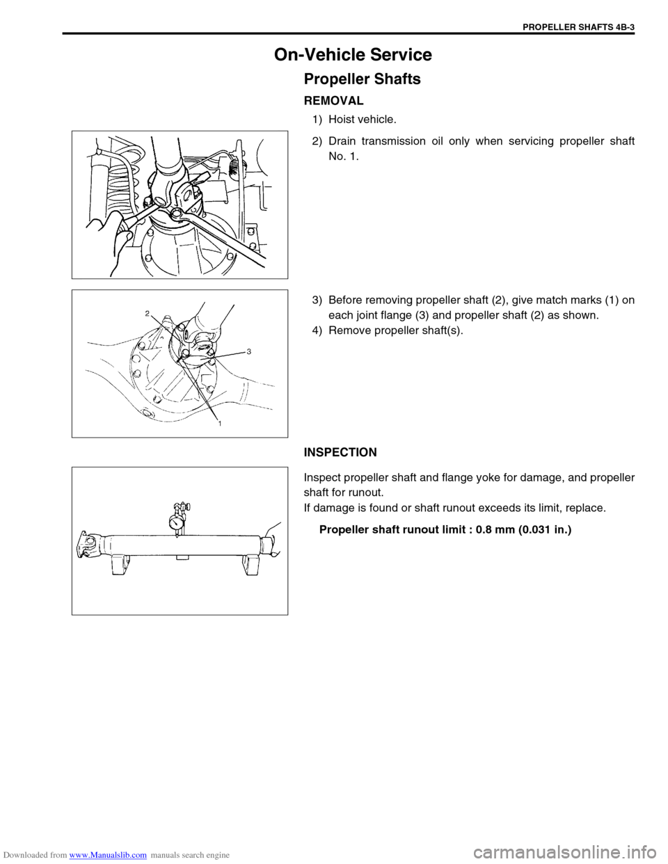
REMOVAL
1) Hoist vehicle.
2) Drain transmission oil only when servicing propeller shaft
No. 1.
3) Before removing propeller shaft (2), give match marks (1) on
each joint flange (3) and propeller shaft (2) as shown.
4) Remove propeller shaft(s).
INSPECTION
Inspect propeller shaft and flange yoke for damage, and propeller
shaft for runout.
If damage is found or shaft runout exceeds its limit, replace.
Propeller shaft runout limit : 0.8 mm (0.031 in.)
Page 257 of 687
Downloaded from www.Manualslib.com manuals search engine 4B-4 PROPELLER SHAFTS
INSTALLATION
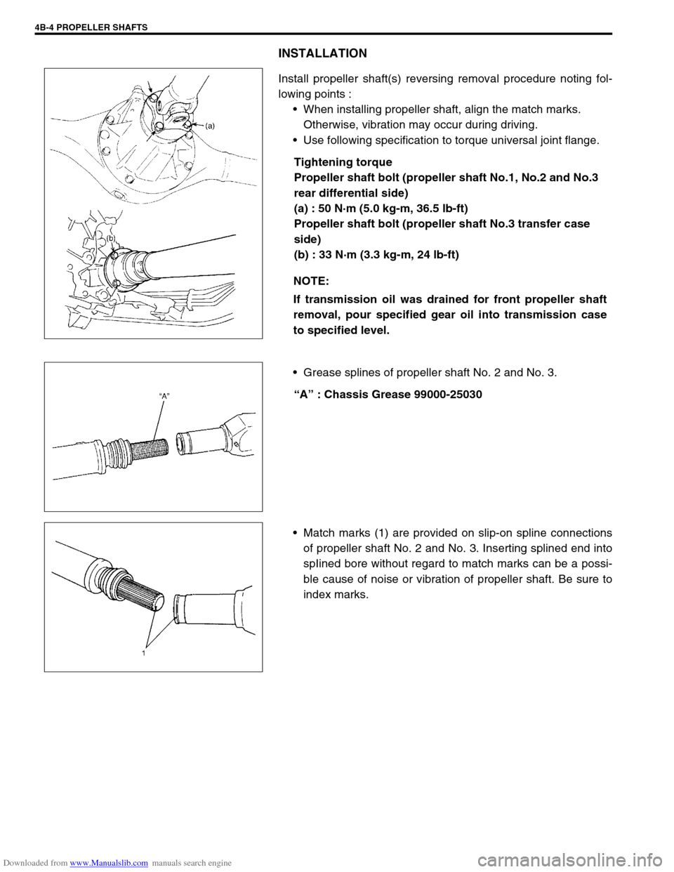
Install propeller shaft(s) reversing removal procedure noting fol-
lowing points :
When installing propeller shaft, align the match marks.
Otherwise, vibration may occur during driving.
Use following specification to torque universal joint flange.
Tightening torque
Propeller shaft bolt (propeller shaft No.1, No.2 and No.3
rear differential side)
(a) : 50 N·m (5.0 kg-m, 36.5 lb-ft)
Propeller shaft bolt (propeller shaft No.3 transfer case
side)
(b) : 33 N·m (3.3 kg-m, 24 lb-ft)
Grease splines of propeller shaft No. 2 and No. 3.
“A” : Chassis Grease 99000-25030
Match marks (1) are provided on slip-on spline connections
of propeller shaft No. 2 and No. 3. Inserting splined end into
spIined bore without regard to match marks can be a possi-
ble cause of noise or vibration of propeller shaft. Be sure to
index marks. NOTE:
If transmission oil was drained for front propeller shaft
removal, pour specified gear oil into transmission case
to specified level.
Page 258 of 687
Downloaded from www.Manualslib.com manuals search engine PROPELLER SHAFTS 4B-5
Universal Joint
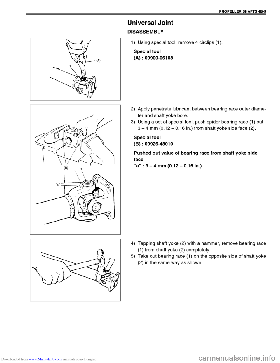
DISASSEMBLY
1) Using special tool, remove 4 circlips (1).
Special tool
(A) : 09900-06108
2) Apply penetrate lubricant between bearing race outer diame-
ter and shaft yoke bore.
3) Using a set of special tool, push spider bearing race (1) out
3 – 4 mm (0.12 – 0.16 in.) from shaft yoke side face (2).
Special tool
(B) : 09926-48010
Pushed out value of bearing race from shaft yoke side
face
“a” : 3 – 4 mm (0.12 – 0.16 in.)
4) Tapping shaft yoke (2) with a hammer, remove bearing race
(1) from shaft yoke (2) completely.
5) Take out bearing race (1) on the opposite side of shaft yoke
(2) in the same way as shown.
Page 259 of 687
Downloaded from www.Manualslib.com manuals search engine 4B-6 PROPELLER SHAFTS
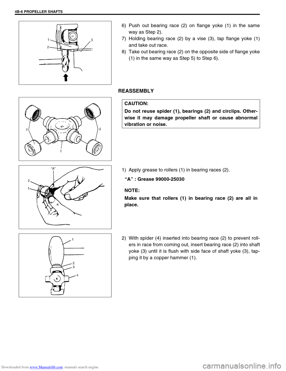
6) Push out bearing race (2) on flange yoke (1) in the same
way as Step 2).
7) Holding bearing race (2) by a vise (3), tap flange yoke (1)
and take out race.
8) Take out bearing race (2) on the opposite side of flange yoke
(1) in the same way as Step 5) to Step 6).
REASSEMBLY
1) Apply grease to rollers (1) in bearing races (2).
“A” : Grease 99000-25030
2) With spider (4) inserted into bearing race (2) to prevent roll-
ers in race from coming out, insert bearing race (2) into shaft
yoke (3) until it is flush with side face of shaft yoke (3), tap-
ping it by a copper hammer (1).
CAUTION:
Do not reuse spider (1), bearings (2) and circlips. Other-
wise it may damage propeller shaft or cause abnormal
vibration or noise.
NOTE:
Make sure that rollers (1) in bearing race (2) are all in
place.
Page 260 of 687
Downloaded from www.Manualslib.com manuals search engine PROPELLER SHAFTS 4B-7
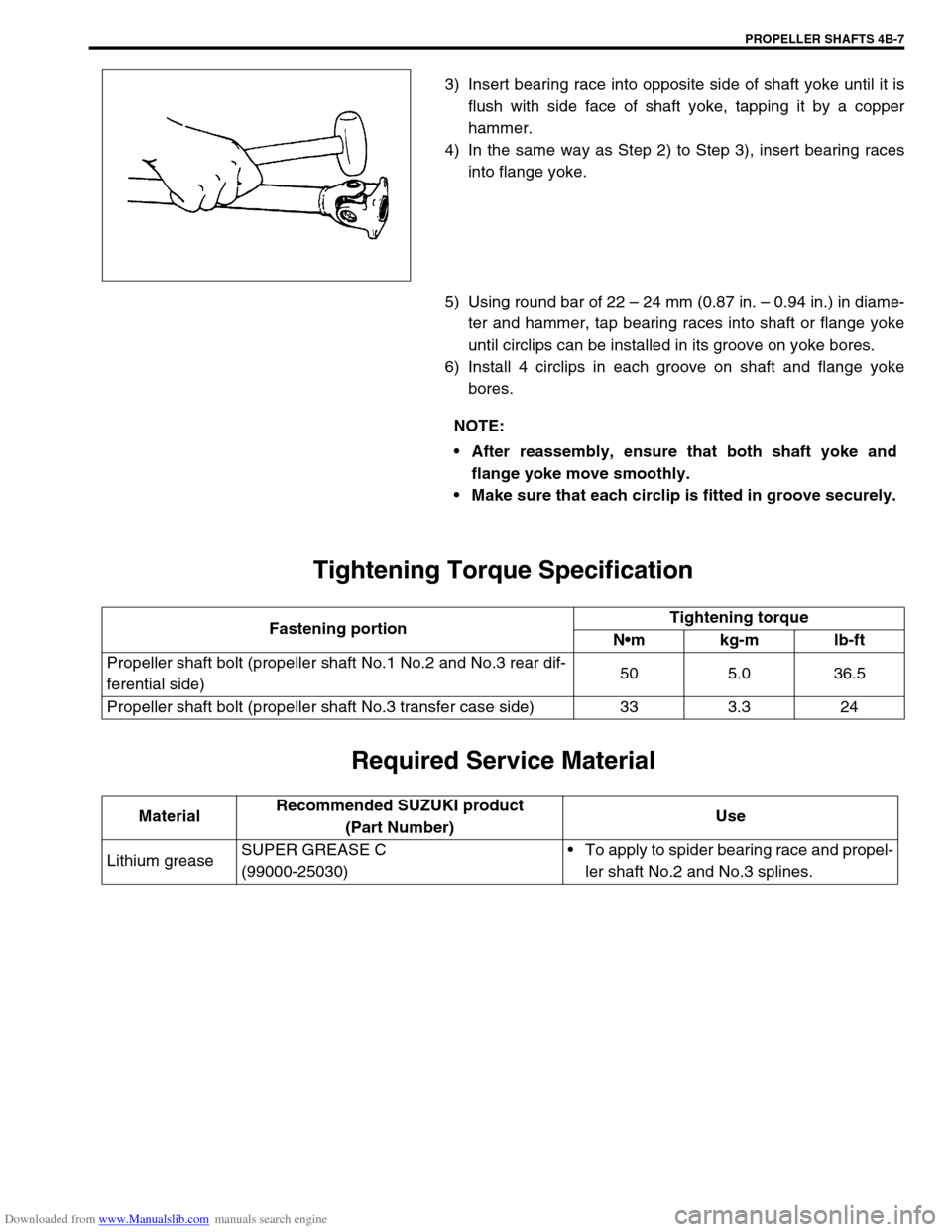
3) Insert bearing race into opposite side of shaft yoke until it is
flush with side face of shaft yoke, tapping it by a copper
hammer.
4) In the same way as Step 2) to Step 3), insert bearing races
into flange yoke.
5) Using round bar of 22 – 24 mm (0.87 in. – 0.94 in.) in diame-
ter and hammer, tap bearing races into shaft or flange yoke
until circlips can be installed in its groove on yoke bores.
6) Install 4 circlips in each groove on shaft and flange yoke
bores.
Tightening Torque Specification
Required Service Material
NOTE:
After reassembly, ensure that both shaft yoke and
flange yoke move smoothly.
Make sure that each circlip is fitted in groove securely.
Fastening portionTightening torque
Nm kg-m lb-ft
Propeller shaft bolt (propeller shaft No.1 No.2 and No.3 rear dif-
ferential side)50 5.0 36.5
Propeller shaft bolt (propeller shaft No.3 transfer case side) 33 3.3 24
MaterialRecommended SUZUKI product
(Part Number)Use
Lithium greaseSUPER GREASE C
(99000-25030)To apply to spider bearing race and propel-
ler shaft No.2 and No.3 splines.