SUZUKI SWIFT 2000 1.G RG413 Service Workshop Manual
[x] Cancel search | Manufacturer: SUZUKI, Model Year: 2000, Model line: SWIFT, Model: SUZUKI SWIFT 2000 1.GPages: 698, PDF Size: 16.01 MB
Page 131 of 698
3B-10 MANUAL RACK AND PINION
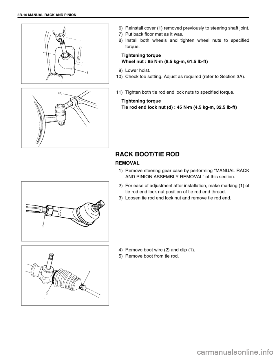
6) Reinstall cover (1) removed previously to steering shaft joint.
7) Put back floor mat as it was.
8) Install both wheels and tighten wheel nuts to specified
torque.
Tightening torque
Wheel nut : 85 N·m (8.5 kg-m, 61.5 lb-ft)
9) Lower hoist.
10) Check toe setting. Adjust as required (refer to Section 3A).
11) Tighten both tie rod end lock nuts to specified torque.
Tightening torque
Tie rod end lock nut (d) : 45 N·m (4.5 kg-m, 32.5 lb-ft)
RACK BOOT/TIE ROD
REMOVAL
1) Remove steering gear case by performing “MANUAL RACK
AND PINION ASSEMBLY REMOVAL” of this section.
2) For ease of adjustment after installation, make marking (1) of
tie rod end lock nut position of tie rod end thread.
3) Loosen tie rod end lock nut and remove tie rod end.
4) Remove boot wire (2) and clip (1).
5) Remove boot from tie rod.
Page 132 of 698
MANUAL RACK AND PINION 3B-11
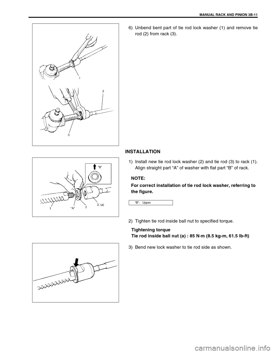
6) Unbend bent part of tie rod lock washer (1) and remove tie
rod (2) from rack (3).
INSTALLATION
1) Install new tie rod lock washer (2) and tie rod (3) to rack (1).
Align straight part “A” of washer with flat part “B” of rack.
2) Tighten tie rod inside ball nut to specified torque.
Tightening torque
Tie rod inside ball nut (a) : 85 N·m (8.5 kg-m, 61.5 lb-ft)
3) Bend new lock washer to tie rod side as shown.
NOTE:
For correct installation of tie rod lock washer, referring to
the figure.
“B”: Upper
Page 133 of 698
3B-12 MANUAL RACK AND PINION
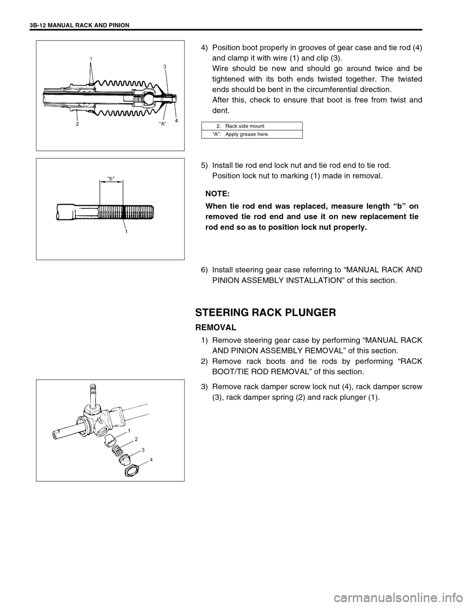
4) Position boot properly in grooves of gear case and tie rod (4)
and clamp it with wire (1) and clip (3).
Wire should be new and should go around twice and be
tightened with its both ends twisted together. The twisted
ends should be bent in the circumferential direction.
After this, check to ensure that boot is free from twist and
dent.
5) Install tie rod end lock nut and tie rod end to tie rod.
Position lock nut to marking (1) made in removal.
6) Install steering gear case referring to “MANUAL RACK AND
PINION ASSEMBLY INSTALLATION” of this section.
STEERING RACK PLUNGER
REMOVAL
1) Remove steering gear case by performing “MANUAL RACK
AND PINION ASSEMBLY REMOVAL” of this section.
2) Remove rack boots and tie rods by performing “RACK
BOOT/TIE ROD REMOVAL” of this section.
3) Remove rack damper screw lock nut (4), rack damper screw
(3), rack damper spring (2) and rack plunger (1).
2. Rack side mount
“A”: Apply grease here.
NOTE:
When tie rod end was replaced, measure length “b” on
removed tie rod end and use it on new replacement tie
rod end so as to position lock nut properly.
Page 134 of 698
MANUAL RACK AND PINION 3B-13
INSPECTION
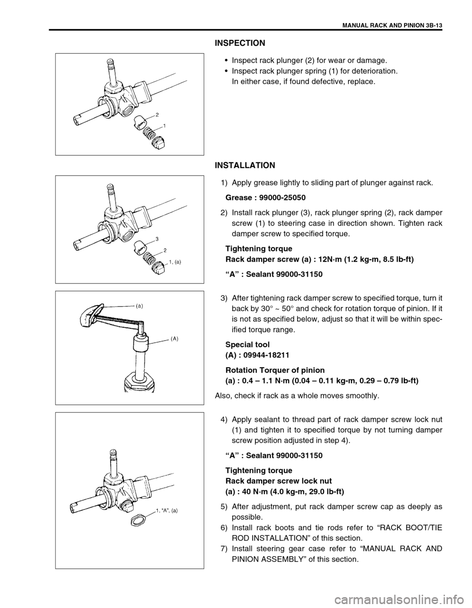
Inspect rack plunger (2) for wear or damage.
Inspect rack plunger spring (1) for deterioration.
In either case, if found defective, replace.
INSTALLATION
1) Apply grease lightly to sliding part of plunger against rack.
Grease : 99000-25050
2) Install rack plunger (3), rack plunger spring (2), rack damper
screw (1) to steering case in direction shown. Tighten rack
damper screw to specified torque.
Tightening torque
Rack damper screw (a) : 12N·m (1.2 kg-m, 8.5 lb-ft)
“A” : Sealant 99000-31150
3) After tightening rack damper screw to specified torque, turn it
back by 30° ~ 50° and check for rotation torque of pinion. If it
is not as specified below, adjust so that it will be within spec-
ified torque range.
Special tool
(A) : 09944-18211
Rotation Torquer of pinion
(a) : 0.4 – 1.1 N·m (0.04 – 0.11 kg-m, 0.29 – 0.79 lb-ft)
Also, check if rack as a whole moves smoothly.
4) Apply sealant to thread part of rack damper screw lock nut
(1) and tighten it to specified torque by not turning damper
screw position adjusted in step 4).
“A” : Sealant 99000-31150
Tightening torque
Rack damper screw lock nut
(a) : 40 N·m (4.0 kg-m, 29.0 lb-ft)
5) After adjustment, put rack damper screw cap as deeply as
possible.
6) Install rack boots and tie rods refer to “RACK BOOT/TIE
ROD INSTALLATION” of this section.
7) Install steering gear case refer to “MANUAL RACK AND
PINION ASSEMBLY” of this section.
Page 135 of 698
3B-14 MANUAL RACK AND PINION
STEERING PINION
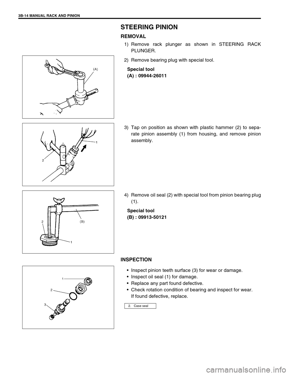
REMOVAL
1) Remove rack plunger as shown in STEERING RACK
PLUNGER.
2) Remove bearing plug with special tool.
Special tool
(A) : 09944-26011
3) Tap on position as shown with plastic hammer (2) to sepa-
rate pinion assembly (1) from housing, and remove pinion
assembly.
4) Remove oil seal (2) with special tool from pinion bearing plug
(1).
Special tool
(B) : 09913-50121
INSPECTION
Inspect pinion teeth surface (3) for wear or damage.
Inspect oil seal (1) for damage.
Replace any part found defective.
Check rotation condition of bearing and inspect for wear.
If found defective, replace.
2. Case seal
Page 136 of 698
MANUAL RACK AND PINION 3B-15
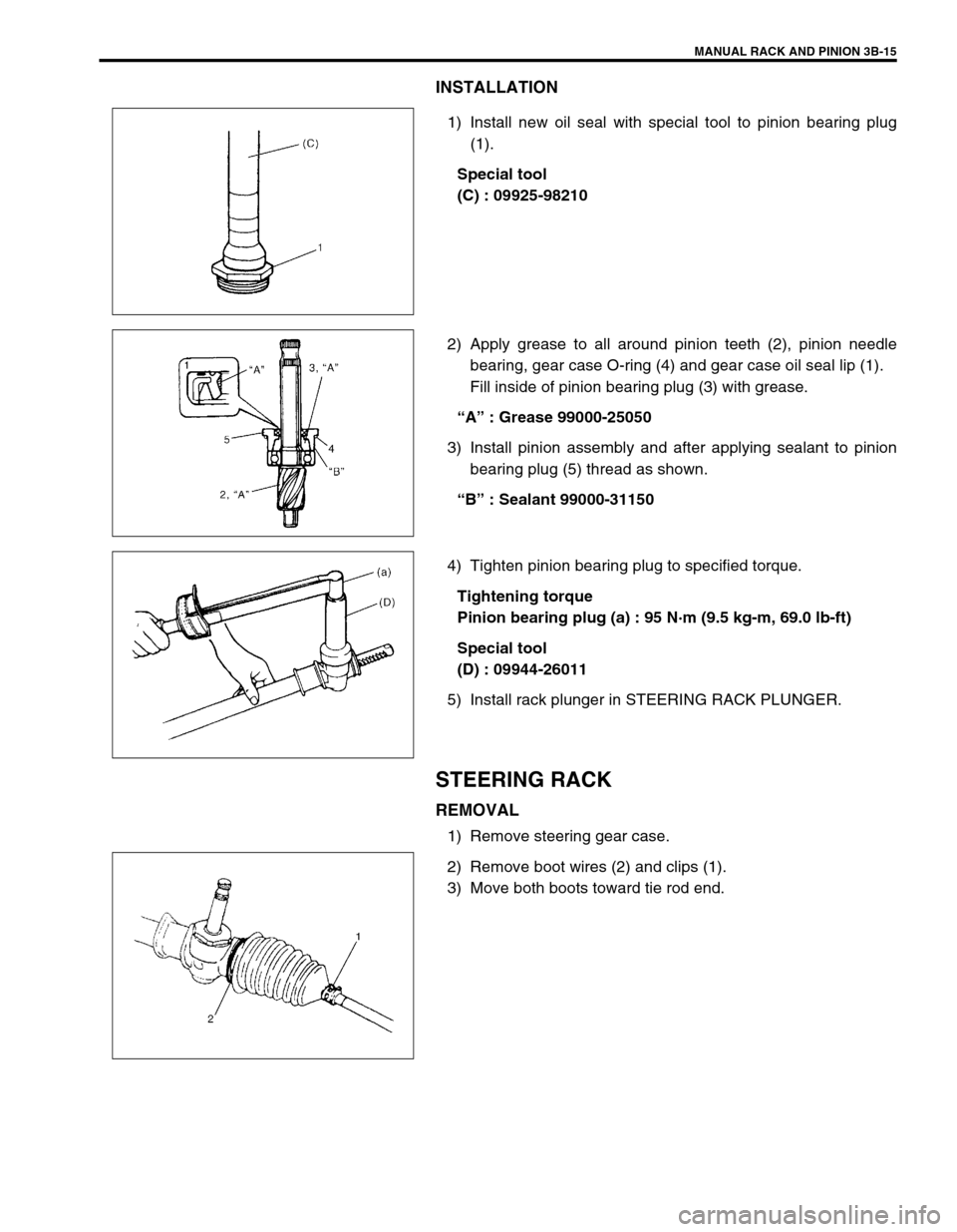
INSTALLATION
1) Install new oil seal with special tool to pinion bearing plug
(1).
Special tool
(C) : 09925-98210
2) Apply grease to all around pinion teeth (2), pinion needle
bearing, gear case O-ring (4) and gear case oil seal lip (1).
Fill inside of pinion bearing plug (3) with grease.
“A” : Grease 99000-25050
3) Install pinion assembly and after applying sealant to pinion
bearing plug (5) thread as shown.
“B” : Sealant 99000-31150
4) Tighten pinion bearing plug to specified torque.
Tightening torque
Pinion bearing plug (a) : 95 N·m (9.5 kg-m, 69.0 lb-ft)
Special tool
(D) : 09944-26011
5) Install rack plunger in STEERING RACK PLUNGER.
STEERING RACK
REMOVAL
1) Remove steering gear case.
2) Remove boot wires (2) and clips (1).
3) Move both boots toward tie rod end.
Page 137 of 698
3B-16 MANUAL RACK AND PINION
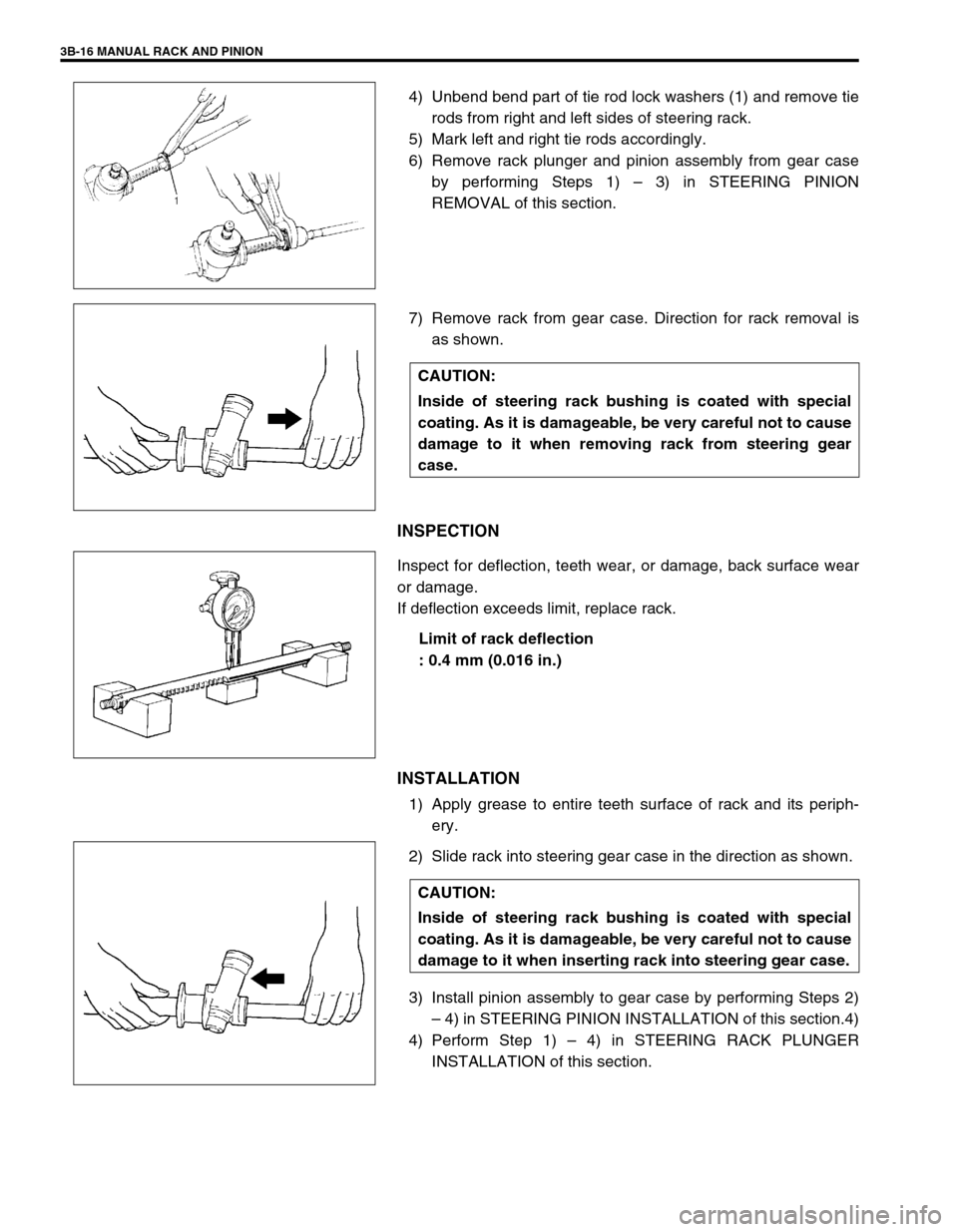
4) Unbend bend part of tie rod lock washers (1) and remove tie
rods from right and left sides of steering rack.
5) Mark left and right tie rods accordingly.
6) Remove rack plunger and pinion assembly from gear case
by performing Steps 1) – 3) in STEERING PINION
REMOVAL of this section.
7) Remove rack from gear case. Direction for rack removal is
as shown.
INSPECTION
Inspect for deflection, teeth wear, or damage, back surface wear
or damage.
If deflection exceeds limit, replace rack.
Limit of rack deflection
: 0.4 mm (0.016 in.)
INSTALLATION
1) Apply grease to entire teeth surface of rack and its periph-
ery.
2) Slide rack into steering gear case in the direction as shown.
3) Install pinion assembly to gear case by performing Steps 2)
– 4) in STEERING PINION INSTALLATION of this section.4)
4) Perform Step 1) – 4) in STEERING RACK PLUNGER
INSTALLATION of this section.
CAUTION:
Inside of steering rack bushing is coated with special
coating. As it is damageable, be very careful not to cause
damage to it when removing rack from steering gear
case.
CAUTION:
Inside of steering rack bushing is coated with special
coating. As it is damageable, be very careful not to cause
damage to it when inserting rack into steering gear case.
Page 138 of 698
MANUAL RACK AND PINION 3B-17
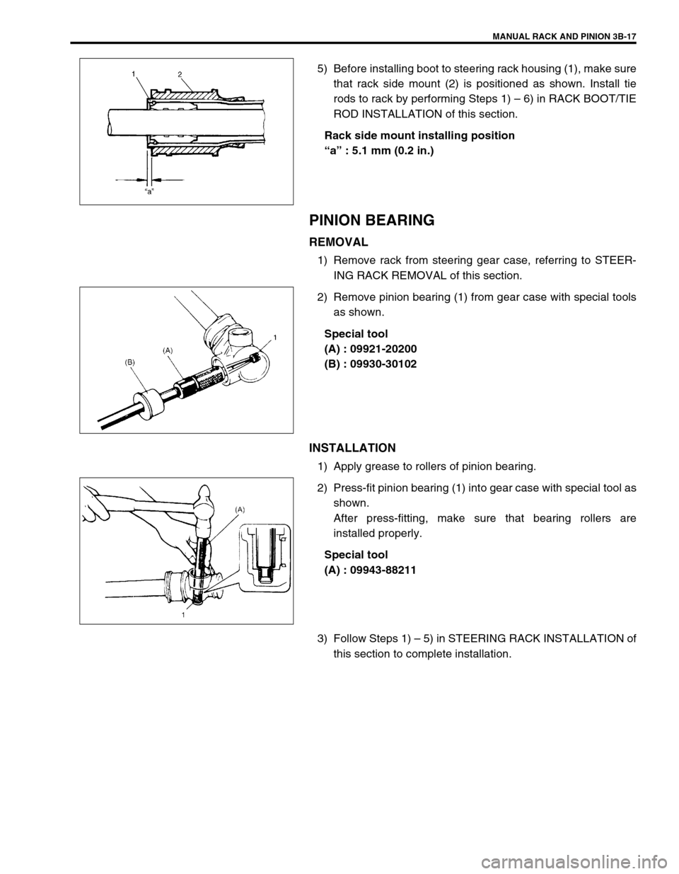
5) Before installing boot to steering rack housing (1), make sure
that rack side mount (2) is positioned as shown. Install tie
rods to rack by performing Steps 1) – 6) in RACK BOOT/TIE
ROD INSTALLATION of this section.
Rack side mount installing position
“a” : 5.1 mm (0.2 in.)
PINION BEARING
REMOVAL
1) Remove rack from steering gear case, referring to STEER-
ING RACK REMOVAL of this section.
2) Remove pinion bearing (1) from gear case with special tools
as shown.
Special tool
(A) : 09921-20200
(B) : 09930-30102
INSTALLATION
1) Apply grease to rollers of pinion bearing.
2) Press-fit pinion bearing (1) into gear case with special tool as
shown.
After press-fitting, make sure that bearing rollers are
installed properly.
Special tool
(A) : 09943-88211
3) Follow Steps 1) – 5) in STEERING RACK INSTALLATION of
this section to complete installation.
Page 139 of 698
3B-18 MANUAL RACK AND PINION
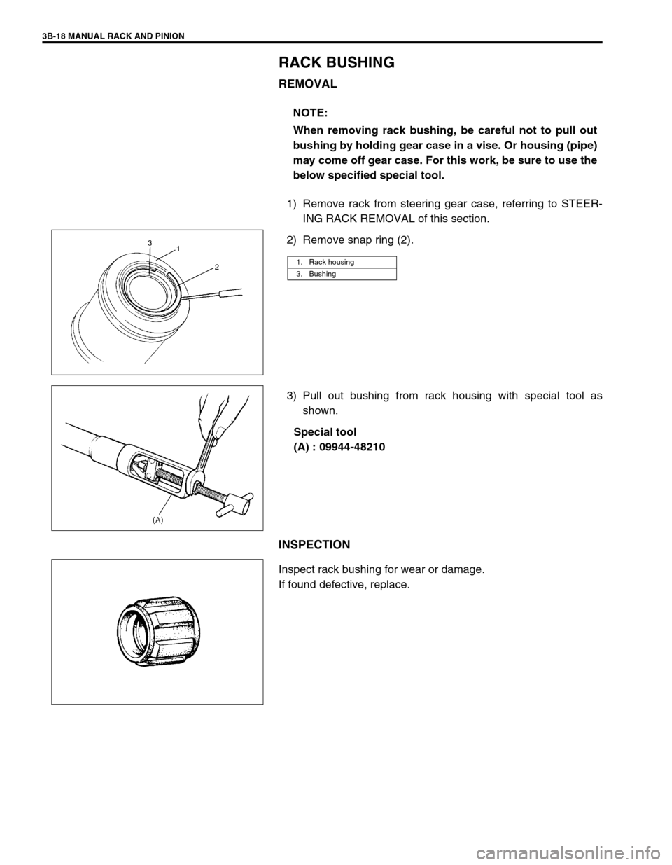
RACK BUSHING
REMOVAL
1) Remove rack from steering gear case, referring to STEER-
ING RACK REMOVAL of this section.
2) Remove snap ring (2).
3) Pull out bushing from rack housing with special tool as
shown.
Special tool
(A) : 09944-48210
INSPECTION
Inspect rack bushing for wear or damage.
If found defective, replace.NOTE:
When removing rack bushing, be careful not to pull out
bushing by holding gear case in a vise. Or housing (pipe)
may come off gear case. For this work, be sure to use the
below specified special tool.
1. Rack housing
3. Bushing
Page 140 of 698
MANUAL RACK AND PINION 3B-19
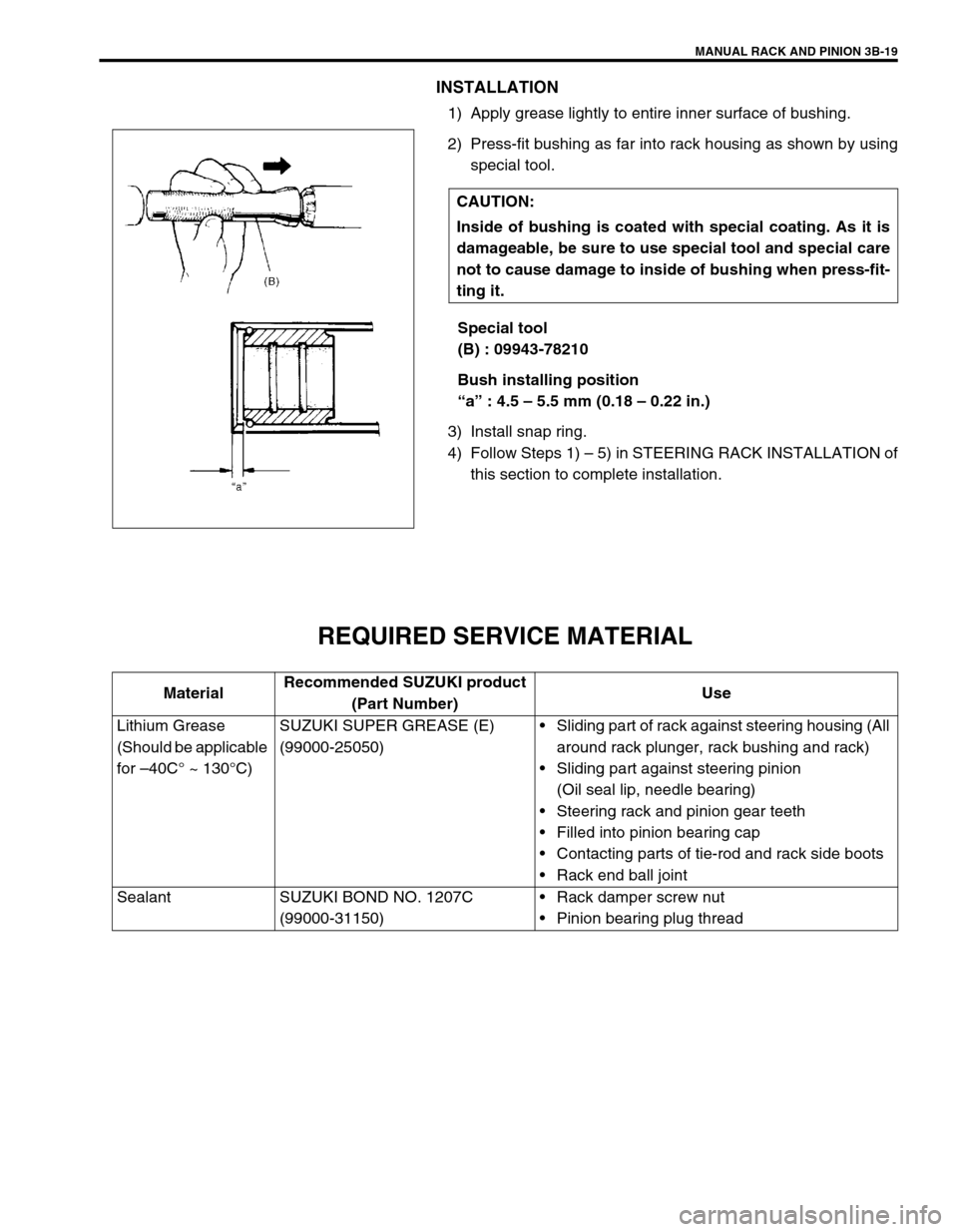
INSTALLATION
1) Apply grease lightly to entire inner surface of bushing.
2) Press-fit bushing as far into rack housing as shown by using
special tool.
Special tool
(B) : 09943-78210
Bush installing position
“a” : 4.5 – 5.5 mm (0.18 – 0.22 in.)
3) Install snap ring.
4) Follow Steps 1) – 5) in STEERING RACK INSTALLATION of
this section to complete installation.
REQUIRED SERVICE MATERIAL
CAUTION:
Inside of bushing is coated with special coating. As it is
damageable, be sure to use special tool and special care
not to cause damage to inside of bushing when press-fit-
ting it.
MaterialRecommended SUZUKI product
(Part Number)Use
Lithium Grease
(Should be applicable
for –40C° ~ 130°C)SUZUKI SUPER GREASE (E)
(99000-25050)Sliding part of rack against steering housing (All
around rack plunger, rack bushing and rack)
Sliding part against steering pinion
(Oil seal lip, needle bearing)
Steering rack and pinion gear teeth
Filled into pinion bearing cap
Contacting parts of tie-rod and rack side boots
Rack end ball joint
Sealant SUZUKI BOND NO. 1207C
(99000-31150)Rack damper screw nut
Pinion bearing plug thread