Torque SUZUKI SWIFT 2000 1.G RG413 Service Workshop Manual
[x] Cancel search | Manufacturer: SUZUKI, Model Year: 2000, Model line: SWIFT, Model: SUZUKI SWIFT 2000 1.GPages: 698, PDF Size: 16.01 MB
Page 662 of 698

ENGINE AND EMISSION CONTROL SYSTEM 6E1-41
TIGHTENING TORQUE SPECIFICATION
09931-76030
16/14 pin DLC cable
NOTE:
“A”: This kit includes the following items.
1. Tool body & washer, 2. Body plug, 3. Body attachment-1, 4. Holder, 5. Return hose & clamp,
6. Body attachment-2 & washer, 7. Hose attachment-1, 8. Hose attachment-2
“B”: This kit includes the following items.
1. Storage case, 2. Operator’s manual, 3. Tech 1A, 4. DLC cable (14/26 pin, 09931-76040),
5. Test lead/probe, 6. Power source cable, 7. DLC cable adaptor, 8. Self-test adaptor
Fastening partTightening torque
Nm kg-m lb-ft
TP sensor mounting screw 2.5 0.25 1.8
IAC valve 3.5 0.35 2.5
ECT sensor 15 1.5 11.5
Heated oxygen sensor-1 and -2 45 4.5 32.5
Camshaft position sensor 10 1.0 7.5
Page 669 of 698
IGNITION SYSTEM (ELECTRONIC IGNITION SYSTEM 6F1-7
6) Install spark plugs and torque them to specification.
Tightening torque
Spark plug : 25 N·m (2.5 kg-m, 18.0 lb-ft)
7) Install ignition coil assemblies referring to IGNITION COIL
ASSEMBLY in this section.
8) Install high-tension cords securely by gripping their caps.
9) Install cylinder head upper cover and air intake pipe.
IGNITION COIL ASSEMBLY
(INCLUDING IGNITOR)
Inspection
1) Disconnect negative cable at battery.
2) Remove air intake pipe and cylinder head upper cover.
3) Disconnect ignition coil coupler.
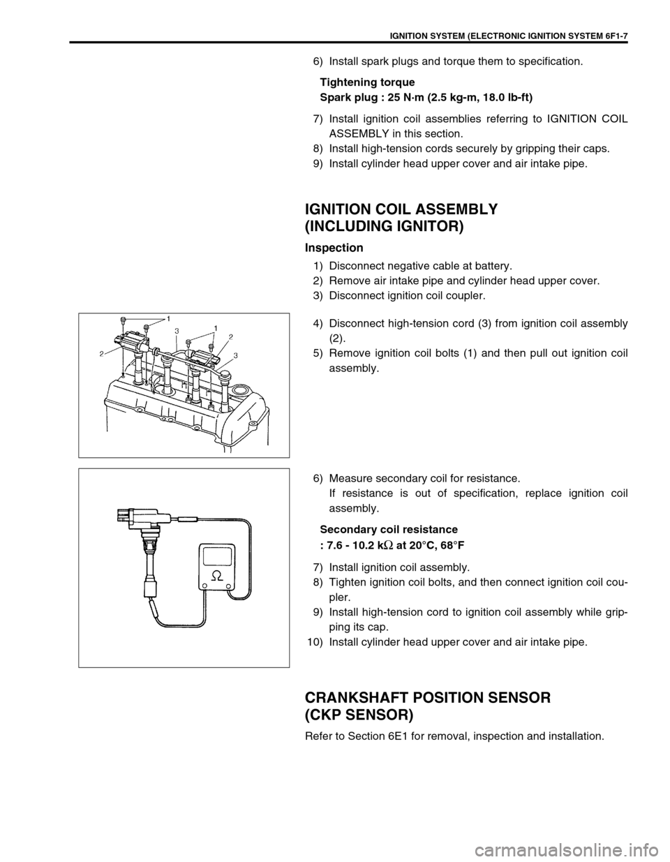
4) Disconnect high-tension cord (3) from ignition coil assembly
(2).
5) Remove ignition coil bolts (1) and then pull out ignition coil
assembly.
6) Measure secondary coil for resistance.
If resistance is out of specification, replace ignition coil
assembly.
Secondary coil resistance
: 7.6 - 10.2 k
Ω at 20°C, 68°F
7) Install ignition coil assembly.
8) Tighten ignition coil bolts, and then connect ignition coil cou-
pler.
9) Install high-tension cord to ignition coil assembly while grip-
ping its cap.
10) Install cylinder head upper cover and air intake pipe.
CRANKSHAFT POSITION SENSOR
(CKP SENSOR)
Refer to Section 6E1 for removal, inspection and installation.
Page 675 of 698
CRANKING SYSTEM 6G-3
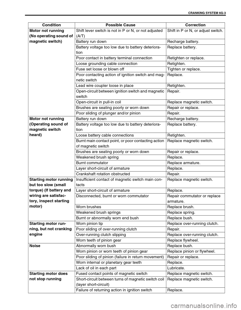
Condition Possible Cause Correction
Motor not running
(No operating sound of
magnetic switch)Shift lever switch is not in P or N, or not adjusted
(A/T)Shift in P or N, or adjust switch.
Battery run down Recharge battery.
Battery voltage too low due to battery deteriora-
tionReplace battery.
Poor contact in battery terminal connection Retighten or replace.
Loose grounding cable connection Retighten.
Fuse set loose or blown off Tighten or replace.
Poor contacting action of ignition switch and mag-
netic switchReplace.
Lead wire coupler loose in place Retighten.
Open-circuit between ignition switch and magnetic
switchRepair.
Open-circuit in pull-in coil Replace magnetic switch.
Brushes are seating poorly or worn down Repair or replace.
Poor sliding of plunger and/or pinion Repair.
Motor not running
(Operating sound of
magnetic switch
heard)Battery run down Recharge battery.
Battery voltage too low due to battery deteriora-
tionReplace battery.
Loose battery cable connections Retighten.
Burnt main contact point, or poor contacting action
of magnetic switchReplace magnetic switch.
Brushes are seating poorly or worn down Repair or replace.
Weakened brush spring Replace.
Burnt commutator Replace armature.
Layer short-circuit of armature Replace.
Crankshaft rotation obstructed Repair.
Starting motor running
but too slow (small
torque) (If battery and
wiring are satisfac-
tory, inspect starting
motor)Insufficient contact of magnetic switch main con-
tactsReplace magnetic switch.
Layer short-circuit of armature Replace.
Disconnected, burnt or worn commutator Repair commutator or replace
armature.
Worn brushes Replace brush.
Weakened brush springs Replace spring.
Burnt or abnormally worn end bush Replace bush.
Starting motor run-
ning, but not cranking
engineWorn pinion tip Replace over-running clutch.
Poor sliding of over-running clutch Repair.
Over-running clutch slipping Replace over-running clutch.
Worn teeth of pinion gear Replace flywheel.
Noise
Abnormally worn bush Replace bush.
Worn pinion or worn teeth of pinion gear Replace pinion or flywheel.
Poor sliding of pinion (failure in return movement) Repair or replace.
Worn internal or planetary gear teeth Replace.
Lack of oil in each part Lubricate.
Starting motor does
not stop runningFused contact points of magnetic switch Replace magnetic switch.
Short-circuit between turns of magnetic switch coil
(layer short-circuit)Replace magnetic switch.
Failure of returning action in ignition switch Replace.
Page 677 of 698
CRANKING SYSTEM 6G-5
NO-LOAD PERFORMANCE TEST
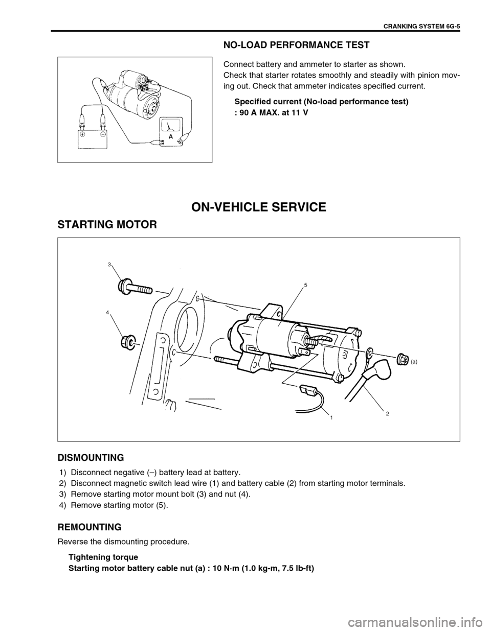
Connect battery and ammeter to starter as shown.
Check that starter rotates smoothly and steadily with pinion mov-
ing out. Check that ammeter indicates specified current.
Specified current (No-load performance test)
: 90 A MAX. at 11 V
ON-VEHICLE SERVICE
STARTING MOTOR
DISMOUNTING
1) Disconnect negative (–) battery lead at battery.
2) Disconnect magnetic switch lead wire (1) and battery cable (2) from starting motor terminals.
3) Remove starting motor mount bolt (3) and nut (4).
4) Remove starting motor (5).
REMOUNTING
Reverse the dismounting procedure.
Tightening torque
Starting motor battery cable nut (a) : 10 N·m (1.0 kg-m, 7.5 lb-ft)
Page 681 of 698
CHARGING SYSTEM 6H-1
6F1
6F2
6G
6K
7A
6H
7B1
7C1
7D
7E
7F
8A
8B
8C
8D
8E
9
10
10A
10B
SECTION 6H
CHARGING SYSTEM
CONTENTS
GENERAL DESCRIPTION .............................. 6H-2
BATTERY ..................................................... 6H-2
CARRIER AND HOLD-DOWN ................. 6H-2
ELECTROLYTE FREEZING .................... 6H-2
SULFATION ............................................. 6H-2
BUILT-IN INDICATOR (IF EQUIPPED) ... 6H-2
CARE OF BATTERY ................................ 6H-3
GENERATOR .............................................. 6H-4
DIAGNOSIS ..................................................... 6H-5
BATTERY ..................................................... 6H-5
VISUAL INSPECTION.............................. 6H-5
HYDROMETER TEST.............................. 6H-5
GENERATOR .............................................. 6H-6
CHARGING INDICATOR LAMP
OPERATION ............................................ 6H-6
UNDERCHARGED BATTERY ................. 6H-7
OVERCHARGED BATTERY.................... 6H-8ON-VEHICLE SERVICE .................................. 6H-9
BATTERY .................................................... 6H-9
JUMP STARTING IN CASE OF
EMERGENCY .......................................... 6H-9
DISMOUNTING...................................... 6H-10
HANDLING............................................. 6H-10
REMOUNTING....................................... 6H-10
GENERATOR ............................................ 6H-10
GENERATOR BELT .............................. 6H-10
DISMOUNTING AND REMOUNTING ... 6H-11
DISASSEMBLY AND REASSEMBLY .... 6H-11
INSPECTION ......................................... 6H-12
SPECIFICATION ........................................... 6H-14
BATTERY .................................................. 6H-14
GENERATOR ............................................ 6H-14
TIGHTENING TORQUE SPECIFICATION.... 6H-14
WARNING:
For vehicles equipped with Supplemental Restraint (Air Bag) System:
Service on and around the air bag system components or wiring must be performed only by an
authorized SUZUKI dealer. Refer to “Air Bag System Components and Wiring Location View” under
“General Description” in air bag system section in order to confirm whether you are performing ser-
vice on or near the air bag system components or wiring. Please observe all WARNINGS and “Ser-
vice Precautions” under “On-Vehicle Service” in air bag system section before performing service
on or around the air bag system components or wiring. Failure to follow WARNINGS could result in
unintentional activation of the system or could render the system inoperative. Either of these two
conditions may result in severe injury.
Technical service work must be started at least 90 seconds after the ignition switch is turned to the
“LOCK” position and the negative cable is disconnected from the battery. Otherwise, the system
may be activated by reserve energy in the Sensing and Diagnostic Module (SDM).
Page 690 of 698
6H-10 CHARGING SYSTEM
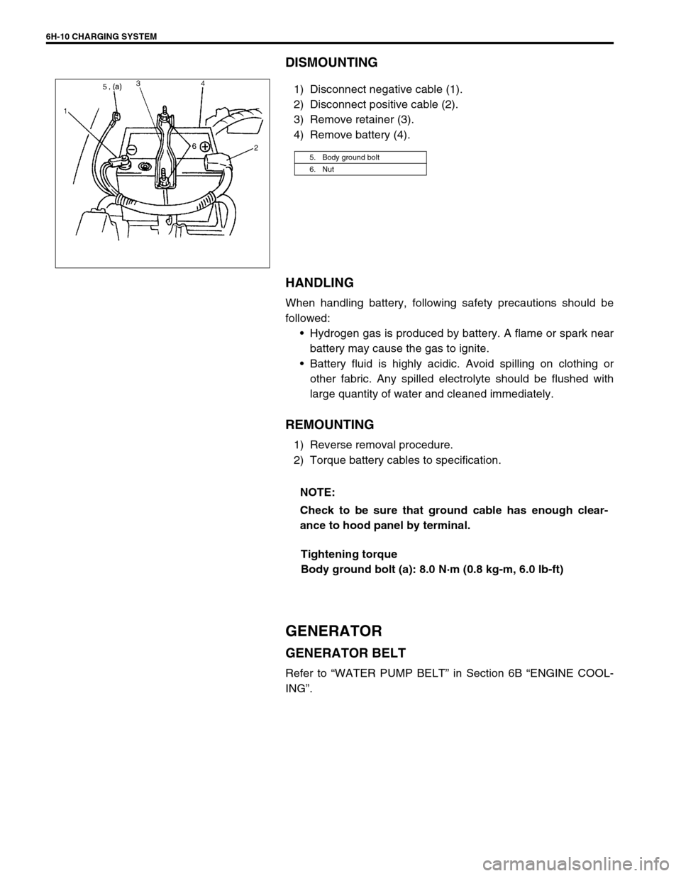
DISMOUNTING
1) Disconnect negative cable (1).
2) Disconnect positive cable (2).
3) Remove retainer (3).
4) Remove battery (4).
HANDLING
When handling battery, following safety precautions should be
followed:
Hydrogen gas is produced by battery. A flame or spark near
battery may cause the gas to ignite.
Battery fluid is highly acidic. Avoid spilling on clothing or
other fabric. Any spilled electrolyte should be flushed with
large quantity of water and cleaned immediately.
REMOUNTING
1) Reverse removal procedure.
2) Torque battery cables to specification.
Tightening torque
Body ground bolt (a): 8.0 N·m (0.8 kg-m, 6.0 lb-ft)
GENERATOR
GENERATOR BELT
Refer to “WATER PUMP BELT” in Section 6B “ENGINE COOL-
ING”.
5. Body ground bolt
6. Nut
NOTE:
Check to be sure that ground cable has enough clear-
ance to hood panel by terminal.
Page 691 of 698
CHARGING SYSTEM 6H-11
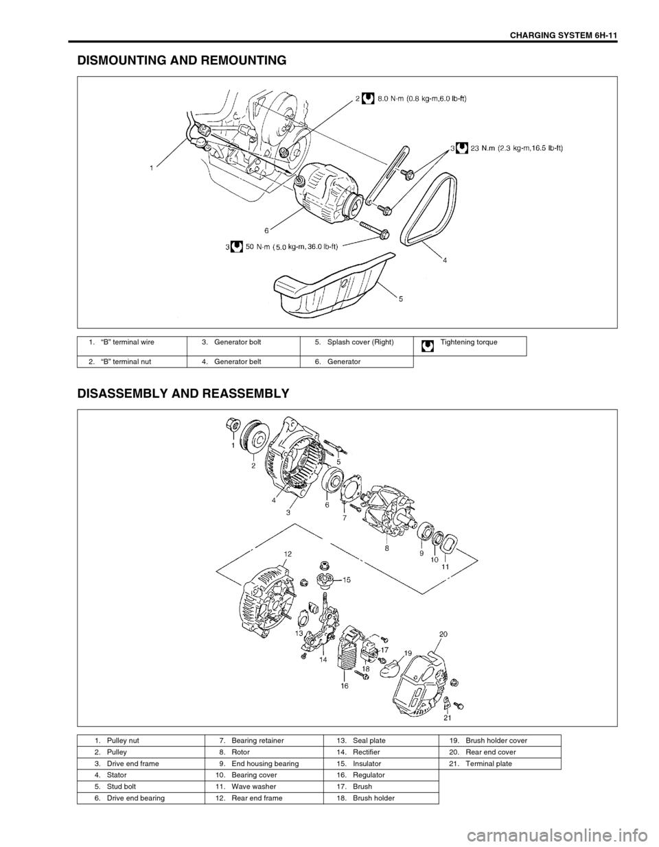
DISMOUNTING AND REMOUNTING
DISASSEMBLY AND REASSEMBLY
1.“B” terminal wire 3. Generator bolt 5. Splash cover (Right) Tightening torque
2.“B” terminal nut 4. Generator belt 6. Generator
1. Pulley nut 7. Bearing retainer 13. Seal plate 19. Brush holder cover
2. Pulley 8. Rotor 14. Rectifier 20. Rear end cover
3. Drive end frame 9. End housing bearing 15. Insulator 21. Terminal plate
4. Stator 10. Bearing cover 16. Regulator
5. Stud bolt 11. Wave washer 17. Brush
6. Drive end bearing 12. Rear end frame 18. Brush holder
Page 694 of 698
6H-14 CHARGING SYSTEM
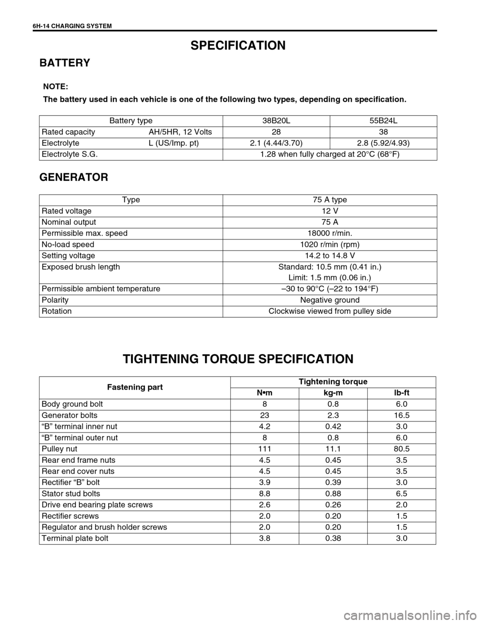
SPECIFICATION
BATTERY
GENERATOR
TIGHTENING TORQUE SPECIFICATION
NOTE:
The battery used in each vehicle is one of the following two types, depending on specification.
Battery type 38B20L 55B24L
Rated capacity AH/5HR, 12 Volts 28 38
Electrolyte L (US/Imp. pt) 2.1 (4.44/3.70) 2.8 (5.92/4.93)
Electrolyte S.G. 1.28 when fully charged at 20°C (68°F)
Type 75 A type
Rated voltage 12 V
Nominal output 75 A
Permissible max. speed 18000 r/min.
No-load speed 1020 r/min (rpm)
Setting voltage 14.2 to 14.8 V
Exposed brush length Standard: 10.5 mm (0.41 in.)
Limit: 1.5 mm (0.06 in.)
Permissible ambient temperature–30 to 90°C (–22 to 194°F)
Polarity Negative ground
Rotation Clockwise viewed from pulley side
Fastening partTightening torque
Nm kg-m lb-ft
Body ground bolt 8 0.8 6.0
Generator bolts 23 2.3 16.5
“B” terminal inner nut 4.2 0.42 3.0
“B” terminal outer nut 8 0.8 6.0
Pulley nut 111 11.1 80.5
Rear end frame nuts 4.5 0.45 3.5
Rear end cover nuts 4.5 0.45 3.5
Rectifier “B” bolt 3.9 0.39 3.0
Stator stud bolts 8.8 0.88 6.5
Drive end bearing plate screws 2.6 0.26 2.0
Rectifier screws 2.0 0.20 1.5
Regulator and brush holder screws 2.0 0.20 1.5
Terminal plate bolt 3.8 0.38 3.0
Page 696 of 698
6K-2 EXHAUST SYSTEM
GENERAL DESCRIPTION
The exhaust system consists of an exhaust manifold, three-way catalytic converter (TWC) in catalyst case,
exhaust pipes, a muffler and seals, gasket and etc.
The three-way catalytic converter is an emission control device added to the exhaust system to lower the levels
of Hydrocarbon (HC), Carbon Monoxide (CO), and Oxides of Nitrogen (NOx) pollutants in the exhaust gas.
MAINTENANCE
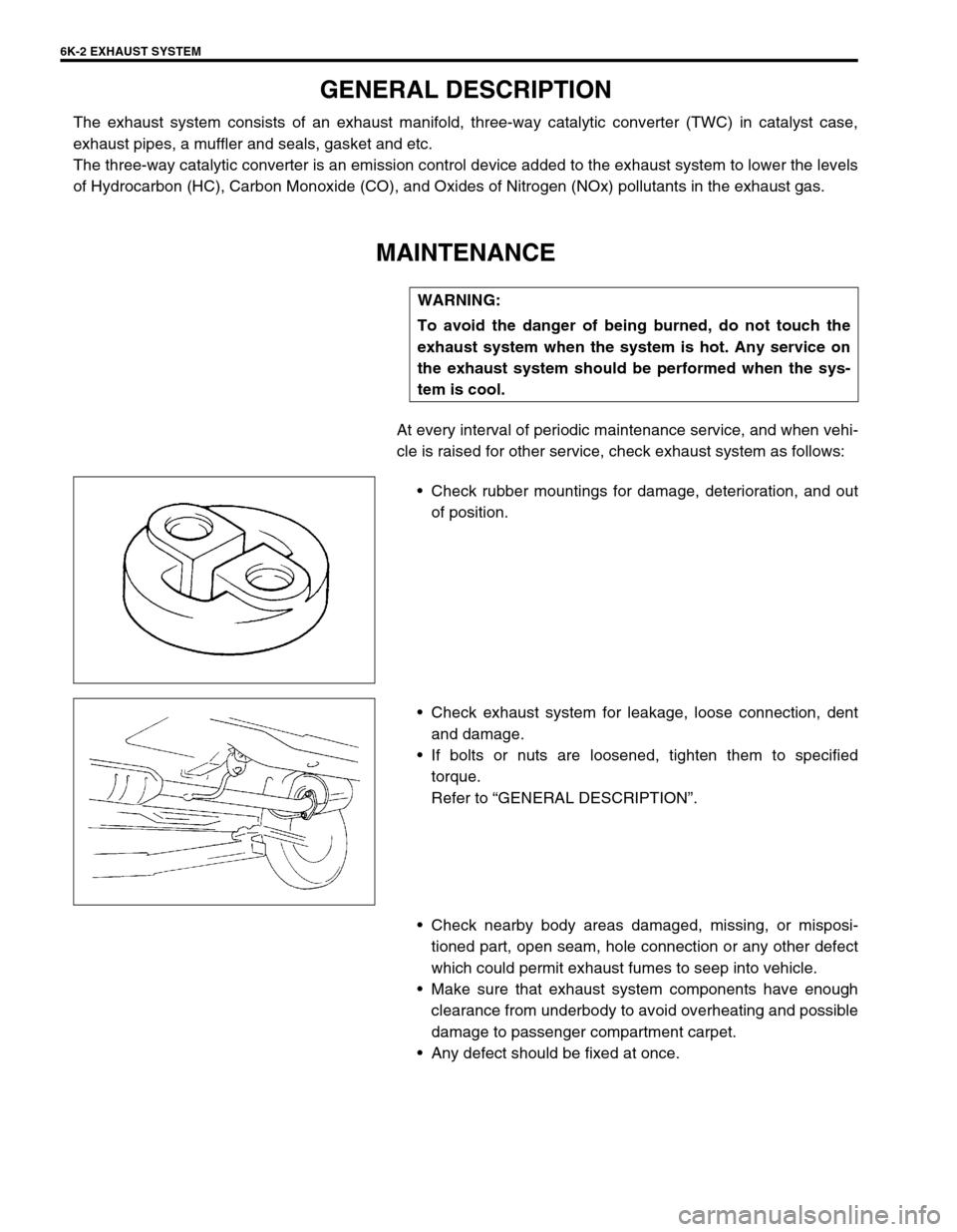
At every interval of periodic maintenance service, and when vehi-
cle is raised for other service, check exhaust system as follows:
Check rubber mountings for damage, deterioration, and out
of position.
Check exhaust system for leakage, loose connection, dent
and damage.
If bolts or nuts are loosened, tighten them to specified
torque.
Refer to “GENERAL DESCRIPTION”.
Check nearby body areas damaged, missing, or misposi-
tioned part, open seam, hole connection or any other defect
which could permit exhaust fumes to seep into vehicle.
Make sure that exhaust system components have enough
clearance from underbody to avoid overheating and possible
damage to passenger compartment carpet.
Any defect should be fixed at once. WARNING:
To avoid the danger of being burned, do not touch the
exhaust system when the system is hot. Any service on
the exhaust system should be performed when the sys-
tem is cool.
Page 697 of 698
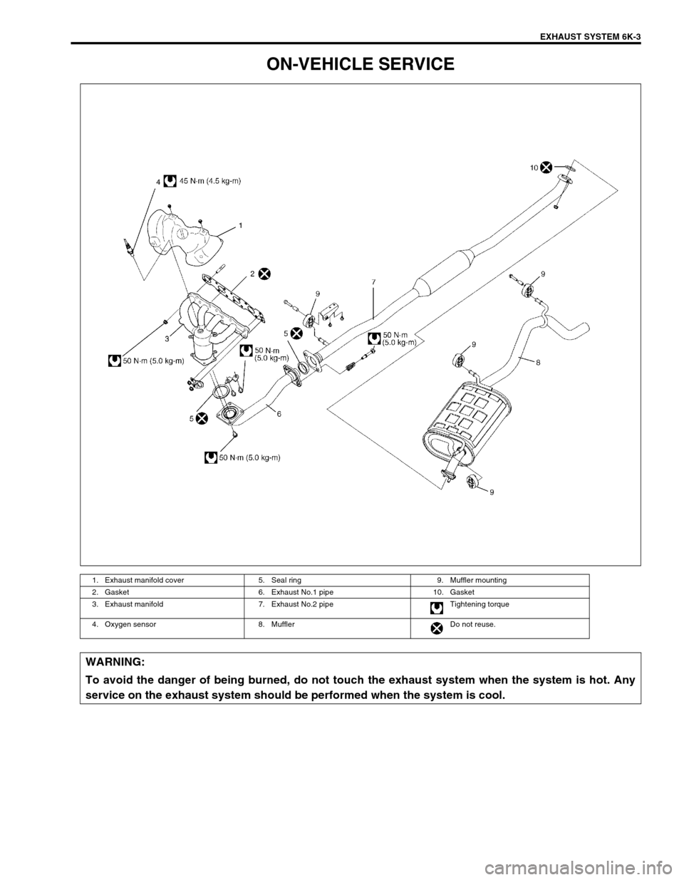
EXHAUST SYSTEM 6K-3
ON-VEHICLE SERVICE
1. Exhaust manifold cover 5. Seal ring 9. Muffler mounting
2. Gasket 6. Exhaust No.1 pipe 10. Gasket
3. Exhaust manifold 7. Exhaust No.2 pipe Tightening torque
4. Oxygen sensor 8. Muffler Do not reuse.
WARNING:
To avoid the danger of being burned, do not touch the exhaust system when the system is hot. Any
service on the exhaust system should be performed when the system is cool.