Torque SUZUKI SWIFT 2000 1.G RG413 Service Workshop Manual
[x] Cancel search | Manufacturer: SUZUKI, Model Year: 2000, Model line: SWIFT, Model: SUZUKI SWIFT 2000 1.GPages: 698, PDF Size: 16.01 MB
Page 538 of 698
ENGINE MECHANICAL (M13 ENGINE) 6A1-37
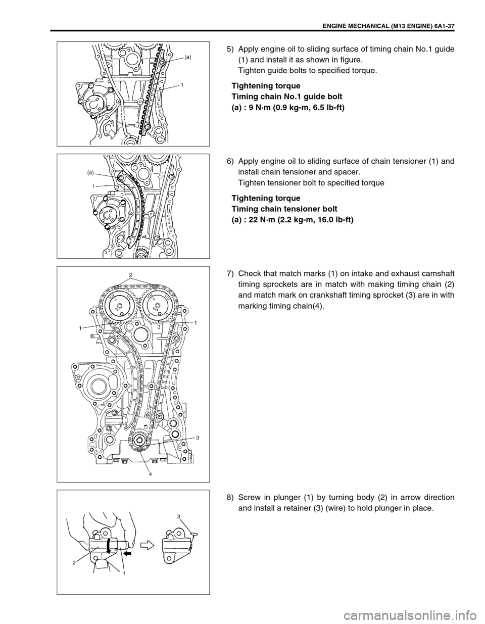
5) Apply engine oil to sliding surface of timing chain No.1 guide
(1) and install it as shown in figure.
Tighten guide bolts to specified torque.
Tightening torque
Timing chain No.1 guide bolt
(a) : 9 N·m (0.9 kg-m, 6.5 lb-ft)
6) Apply engine oil to sliding surface of chain tensioner (1) and
install chain tensioner and spacer.
Tighten tensioner bolt to specified torque
Tightening torque
Timing chain tensioner bolt
(a) : 22 N·m (2.2 kg-m, 16.0 lb-ft)
7) Check that match marks (1) on intake and exhaust camshaft
timing sprockets are in match with making timing chain (2)
and match mark on crankshaft timing sprocket (3) are in with
marking timing chain(4).
8) Screw in plunger (1) by turning body (2) in arrow direction
and install a retainer (3) (wire) to hold plunger in place.
Page 539 of 698
6A1-38 ENGINE MECHANICAL (M13 ENGINE)
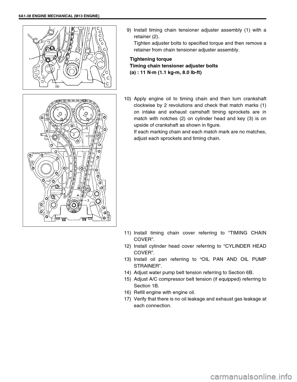
9) Install timing chain tensioner adjuster assembly (1) with a
retainer (2).
Tighten adjuster bolts to specified torque and then remove a
retainer from chain tensioner adjuster assembly.
Tightening torque
Timing chain tensioner adjuster bolts
(a) : 11 N·m (1.1 kg-m, 8.0 lb-ft)
10) Apply engine oil to timing chain and then turn crankshaft
clockwise by 2 revolutions and check that match marks (1)
on intake and exhaust camshaft timing sprockets are in
match with notches (2) on cylinder head and key (3) is on
upside of crankshaft as shown in figure.
If each marking chain and each match mark are no matches,
adjust each sprockets and timing chain.
11) Install timing chain cover referring to “TIMING CHAIN
COVER”.
12) Install cylinder head cover referring to “CYLINDER HEAD
COVER”.
13) Install oil pan referring to “OIL PAN AND OIL PUMP
STRAINER”.
14) Adjust water pump belt tension referring to Section 6B.
15) Adjust A/C compressor belt tension (if equipped) referring to
Section 1B.
16) Refill engine with engine oil.
17) Verify that there is no oil leakage and exhaust gas leakage at
each connection.
Page 540 of 698
ENGINE MECHANICAL (M13 ENGINE) 6A1-39
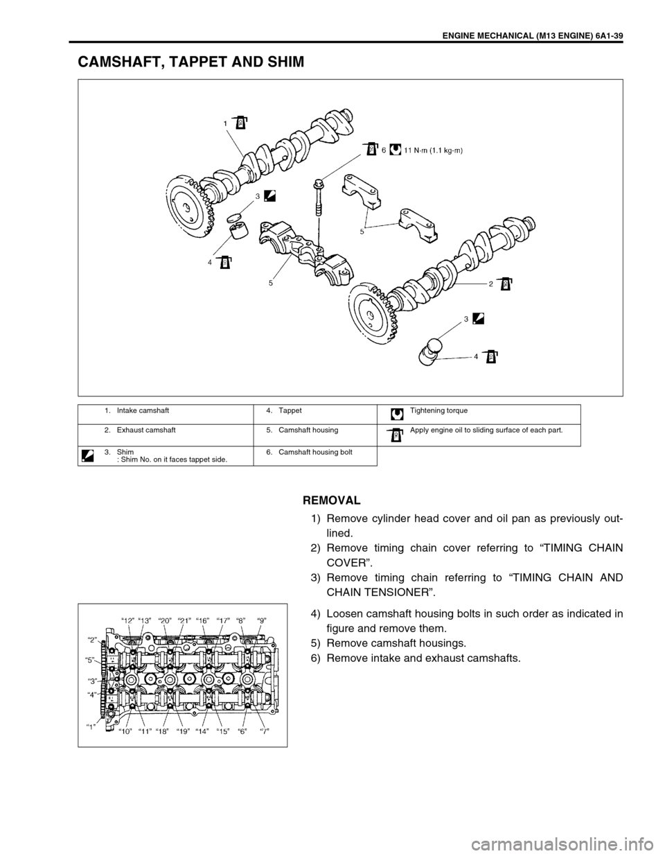
CAMSHAFT, TAPPET AND SHIM
REMOVAL
1) Remove cylinder head cover and oil pan as previously out-
lined.
2) Remove timing chain cover referring to “TIMING CHAIN
COVER”.
3) Remove timing chain referring to “TIMING CHAIN AND
CHAIN TENSIONER”.
4) Loosen camshaft housing bolts in such order as indicated in
figure and remove them.
5) Remove camshaft housings.
6) Remove intake and exhaust camshafts.
1. Intake camshaft 4. Tappet Tightening torque
2. Exhaust camshaft 5. Camshaft housing Apply engine oil to sliding surface of each part.
3. Shim
: Shim No. on it faces tappet side.6. Camshaft housing bolt
Page 542 of 698
ENGINE MECHANICAL (M13 ENGINE) 6A1-41
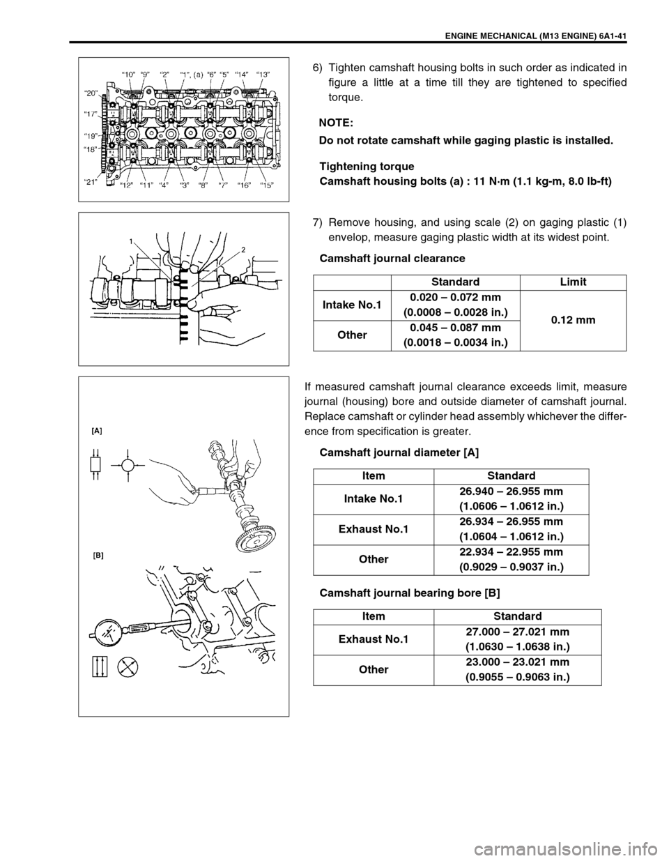
6) Tighten camshaft housing bolts in such order as indicated in
figure a little at a time till they are tightened to specified
torque.
Tightening torque
Camshaft housing bolts (a) : 11 N·m (1.1 kg-m, 8.0 lb-ft)
7) Remove housing, and using scale (2) on gaging plastic (1)
envelop, measure gaging plastic width at its widest point.
Camshaft journal clearance
If measured camshaft journal clearance exceeds limit, measure
journal (housing) bore and outside diameter of camshaft journal.
Replace camshaft or cylinder head assembly whichever the differ-
ence from specification is greater.
Camshaft journal diameter [A]
Camshaft journal bearing bore [B] NOTE:
Do not rotate camshaft while gaging plastic is installed.
Standard Limit
Intake No.10.020 – 0.072 mm
(0.0008 – 0.0028 in.)
0.12 mm
Other0.045 – 0.087 mm
(0.0018 – 0.0034 in.)
Item Standard
Intake No.126.940 – 26.955 mm
(1.0606 – 1.0612 in.)
Exhaust No.126.934 – 26.955 mm
(1.0604 – 1.0612 in.)
Other22.934 – 22.955 mm
(0.9029 – 0.9037 in.)
Item Standard
Exhaust No.127.000 – 27.021 mm
(1.0630 – 1.0638 in.)
Other23.000 – 23.021 mm
(0.9055 – 0.9063 in.)
Page 544 of 698
ENGINE MECHANICAL (M13 ENGINE) 6A1-43
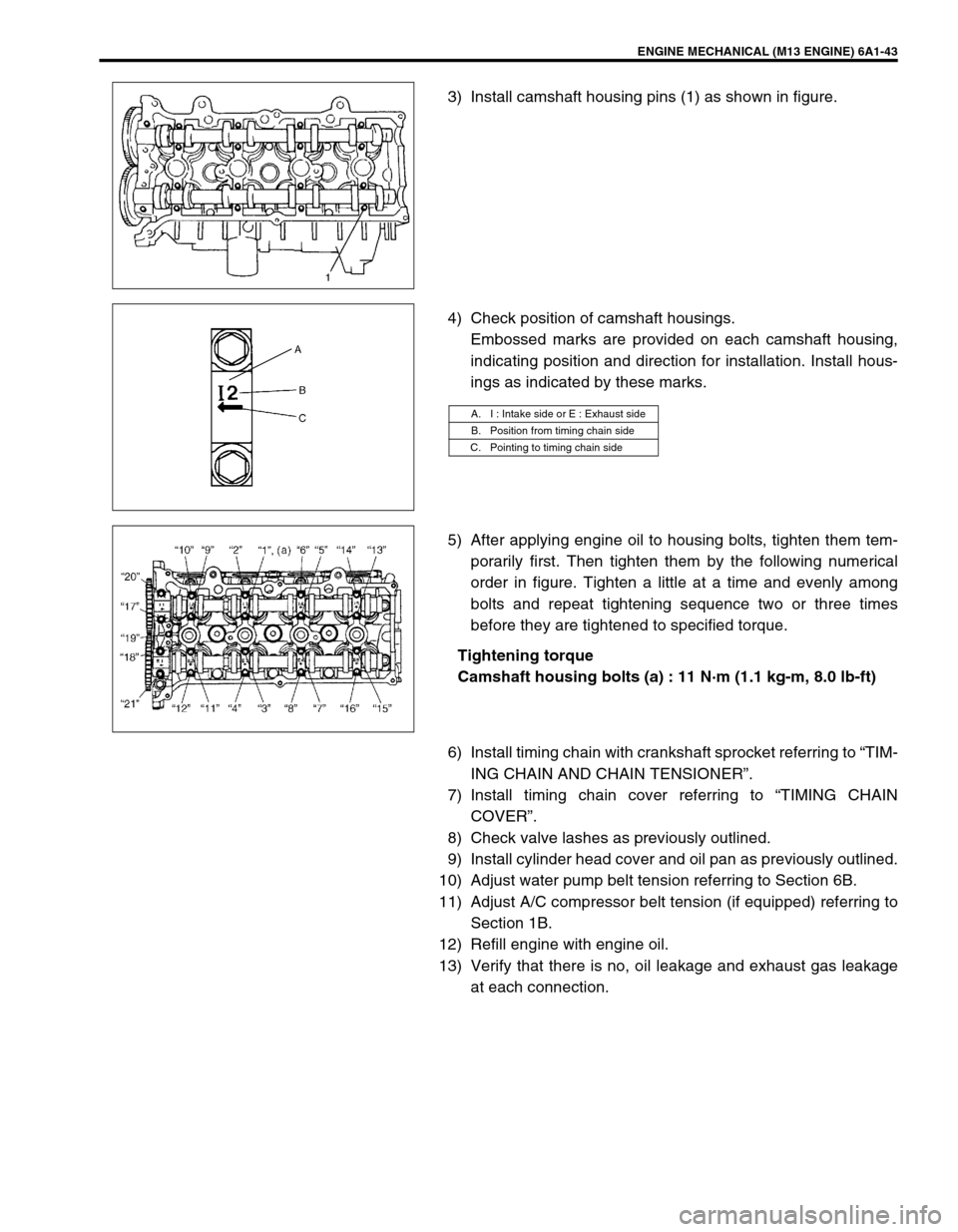
3) Install camshaft housing pins (1) as shown in figure.
4) Check position of camshaft housings.
Embossed marks are provided on each camshaft housing,
indicating position and direction for installation. Install hous-
ings as indicated by these marks.
5) After applying engine oil to housing bolts, tighten them tem-
porarily first. Then tighten them by the following numerical
order in figure. Tighten a little at a time and evenly among
bolts and repeat tightening sequence two or three times
before they are tightened to specified torque.
Tightening torque
Camshaft housing bolts (a) : 11 N·m (1.1 kg-m, 8.0 lb-ft)
6) Install timing chain with crankshaft sprocket referring to “TIM-
ING CHAIN AND CHAIN TENSIONER”.
7) Install timing chain cover referring to “TIMING CHAIN
COVER”.
8) Check valve lashes as previously outlined.
9) Install cylinder head cover and oil pan as previously outlined.
10) Adjust water pump belt tension referring to Section 6B.
11) Adjust A/C compressor belt tension (if equipped) referring to
Section 1B.
12) Refill engine with engine oil.
13) Verify that there is no, oil leakage and exhaust gas leakage
at each connection.
A. I : Intake side or E : Exhaust side
B. Position from timing chain side
C. Pointing to timing chain side
Page 545 of 698
6A1-44 ENGINE MECHANICAL (M13 ENGINE)
VALVES AND CYLINDER HEAD
REMOVAL
1) Relieve fuel pressure according to procedure described in
Section 6.
2) Disconnect negative cable at battery.
3) Drain engine oil.
[A]✱1) Tighten all bolts at 40 N·m (4.0 kg-m)
2) Turn all bolts at 60°
3) Then, Turn all bolt at 60° once again6. Intake valve 12. Knock pin
1. Valve cotters 7. Exhaust valve
Tightening torque
2. Valve spring retainer 8. Valve guide
Do not reuse.
3. Valve spring 9. Cylinder head bolt
: Never reuse it due to plastic deformation
tightening bolt.Apply engine oil to sliding surface of
each part.
4. Valve stem seal 10. Cylinder head
5. Valve spring seat 11. Cylinder head gasket
: “TOP” mark provided on gasket comes to
crankshaft pulley side, facing up.
Page 556 of 698
ENGINE MECHANICAL (M13 ENGINE) 6A1-55
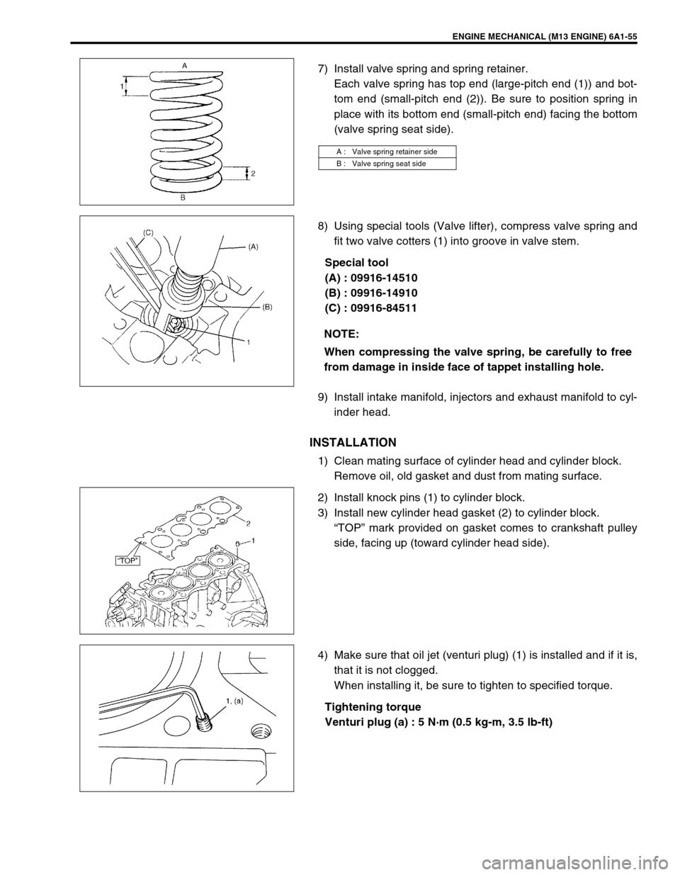
7) Install valve spring and spring retainer.
Each valve spring has top end (large-pitch end (1)) and bot-
tom end (small-pitch end (2)). Be sure to position spring in
place with its bottom end (small-pitch end) facing the bottom
(valve spring seat side).
8) Using special tools (Valve lifter), compress valve spring and
fit two valve cotters (1) into groove in valve stem.
Special tool
(A) : 09916-14510
(B) : 09916-14910
(C) : 09916-84511
9) Install intake manifold, injectors and exhaust manifold to cyl-
inder head.
INSTALLATION
1) Clean mating surface of cylinder head and cylinder block.
Remove oil, old gasket and dust from mating surface.
2) Install knock pins (1) to cylinder block.
3) Install new cylinder head gasket (2) to cylinder block.
“TOP” mark provided on gasket comes to crankshaft pulley
side, facing up (toward cylinder head side).
4) Make sure that oil jet (venturi plug) (1) is installed and if it is,
that it is not clogged.
When installing it, be sure to tighten to specified torque.
Tightening torque
Venturi plug (a) : 5 N·m (0.5 kg-m, 3.5 lb-ft)
A : Valve spring retainer side
B : Valve spring seat side
NOTE:
When compressing the valve spring, be carefully to free
from damage in inside face of tappet installing hole.
Page 557 of 698
6A1-56 ENGINE MECHANICAL (M13 ENGINE)
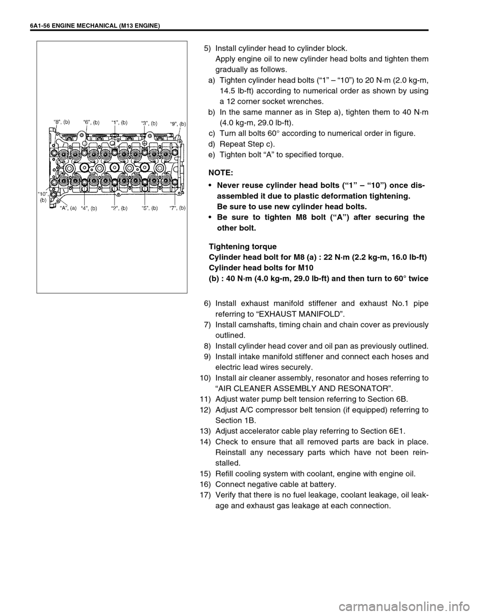
5) Install cylinder head to cylinder block.
Apply engine oil to new cylinder head bolts and tighten them
gradually as follows.
a) Tighten cylinder head bolts (“1” – “10”) to 20 N·m (2.0 kg-m,
14.5 lb-ft) according to numerical order as shown by using
a 12 corner socket wrenches.
b) In the same manner as in Step a), tighten them to 40 N·m
(4.0 kg-m, 29.0 lb-ft).
c) Turn all bolts 60° according to numerical order in figure.
d) Repeat Step c).
e) Tighten bolt “A” to specified torque.
Tightening torque
Cylinder head bolt for M8 (a) : 22 N·m (2.2 kg-m, 16.0 lb-ft)
Cylinder head bolts for M10
(b) : 40 N·m (4.0 kg-m, 29.0 lb-ft) and then turn to 60° twice
6) Install exhaust manifold stiffener and exhaust No.1 pipe
referring to “EXHAUST MANIFOLD”.
7) Install camshafts, timing chain and chain cover as previously
outlined.
8) Install cylinder head cover and oil pan as previously outlined.
9) Install intake manifold stiffener and connect each hoses and
electric lead wires securely.
10) Install air cleaner assembly, resonator and hoses referring to
“AIR CLEANER ASSEMBLY AND RESONATOR”.
11) Adjust water pump belt tension referring to Section 6B.
12) Adjust A/C compressor belt tension (if equipped) referring to
Section 1B.
13) Adjust accelerator cable play referring to Section 6E1.
14) Check to ensure that all removed parts are back in place.
Reinstall any necessary parts which have not been rein-
stalled.
15) Refill cooling system with coolant, engine with engine oil.
16) Connect negative cable at battery.
17) Verify that there is no fuel leakage, coolant leakage, oil leak-
age and exhaust gas leakage at each connection. NOTE:
Never reuse cylinder head bolts (“1” – “10”) once dis-
assembled it due to plastic deformation tightening.
Be sure to use new cylinder head bolts.
Be sure to tighten M8 bolt (“A”) after securing the
other bolt.
Page 558 of 698
ENGINE MECHANICAL (M13 ENGINE) 6A1-57
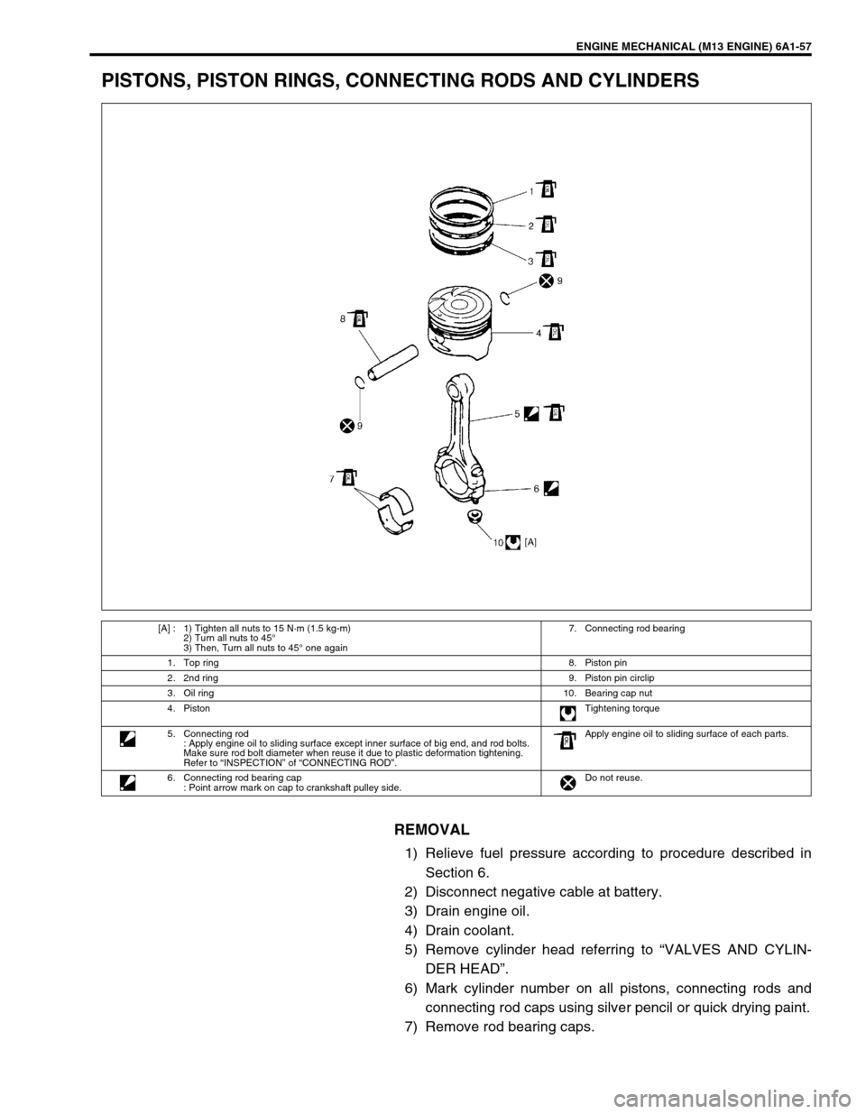
PISTONS, PISTON RINGS, CONNECTING RODS AND CYLINDERS
REMOVAL
1) Relieve fuel pressure according to procedure described in
Section 6.
2) Disconnect negative cable at battery.
3) Drain engine oil.
4) Drain coolant.
5) Remove cylinder head referring to “VALVES AND CYLIN-
DER HEAD”.
6) Mark cylinder number on all pistons, connecting rods and
connecting rod caps using silver pencil or quick drying paint.
7) Remove rod bearing caps.
[A] : 1) Tighten all nuts to 15 N·m (1.5 kg-m)
2) Turn all nuts to 45°
3) Then, Turn all nuts to 45° one again7. Connecting rod bearing
1. Top ring8. Piston pin
2. 2nd ring9. Piston pin circlip
3. Oil ring10. Bearing cap nut
4. PistonTightening torque
5. Connecting rod
: Apply engine oil to sliding surface except inner surface of big end, and rod bolts.
Make sure rod bolt diameter when reuse it due to plastic deformation tightening.
Refer to “INSPECTION” of “CONNECTING ROD”.Apply engine oil to sliding surface of each parts.
6. Connecting rod bearing cap
: Point arrow mark on cap to crankshaft pulley side.Do not reuse.
Page 564 of 698
ENGINE MECHANICAL (M13 ENGINE) 6A1-63
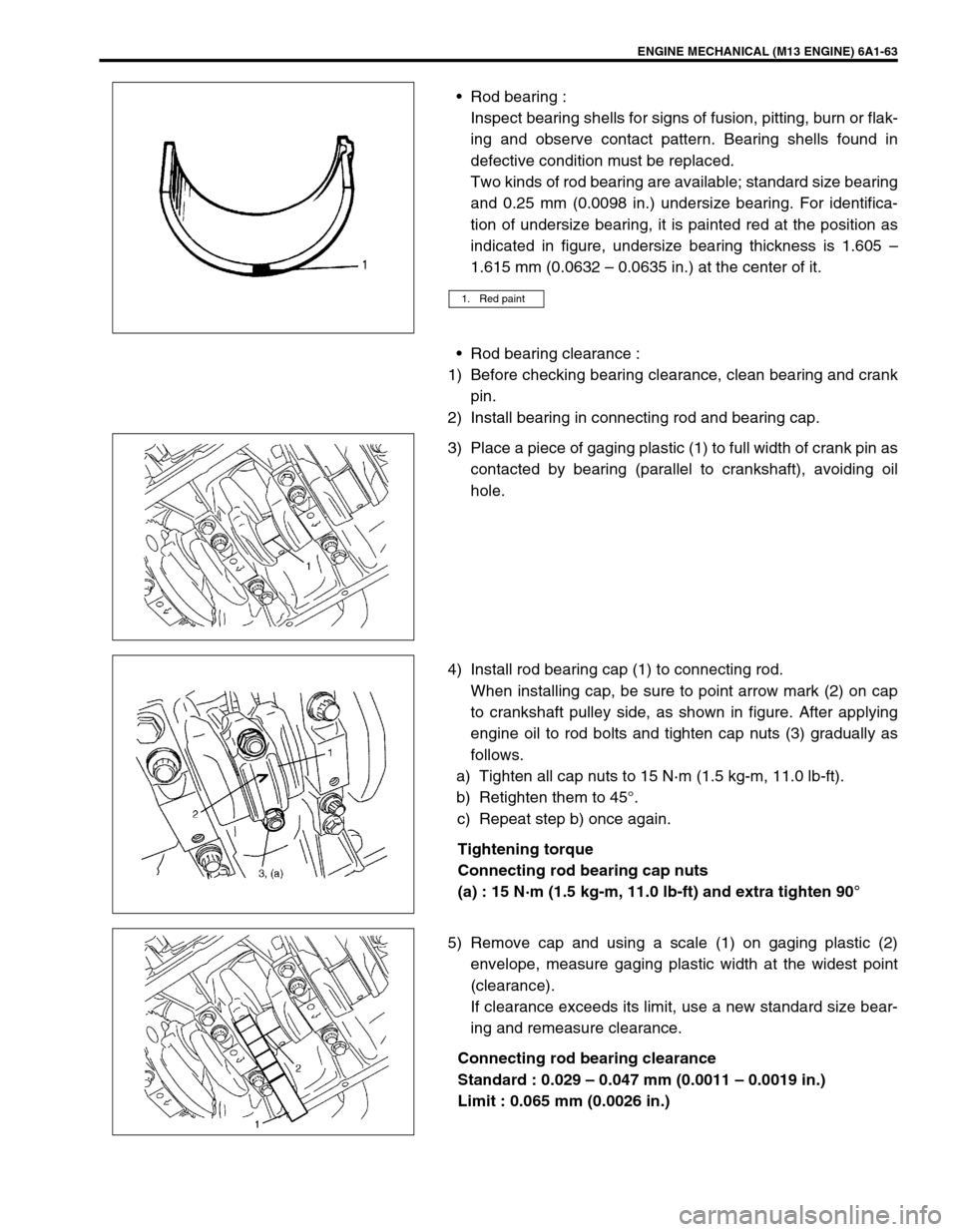
Rod bearing :
Inspect bearing shells for signs of fusion, pitting, burn or flak-
ing and observe contact pattern. Bearing shells found in
defective condition must be replaced.
Two kinds of rod bearing are available; standard size bearing
and 0.25 mm (0.0098 in.) undersize bearing. For identifica-
tion of undersize bearing, it is painted red at the position as
indicated in figure, undersize bearing thickness is 1.605 –
1.615 mm (0.0632 – 0.0635 in.) at the center of it.
Rod bearing clearance :
1) Before checking bearing clearance, clean bearing and crank
pin.
2) Install bearing in connecting rod and bearing cap.
3) Place a piece of gaging plastic (1) to full width of crank pin as
contacted by bearing (parallel to crankshaft), avoiding oil
hole.
4) Install rod bearing cap (1) to connecting rod.
When installing cap, be sure to point arrow mark (2) on cap
to crankshaft pulley side, as shown in figure. After applying
engine oil to rod bolts and tighten cap nuts (3) gradually as
follows.
a) Tighten all cap nuts to 15 N·m (1.5 kg-m, 11.0 lb-ft).
b) Retighten them to 45°.
c) Repeat step b) once again.
Tightening torque
Connecting rod bearing cap nuts
(a) : 15 N·m (1.5 kg-m, 11.0 lb-ft) and extra tighten 90°
5) Remove cap and using a scale (1) on gaging plastic (2)
envelope, measure gaging plastic width at the widest point
(clearance).
If clearance exceeds its limit, use a new standard size bear-
ing and remeasure clearance.
Connecting rod bearing clearance
Standard : 0.029 – 0.047 mm (0.0011 – 0.0019 in.)
Limit : 0.065 mm (0.0026 in.)
1. Red paint