Torque SUZUKI SWIFT 2000 1.G RG413 Service Workshop Manual
[x] Cancel search | Manufacturer: SUZUKI, Model Year: 2000, Model line: SWIFT, Model: SUZUKI SWIFT 2000 1.GPages: 698, PDF Size: 16.01 MB
Page 566 of 698
ENGINE MECHANICAL (M13 ENGINE) 6A1-65
INSTALLATION
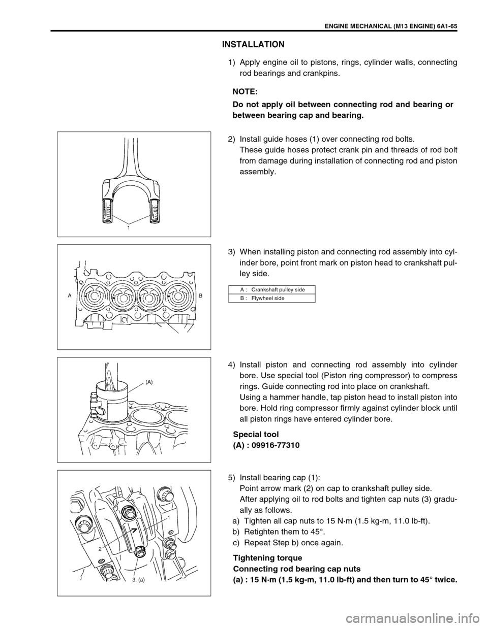
1) Apply engine oil to pistons, rings, cylinder walls, connecting
rod bearings and crankpins.
2) Install guide hoses (1) over connecting rod bolts.
These guide hoses protect crank pin and threads of rod bolt
from damage during installation of connecting rod and piston
assembly.
3) When installing piston and connecting rod assembly into cyl-
inder bore, point front mark on piston head to crankshaft pul-
ley side.
4) Install piston and connecting rod assembly into cylinder
bore. Use special tool (Piston ring compressor) to compress
rings. Guide connecting rod into place on crankshaft.
Using a hammer handle, tap piston head to install piston into
bore. Hold ring compressor firmly against cylinder block until
all piston rings have entered cylinder bore.
Special tool
(A) : 09916-77310
5) Install bearing cap (1):
Point arrow mark (2) on cap to crankshaft pulley side.
After applying oil to rod bolts and tighten cap nuts (3) gradu-
ally as follows.
a) Tighten all cap nuts to 15 N·m (1.5 kg-m, 11.0 lb-ft).
b) Retighten them to 45°.
c) Repeat Step b) once again.
Tightening torque
Connecting rod bearing cap nuts
(a) : 15 N·m (1.5 kg-m, 11.0 lb-ft) and then turn to 45° twice. NOTE:
Do not apply oil between connecting rod and bearing or
between bearing cap and bearing.
A : Crankshaft pulley side
B : Flywheel side
Page 568 of 698
![SUZUKI SWIFT 2000 1.G RG413 Service Workshop Manual ENGINE MECHANICAL (M13 ENGINE) 6A1-67
ENGINE MOUNTINGS
[A] : 4WD MODEL 3. Engine left mounting 6. Engine rear mounting No.1 bracket
1. Engine right mounting 4. Engine left mounting bracket 7. Engine r SUZUKI SWIFT 2000 1.G RG413 Service Workshop Manual ENGINE MECHANICAL (M13 ENGINE) 6A1-67
ENGINE MOUNTINGS
[A] : 4WD MODEL 3. Engine left mounting 6. Engine rear mounting No.1 bracket
1. Engine right mounting 4. Engine left mounting bracket 7. Engine r](/img/20/7606/w960_7606-567.png)
ENGINE MECHANICAL (M13 ENGINE) 6A1-67
ENGINE MOUNTINGS
[A] : 4WD MODEL 3. Engine left mounting 6. Engine rear mounting No.1 bracket
1. Engine right mounting 4. Engine left mounting bracket 7. Engine rear mounting No.2 bracket
2. Engine right body side bracket 5. Engine rear mounting Tightening torque
Page 572 of 698
ENGINE MECHANICAL (M13 ENGINE) 6A1-71
21) Before removing engine with transmission from body,
recheck to make sure all hoses, electric wires and cables are
disconnected from engine and transmission.
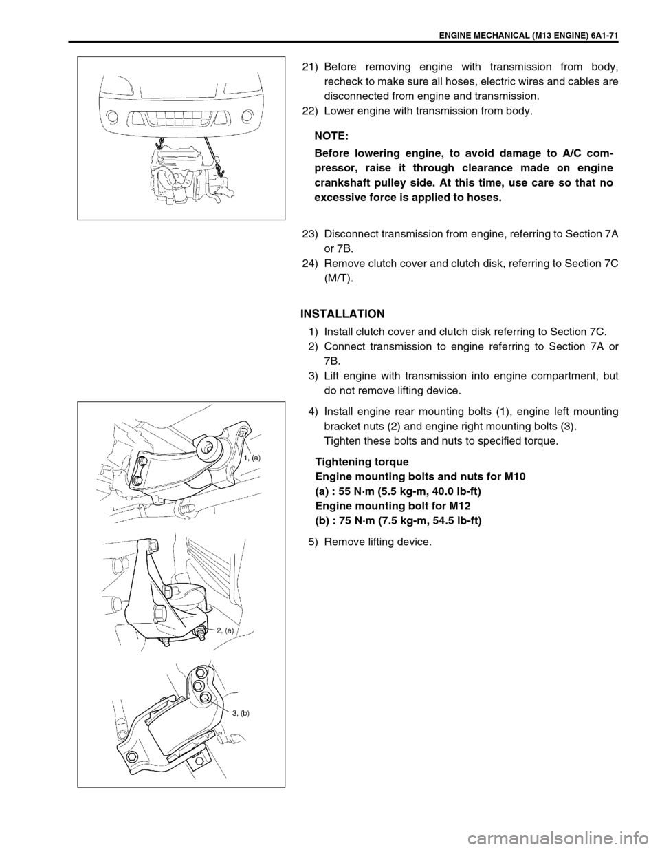
22) Lower engine with transmission from body.
23) Disconnect transmission from engine, referring to Section 7A
or 7B.
24) Remove clutch cover and clutch disk, referring to Section 7C
(M/T).
INSTALLATION
1) Install clutch cover and clutch disk referring to Section 7C.
2) Connect transmission to engine referring to Section 7A or
7B.
3) Lift engine with transmission into engine compartment, but
do not remove lifting device.
4) Install engine rear mounting bolts (1), engine left mounting
bracket nuts (2) and engine right mounting bolts (3).
Tighten these bolts and nuts to specified torque.
Tightening torque
Engine mounting bolts and nuts for M10
(a) : 55 N·m (5.5 kg-m, 40.0 lb-ft)
Engine mounting bolt for M12
(b) : 75 N·m (7.5 kg-m, 54.5 lb-ft)
5) Remove lifting device.NOTE:
Before lowering engine, to avoid damage to A/C com-
pressor, raise it through clearance made on engine
crankshaft pulley side. At this time, use care so that no
excessive force is applied to hoses.
Page 573 of 698
6A1-72 ENGINE MECHANICAL (M13 ENGINE)
6) Install generator referring to Section 6H.
7) For 4WD vehicle, install propeller shaft referring to Section
4B.
8) Connect drive shaft joints referring to Section 4.
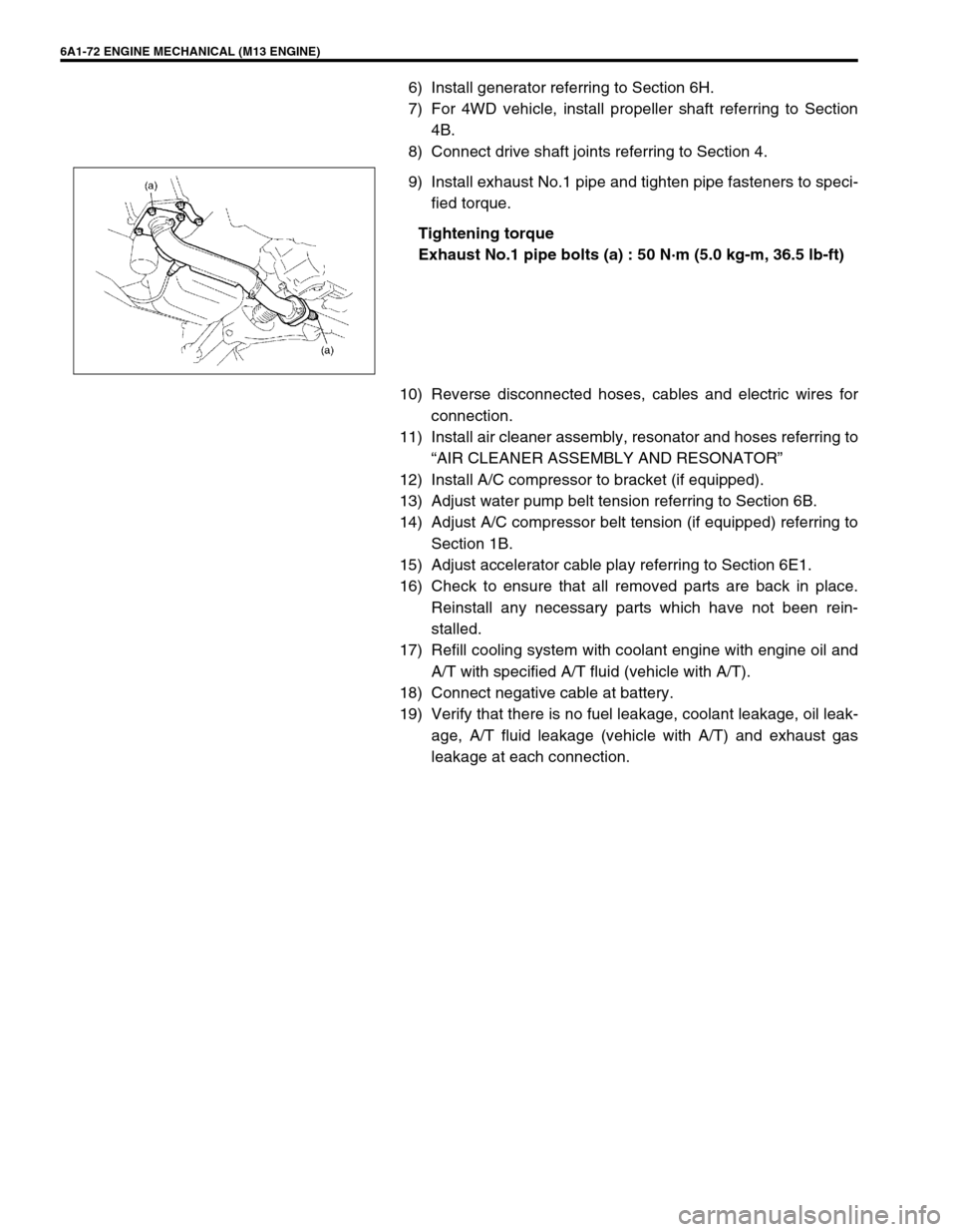
9) Install exhaust No.1 pipe and tighten pipe fasteners to speci-
fied torque.
Tightening torque
Exhaust No.1 pipe bolts (a) : 50 N·m (5.0 kg-m, 36.5 lb-ft)
10) Reverse disconnected hoses, cables and electric wires for
connection.
11) Install air cleaner assembly, resonator and hoses referring to
“AIR CLEANER ASSEMBLY AND RESONATOR”
12) Install A/C compressor to bracket (if equipped).
13) Adjust water pump belt tension referring to Section 6B.
14) Adjust A/C compressor belt tension (if equipped) referring to
Section 1B.
15) Adjust accelerator cable play referring to Section 6E1.
16) Check to ensure that all removed parts are back in place.
Reinstall any necessary parts which have not been rein-
stalled.
17) Refill cooling system with coolant engine with engine oil and
A/T with specified A/T fluid (vehicle with A/T).
18) Connect negative cable at battery.
19) Verify that there is no fuel leakage, coolant leakage, oil leak-
age, A/T fluid leakage (vehicle with A/T) and exhaust gas
leakage at each connection.
Page 575 of 698
6A1-74 ENGINE MECHANICAL (M13 ENGINE)
REMOVAL
1) Remove engine assembly from vehicle as previously out-
lined.
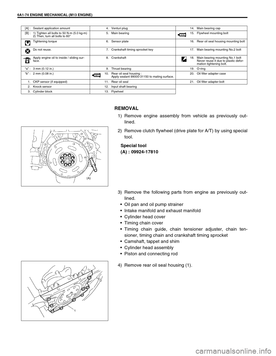
2) Remove clutch flywheel (drive plate for A/T) by using special
tool.
Special tool
(A) : 09924-17810
3) Remove the following parts from engine as previously out-
lined.
Oil pan and oil pump strainer
Intake manifold and exhaust manifold
Cylinder head cover
Timing chain cover
Timing chain guide, chain tensioner adjuster, chain ten-
sioner, timing chain and crankshaft timing sprocket
Camshaft, tappet and shim
Cylinder head assembly
Piston and connecting rod
4) Remove rear oil seal housing (1).
[A] : Sealant application amount 4. Venturi plug 14. Main bearing cap
[B] : 1) Tighten all bolts to 50 N·m (5.0 kg-m)
2) Then, turn all bolts to 60°5. Main bearing 15. Flywheel mounting bolt
Tightening torque 6. Sensor plate 16. Rear oil seal housing mounting bolt
Do not reuse. 7. Crankshaft timing sprocket key 17. Main bearing mounting No.2 bolt
Apply engine oil to inside / sliding sur-
face.8. Crankshaft
18. Main bearing mounting No.1 bolt
Never reuse it due to plastic defor-
mation tightening bolt.
“a” : 3 mm (0.12 in.) 9. Thrust bearing 19. O-ring
“b” : 2 mm (0.08 in.) 10. Rear oil seal housing :
Apply sealant 99000-31150 to mating surface.20. Oil filter adapter case
1. CKP sensor (if equipped) 11. Rear oil seal 21. Oil filter adapter bolt
2. Knock sensor 12. Input shaft bearing
3. Cylinder block 13. Flywheel
Page 576 of 698

ENGINE MECHANICAL (M13 ENGINE) 6A1-75
5) Loosen bearing cap No.1 and No.2 bolts in such order as
indicated in figure and remove them.
6) Remove crankshaft from cylinder block.
INSPECTION
Crankshaft
Crankshaft runout
Using a dial gauge, measure runout at center journal. Rotate
crankshaft slowly. If runout exceeds its limit, replace crankshaft.
Crankshaft runout
Limit : 0.04 mm (0.0016 in.)
Crankshaft thrust play
Measure this play with crankshaft set in cylinder block in the nor-
mal manner, that is with thrust bearing (1) and journal bearing
caps installed.
Thickness of crankshaft thrust bearing
Standard : 2.500 mm (0.0984 in.)
Oversize (0.125 mm (0.0049 in.)) : 2.563 mm (0.1009 in.)
Tighten bearing cap No.1 bolts (1) – (10) and No.2 bolts (11) –
(20) gradually as follows.
1) Tighten bolts (1) – (10) to 30 N·m (3.0 kg-m, 22.0 lb-ft)
according to numerical order in figure.
2) In the same manner as in Step 1), tighten them to 50 N·m
(5.0 kg-m, 36.5 lb-ft).
3) Tighten bolts (11) – (20) to 22 N·m (2.2 kg-m, 16.0 lb-ft)
according to numerical order in figure.
Tightening torque
Crank shaft bearing cap No.1 bolts (1) – (10)
: 50 N·m (5.0 kg-m, 36.5 lb-ft)
Crank shaft bearing cap No.2 bolts (11) – (20)
: 22 N·m (2.2 kg-m, 16.0 lb-ft)
Page 578 of 698
ENGINE MECHANICAL (M13 ENGINE) 6A1-77
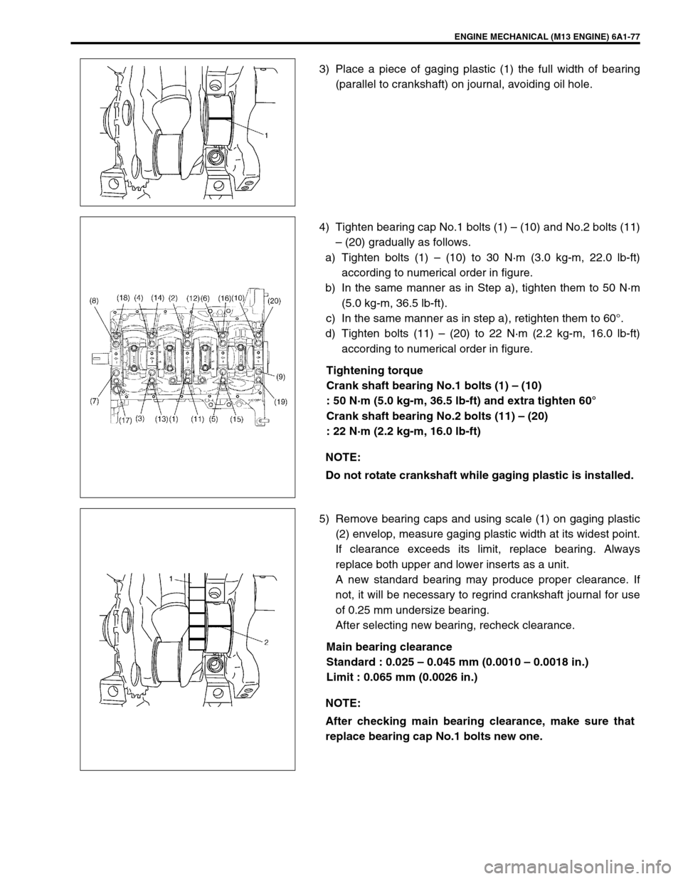
3) Place a piece of gaging plastic (1) the full width of bearing
(parallel to crankshaft) on journal, avoiding oil hole.
4) Tighten bearing cap No.1 bolts (1) – (10) and No.2 bolts (11)
– (20) gradually as follows.
a) Tighten bolts (1) – (10) to 30 N·m (3.0 kg-m, 22.0 lb-ft)
according to numerical order in figure.
b) In the same manner as in Step a), tighten them to 50 N·m
(5.0 kg-m, 36.5 lb-ft).
c) In the same manner as in step a), retighten them to 60°.
d) Tighten bolts (11) – (20) to 22 N·m (2.2 kg-m, 16.0 lb-ft)
according to numerical order in figure.
Tightening torque
Crank shaft bearing No.1 bolts (1) – (10)
: 50 N·m (5.0 kg-m, 36.5 lb-ft) and extra tighten 60°
Crank shaft bearing No.2 bolts (11) – (20)
: 22 N·m (2.2 kg-m, 16.0 lb-ft)
5) Remove bearing caps and using scale (1) on gaging plastic
(2) envelop, measure gaging plastic width at its widest point.
If clearance exceeds its limit, replace bearing. Always
replace both upper and lower inserts as a unit.
A new standard bearing may produce proper clearance. If
not, it will be necessary to regrind crankshaft journal for use
of 0.25 mm undersize bearing.
After selecting new bearing, recheck clearance.
Main bearing clearance
Standard : 0.025 – 0.045 mm (0.0010 – 0.0018 in.)
Limit : 0.065 mm (0.0026 in.)
NOTE:
Do not rotate crankshaft while gaging plastic is installed.
NOTE:
After checking main bearing clearance, make sure that
replace bearing cap No.1 bolts new one.
Page 584 of 698
ENGINE MECHANICAL (M13 ENGINE) 6A1-83
INSTALLATION
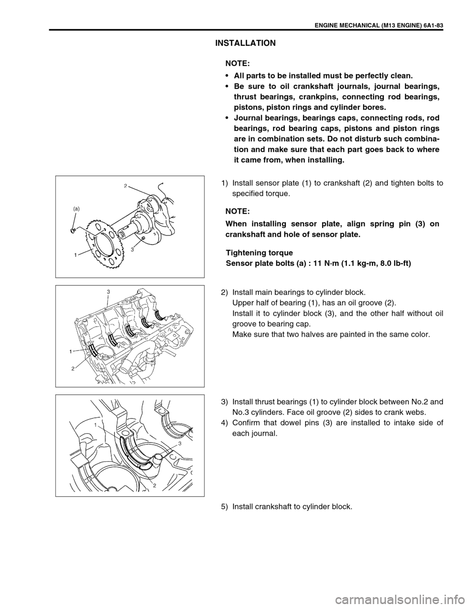
1) Install sensor plate (1) to crankshaft (2) and tighten bolts to
specified torque.
Tightening torque
Sensor plate bolts (a) : 11 N·m (1.1 kg-m, 8.0 lb-ft)
2) Install main bearings to cylinder block.
Upper half of bearing (1), has an oil groove (2).
Install it to cylinder block (3), and the other half without oil
groove to bearing cap.
Make sure that two halves are painted in the same color.
3) Install thrust bearings (1) to cylinder block between No.2 and
No.3 cylinders. Face oil groove (2) sides to crank webs.
4) Confirm that dowel pins (3) are installed to intake side of
each journal.
5) Install crankshaft to cylinder block.NOTE:
All parts to be installed must be perfectly clean.
Be sure to oil crankshaft journals, journal bearings,
thrust bearings, crankpins, connecting rod bearings,
pistons, piston rings and cylinder bores.
Journal bearings, bearings caps, connecting rods, rod
bearings, rod bearing caps, pistons and piston rings
are in combination sets. Do not disturb such combina-
tion and make sure that each part goes back to where
it came from, when installing.
NOTE:
When installing sensor plate, align spring pin (3) on
crankshaft and hole of sensor plate.
Page 585 of 698
6A1-84 ENGINE MECHANICAL (M13 ENGINE)
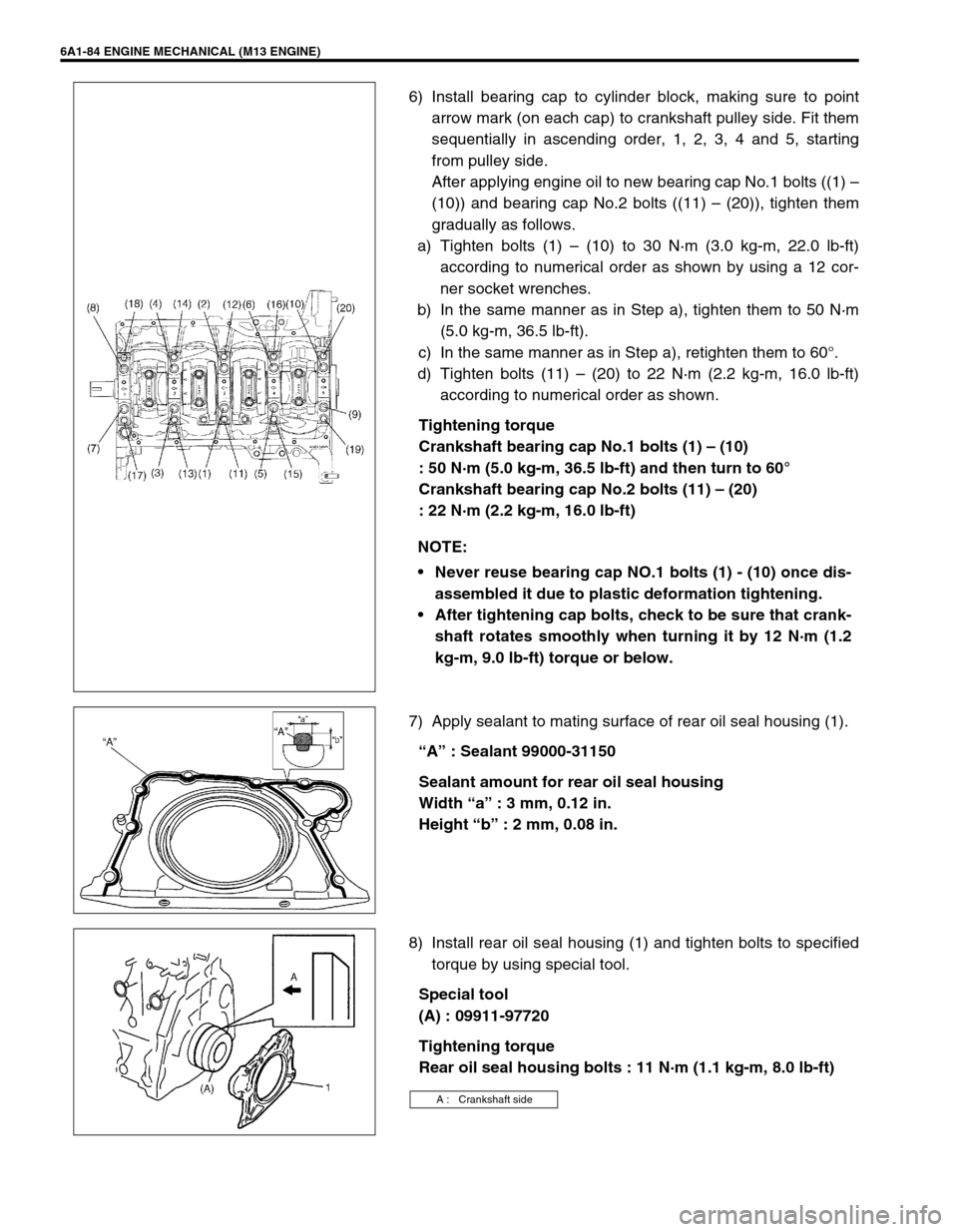
6) Install bearing cap to cylinder block, making sure to point
arrow mark (on each cap) to crankshaft pulley side. Fit them
sequentially in ascending order, 1, 2, 3, 4 and 5, starting
from pulley side.
After applying engine oil to new bearing cap No.1 bolts ((1) –
(10)) and bearing cap No.2 bolts ((11) – (20)), tighten them
gradually as follows.
a) Tighten bolts (1) – (10) to 30 N·m (3.0 kg-m, 22.0 lb-ft)
according to numerical order as shown by using a 12 cor-
ner socket wrenches.
b) In the same manner as in Step a), tighten them to 50 N·m
(5.0 kg-m, 36.5 lb-ft).
c) In the same manner as in Step a), retighten them to 60°.
d) Tighten bolts (11) – (20) to 22 N·m (2.2 kg-m, 16.0 lb-ft)
according to numerical order as shown.
Tightening torque
Crankshaft bearing cap No.1 bolts (1) – (10)
: 50 N·m (5.0 kg-m, 36.5 lb-ft) and then turn to 60°
Crankshaft bearing cap No.2 bolts (11) – (20)
: 22 N·m (2.2 kg-m, 16.0 lb-ft)
7) Apply sealant to mating surface of rear oil seal housing (1).
“A” : Sealant 99000-31150
Sealant amount for rear oil seal housing
Width “a” : 3 mm, 0.12 in.
Height “b” : 2 mm, 0.08 in.
8) Install rear oil seal housing (1) and tighten bolts to specified
torque by using special tool.
Special tool
(A) : 09911-97720
Tightening torque
Rear oil seal housing bolts : 11 N·m (1.1 kg-m, 8.0 lb-ft) NOTE:
Never reuse bearing cap NO.1 bolts (1) - (10) once dis-
assembled it due to plastic deformation tightening.
After tightening cap bolts, check to be sure that crank-
shaft rotates smoothly when turning it by 12 N·m (1.2
kg-m, 9.0 lb-ft) torque or below.
A : Crankshaft side
Page 586 of 698
ENGINE MECHANICAL (M13 ENGINE) 6A1-85
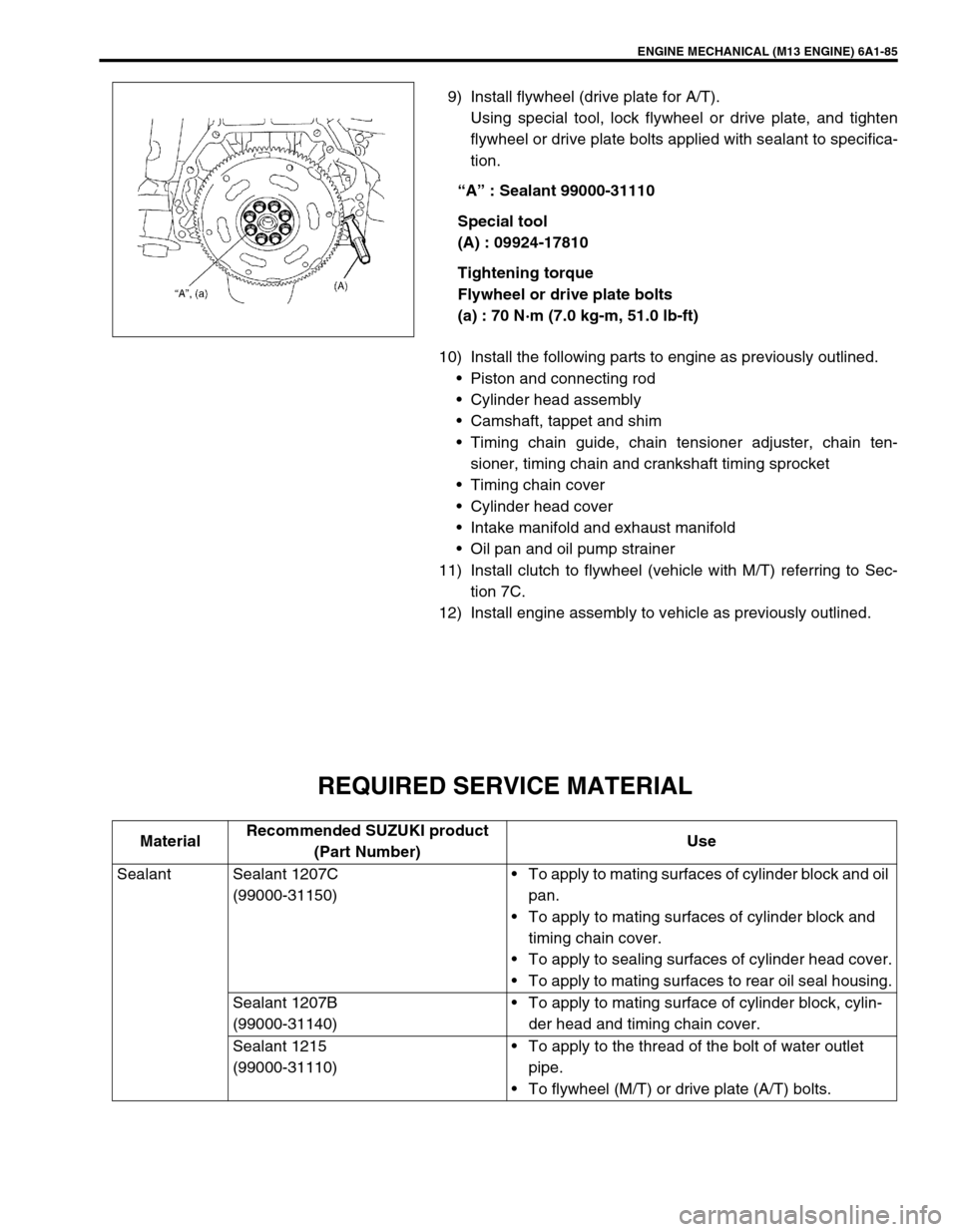
9) Install flywheel (drive plate for A/T).
Using special tool, lock flywheel or drive plate, and tighten
flywheel or drive plate bolts applied with sealant to specifica-
tion.
“A” : Sealant 99000-31110
Special tool
(A) : 09924-17810
Tightening torque
Flywheel or drive plate bolts
(a) : 70 N·m (7.0 kg-m, 51.0 lb-ft)
10) Install the following parts to engine as previously outlined.
Piston and connecting rod
Cylinder head assembly
Camshaft, tappet and shim
Timing chain guide, chain tensioner adjuster, chain ten-
sioner, timing chain and crankshaft timing sprocket
Timing chain cover
Cylinder head cover
Intake manifold and exhaust manifold
Oil pan and oil pump strainer
11) Install clutch to flywheel (vehicle with M/T) referring to Sec-
tion 7C.
12) Install engine assembly to vehicle as previously outlined.
REQUIRED SERVICE MATERIAL
MaterialRecommended SUZUKI product
(Part Number)Use
Sealant Sealant 1207C
(99000-31150)To apply to mating surfaces of cylinder block and oil
pan.
To apply to mating surfaces of cylinder block and
timing chain cover.
To apply to sealing surfaces of cylinder head cover.
To apply to mating surfaces to rear oil seal housing.
Sealant 1207B
(99000-31140)To apply to mating surface of cylinder block, cylin-
der head and timing chain cover.
Sealant 1215
(99000-31110)To apply to the thread of the bolt of water outlet
pipe.
To flywheel (M/T) or drive plate (A/T) bolts.