lock SUZUKI SWIFT 2000 1.G RG413 Service User Guide
[x] Cancel search | Manufacturer: SUZUKI, Model Year: 2000, Model line: SWIFT, Model: SUZUKI SWIFT 2000 1.GPages: 698, PDF Size: 16.01 MB
Page 28 of 698
GENERAL INFORMATION 0A-25
FASTENER INFORMATION
METRIC FASTENERS
Most of the fasteners used for this vehicle are metric. When replacing any fasteners, it is most important that
replacement fasteners be the correct diameter, thread pitch and strength.
FASTENER STRENGTH IDENTIFICATION
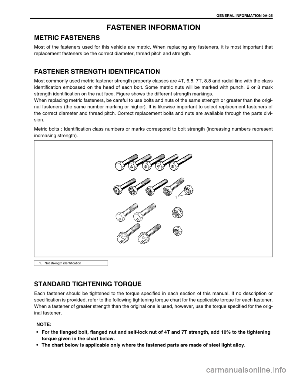
Most commonly used metric fastener strength property classes are 4T, 6.8, 7T, 8.8 and radial line with the class
identification embossed on the head of each bolt. Some metric nuts will be marked with punch, 6 or 8 mark
strength identification on the nut face. Figure shows the different strength markings.
When replacing metric fasteners, be careful to use bolts and nuts of the same strength or greater than the origi-
nal fasteners (the same number marking or higher). It is likewise important to select replacement fasteners of
the correct diameter and thread pitch. Correct replacement bolts and nuts are available through the parts divi-
sion.
Metric bolts : Identification class numbers or marks correspond to bolt strength (increasing numbers represent
increasing strength).
STANDARD TIGHTENING TORQUE
Each fastener should be tightened to the torque specified in each section of this manual. If no description or
specification is provided, refer to the following tightening torque chart for the applicable torque for each fastener.
When a fastener of greater strength than the original one is used, however, use the torque specified for the orig-
inal fastener.
1. Nut strength identification
NOTE:
For the flanged bolt, flanged nut and self-lock nut of 4T and 7T strength, add 10% to the tightening
torque given in the chart below.
The chart below is applicable only where the fastened parts are made of steel light alloy.
Page 29 of 698

0A-26 GENERAL INFORMATION
Tightening torque chart :
Thread Diameter (Nominal Diameter) (mm)
4 5 6 8 10 12 14 16 18
StrengthA equivalent of 4T strength
fastenerN·m 1.5 3.0 5.5 13 29 45 65 105 160
kg-m 0.15 0.30 0.55 1.3 2.9 4.5 6.5 10.5 16
lb-ft 1.0 2.5 4.0 9.5 21.0 32.5 47.0 76.0 116.0
A equivalent of 6.8 strength
fastener without flangeN·m 2.4 4.7 8.4 20 42 80 125 193 280
kg-m 0.24 0.47 0.84 2.0 4.2 8.0 12.5 19.3 28
lb-ft 2.0 3.5 6.0 14.5 30.5 58.0 90.5 139.5 202.5
A equivalent of 6.8 strength
fastener with flangeN·m 2.4 4.9 8.8 21 44 84 133 203 298
kg-m 0.24 0.49 0.88 2.1 4.4 8.4 13.3 20.3 29.8
lb-ft 2.0 3.5 6.5 15.5 32.0 61.0 96.5 147.0 215.5
A equivalent of 7T strength
fastenerN·m 2.3 4.5 10 23 50 85 135 210 240
kg-m 0.23 0.45 1.0 2.3 5.0 8.5 13.5 21 24
lb-ft 2.0 3.5 7.5 17.0 36.5 61.5 98.0 152.0 174.0
A equivalent of 8.8 strength
fastener without flangeN·m 3.1 6.3 11 27 56 105 168 258 373
kg-m 0.31 0.63 1.1 2.7 5.6 10.5 16.8 25.8 37.3
lb-ft 2.5 4.5 8.0 19.5 40.5 76.0 121.5 187.0 270.0
A equivalent of 8.8 strength
fastener with flangeN·m 3.2 6.5 12 29 59 113 175 270 395
kg-m 0.32 0.65 1.2 2.9 5.9 11.3 17.5 27 39.5
lb-ft 2.5 5.0 9.0 21.0 43.0 82.0 126.5 195.5 286.0
✱: Self-lock nut
Page 30 of 698
MAINTENANCE AND LUBRICATION 0B-1
0A 6F1
0B
0B
6G
1A 6H
1B 6K
37A
3A 7A1
3B1 7B1
3C1 7C1
3D 7D
3E 7E
3F 7F
4A2 8A
4B 8B
8C
58D
5A 8E
5B
5C 9
5E
5E1 10
10A
610B
6-1
6A1
6A2
6A4
6B
6C
6E1
6E2
SECTION 0B
MAINTENANCE AND LUBRICATION
CONTENTS
MAINTENANCE SCHEDULE .......................... 0B-2
MAINTENANCE SCHEDULE UNDER
NORMAL DRIVING CONDITIONS .............. 0B-2
MAINTENANCE RECOMMENDED UNDER
SEVERE DRIVING CONDITIONS ............... 0B-4
MAINTENANCE SERVICE .............................. 0B-5
ENGINE ....................................................... 0B-5
DRIVE BELT ............................................ 0B-5
VALVE LASH (CLEARANCE) .................. 0B-6
ENGINE OIL AND OIL FILTER ................ 0B-6
ENGINE COOLANT ................................. 0B-8
EXHAUST SYSTEM............................... 0B-10
IGNITION SYSTEM ................................... 0B-10
SPARK PLUGS ...................................... 0B-10
FUEL SYSTEM .......................................... 0B-10
AIR CLEANER FILTER .......................... 0B-10
FUEL LINES AND CONNECTIONS....... 0B-11
FUEL FILTER ......................................... 0B-11
FUEL TANK............................................ 0B-12
EMISSION CONTROL SYSTEM ............... 0B-12
PCV VALVE ........................................... 0B-12
FUEL EVAPORATIVE EMISSION
CONTROL SYSTEM .............................. 0B-12BRAKE ....................................................... 0B-12
BRAKE DISCS AND PADS (FRONT) .... 0B-12
BRAKE DRUMS AND SHOES
(REAR) ................................................... 0B-13
BRAKE HOSES AND PIPES ................. 0B-13
BRAKE FLUID........................................ 0B-13
BRAKE LEVER AND CABLE ................. 0B-13
CHASSIS AND BODY ............................... 0B-14
CLUTCH................................................. 0B-14
TIRES / WHEELS .................................. 0B-14
SUSPENSION SYSTEM ........................ 0B-15
STEERING SYSTEM ............................. 0B-15
DRIVE SHAFT (AXLE) BOOTS /
PROPELLER SHAFTS (4WD) ............... 0B-16
MANUAL TRANSMISSION OIL ............. 0B-17
AUTOMATIC TRANSMISSION FLUID .. 0B-17
TRANSFER OIL (4WD) AND REAR
DIFFERENTIAL OIL (4WD) ................... 0B-18
ALL LATCHES, HINGES AND
LOCKS ................................................... 0B-19
FINAL INSPECTION ..................................... 0B-19
RECOMMENDED FLUIDS AND
LUBRICANTS................................................ 0B-21
WARNING:
For vehicles equipped with Supplemental Restraint (Air Bag) System:
Service on and around the air bag system components or wiring must be performed only by an
authorized SUZUKI dealer. Refer to “Air Bag System Components and Wiring Location View” under
“General Description” in air bag system section in order to confirm whether you are performing ser-
vice on or near the air bag system components or wiring. Please observe all WARNINGS and “Ser-
vice Precautions” under “On-Vehicle Service” in air bag system section before performing service
on or around the air bag system components or wiring. Failure to follow WARNINGS could result in
unintentional activation of the system or could render the system inoperative. Either of these two
conditions may result in severe injury.
Technical service work must be started at least 90 seconds after the ignition switch is turned to the
“LOCK” position and the negative cable is disconnected from the battery. Otherwise, the system
may be activated by reserve energy in the Sensing and Diagnostic Module (SDM).
Page 32 of 698
MAINTENANCE AND LUBRICATION 0B-3
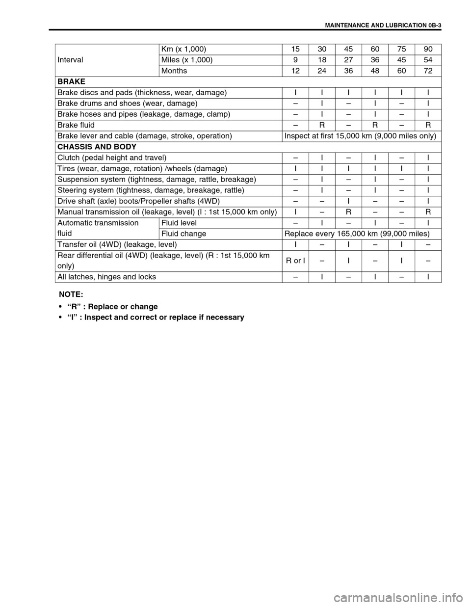
IntervalKm (x 1,000) 153045607590
Miles (x 1,000) 9 18 27 36 45 54
Months 12 24 36 48 60 72
BRAKE
Brake discs and pads (thickness, wear, damage) I I I I I I
Brake drums and shoes (wear, damage)–I–I–I
Brake hoses and pipes (leakage, damage, clamp)–I–I–I
Brake fluid–R–R–R
Brake lever and cable (damage, stroke, operation) Inspect at first 15,000 km (9,000 miles only)
CHASSIS AND BODY
Clutch (pedal height and travel)–I–I–I
Tires (wear, damage, rotation) /wheels (damage) I I I I I I
Suspension system (tightness, damage, rattle, breakage)–I–I–I
Steering system (tightness, damage, breakage, rattle)–I–I–I
Drive shaft (axle) boots/Propeller shafts (4WD)––I––I
Manual transmission oil (leakage, level) (I : 1st 15,000 km only) I–R––R
Automatic transmission
fluidFluid level–I–I–I
Fluid change Replace every 165,000 km (99,000 miles)
Transfer oil (4WD) (leakage, level) I–I–I–
Rear differential oil (4WD) (leakage, level) (R : 1st 15,000 km
only)R or I–I–I–
All latches, hinges and locks–I–I–I
NOTE:
“R” : Replace or change
“I” : Inspect and correct or replace if necessary
Page 48 of 698
MAINTENANCE AND LUBRICATION 0B-19
ALL LATCHES, HINGES AND LOCKS
INSPECTION
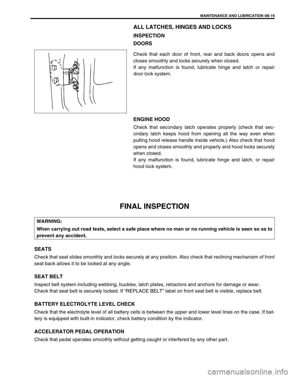
DOORS
Check that each door of front, rear and back doors opens and
closes smoothly and locks securely when closed.
If any malfunction is found, lubricate hinge and latch or repair
door lock system.
ENGINE HOOD
Check that secondary latch operates properly (check that sec-
ondary latch keeps hood from opening all the way even when
pulling hood release handle inside vehicle.) Also check that hood
opens and closes smoothly and properly and hood locks securely
when closed.
If any malfunction is found, lubricate hinge and latch, or repair
hood lock system.
FINAL INSPECTION
SEATS
Check that seat slides smoothly and locks securely at any position. Also check that reclining mechanism of front
seat back allows it to be locked at any angle.
SEAT BELT
Inspect belt system including webbing, buckles, latch plates, retractors and anchors for damage or wear.
Check that seat belt is securely locked. If “REPLACE BELT” label on front seat belt is visible, replace belt.
BATTERY ELECTROLYTE LEVEL CHECK
Check that the electrolyte level of all battery cells is between the upper and lower level lines on the case. If bat-
tery is equipped with built-in indicator, check battery condition by the indicator.
ACCELERATOR PEDAL OPERATION
Check that pedal operates smoothly without getting caught or interfered by any other part.
WARNING:
When carrying out road tests, select a safe place where no man or no running vehicle is seen so as to
prevent any accident.
Page 50 of 698
MAINTENANCE AND LUBRICATION 0B-21
STEERING
Check to ensure that steering wheel is free from instability, or abnormally heavy feeling.
Check that the vehicle does not wander or pull to one side.
ENGINE
Check that engine responds readily at all speeds.
Check that engine is free from abnormal noise and abnormal vibration.
BODY, WHEELS AND POWER TRANSMITTING SYSTEM
Check that body, wheels and power transmitting system are free from abnormal noise and abnormal vibration or
any other abnormal condition.
METERS AND GAUGE
Check that speedometer, odometer, fuel meter, temperature gauge, etc. are operating accurately.
LIGHTS
Check that all lights operate properly.
WINDSHIELD DEFROSTER
Periodically check that air comes out from defroster outlet when operating heater or air conditioning.
Set mode control lever to defroster position and fan switch lever to “HI” position for this check.
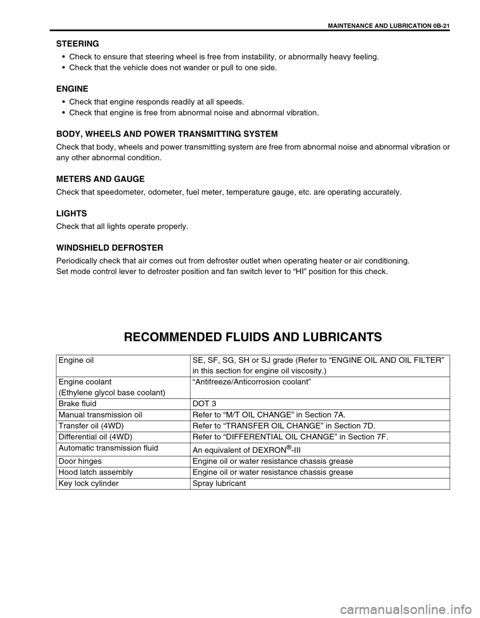
RECOMMENDED FLUIDS AND LUBRICANTS
Engine oil SE, SF, SG, SH or SJ grade (Refer to “ENGINE OIL AND OIL FILTER”
in this section for engine oil viscosity.)
Engine coolant
(Ethylene glycol base coolant)“Antifreeze/Anticorrosion coolant”
Brake fluid DOT 3
Manual transmission oil Refer to “M/T OIL CHANGE” in Section 7A.
Transfer oil (4WD) Refer to “TRANSFER OIL CHANGE” in Section 7D.
Differential oil (4WD) Refer to “DIFFERENTIAL OIL CHANGE” in Section 7F.
Automatic transmission fluid
An equivalent of DEXRON
®-III
Door hinges Engine oil or water resistance chassis grease
Hood latch assembly Engine oil or water resistance chassis grease
Key lock cylinder Spray lubricant
Page 52 of 698
HEATER AND VENTILATION 1A-1
6F1
6F2
6G
1A
6K
7A
7A1
7B1
7C1
7D
7E
7F
8A
8B
8C
8D
8E
9
10
10A
10B
SECTION 1A
HEATER AND VENTILATION
CONTENTS
GENERAL DESCRIPTION .............................. 1A-2
DIAGNOSIS ..................................................... 1A-3
DIAGNOSIS TABLE ..................................... 1A-3
WIRING CIRCUIT ........................................ 1A-4
ON-VEHICLE SERVICE .................................. 1A-5
HEATER UNIT ............................................. 1A-5BLOWER FAN MOTOR ............................... 1A-7
BLOWER FAN MOTOR RESISTOR ........... 1A-8
HEATER CONTROL ASSEMBLY ............... 1A-9
AIR INLET BOX ......................................... 1A-12
VENTILATION LOUVER............................ 1A-13
REQUIRED SERVICE MATERIALS ............. 1A-14
WARNING:
For vehicles equipped with Supplement Restraint (Air Bag) System
Service on and around the air bag system components or wiring must be performed only by an
authorized SUZUKI dealer. Refer to “Air Bag System Components and Wiring Location View” under
“General Description” in Section 10B in order to confirm whether you are performing service on or
near the air bag system components or wiring. Please observe all WARNINGS and “Service Precau-
tions” under “On-Vehicle Service” in Section 10B before performing service on or around the air
bag system components or wiring. Failure to follow WARNINGS could result in unintentional activa-
tion of the system or could render the system inoperative. Either or these two conditions may result
in severe injury.
Technical service work must be started at least 90 seconds after the ignition switch is turned to the
“LOCK” position and the negative cable is disconnected from the battery. Otherwise, the system
may be activated by reserve energy in the Sensing and Diagnostic Module (SDM).
NOTE:
The link mechanism of the heater varies depending on the specifications.
Page 59 of 698
1A-8 HEATER AND VENTILATION
BLOWER FAN MOTOR RESISTOR
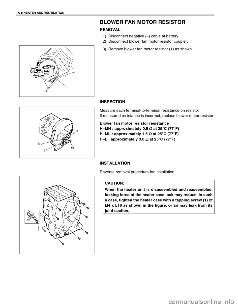
REMOVAL
1) Disconnect negative (–) cable at battery.
2) Disconnect blower fan motor resistor coupler.
3) Remove blower fan motor resistor (1) as shown.
INSPECTION
Measure each terminal-to-terminal resistance on resistor
If measured resistance is incorrect, replace blower motor resistor.
Blower fan motor resistor resistance
H–MH : approximately 0.5
Ω
ΩΩ Ω at 25°C (77°F)
H–ML : approximately 1.5
Ω
ΩΩ Ω at 25°C (77°F)
H–L : approximately 3.0
Ω
ΩΩ Ω at 25°C (77°F)
INSTALLATION
Reverse removal procedure for installation.
CAUTION:
When the heater unit is disassembled and reassembled,
locking force of the heater case lock may reduce. In such
a case, tighten the heater case with a tapping screw (1) of
M4 x L16 as shown in the figure, or air may leak from its
joint section.
1
Page 60 of 698
HEATER AND VENTILATION 1A-9
HEATER CONTROL ASSEMBLY
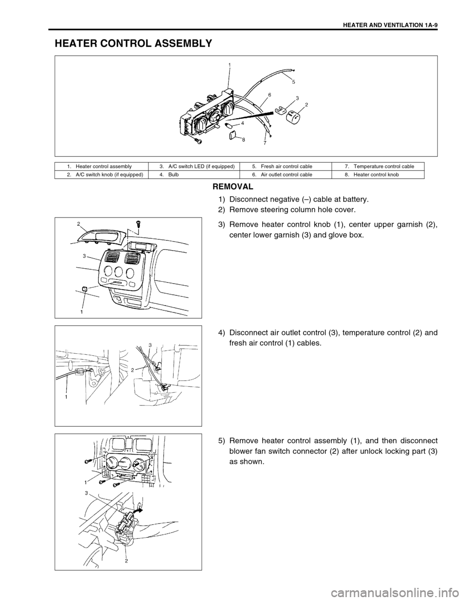
REMOVAL
1) Disconnect negative (–) cable at battery.
2) Remove steering column hole cover.
3) Remove heater control knob (1), center upper garnish (2),
center lower garnish (3) and glove box.
4) Disconnect air outlet control (3), temperature control (2) and
fresh air control (1) cables.
5) Remove heater control assembly (1), and then disconnect
blower fan switch connector (2) after unlock locking part (3)
as shown.
1. Heater control assembly 3. A/C switch LED (if equipped) 5. Fresh air control cable 7. Temperature control cable
2. A/C switch knob (if equipped) 4. Bulb 6. Air outlet control cable 8. Heater control knob
Page 66 of 698
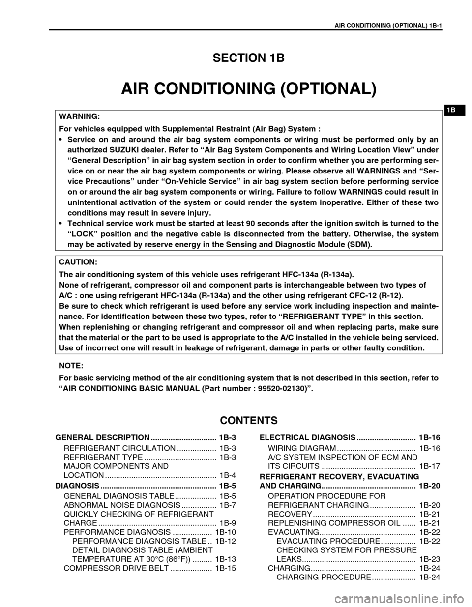
AIR CONDITIONING (OPTIONAL) 1B-1
6F1
6F2
6G
1B
7A
7A1
7B1
7C1
7D
7E
7F
8A
8B
8C
8D
8E
9
10
10A
10B
SECTION 1B
AIR CONDITIONING (OPTIONAL)
CONTENTS
GENERAL DESCRIPTION .............................. 1B-3
REFRIGERANT CIRCULATION .................. 1B-3
REFRIGERANT TYPE ................................. 1B-3
MAJOR COMPONENTS AND
LOCATION ................................................... 1B-4
DIAGNOSIS ..................................................... 1B-5
GENERAL DIAGNOSIS TABLE ................... 1B-5
ABNORMAL NOISE DIAGNOSIS ................ 1B-7
QUICKLY CHECKING OF REFRIGERANT
CHARGE ...................................................... 1B-9
PERFORMANCE DIAGNOSIS .................. 1B-10
PERFORMANCE DIAGNOSIS TABLE .. 1B-12
DETAIL DIAGNOSIS TABLE (AMBIENT
TEMPERATURE AT 30°C (86°F)) ......... 1B-13
COMPRESSOR DRIVE BELT ................... 1B-15ELECTRICAL DIAGNOSIS ........................... 1B-16
WIRING DIAGRAM .................................... 1B-16
A/C SYSTEM INSPECTION OF ECM AND
ITS CIRCUITS ........................................... 1B-17
REFRIGERANT RECOVERY, EVACUATING
AND CHARGING........................................... 1B-20
OPERATION PROCEDURE FOR
REFRIGERANT CHARGING ..................... 1B-20
RECOVERY ............................................... 1B-21
REPLENISHING COMPRESSOR OIL ...... 1B-21
EVACUATING............................................ 1B-22
EVACUATING PROCEDURE ................ 1B-22
CHECKING SYSTEM FOR PRESSURE
LEAKS.................................................... 1B-23
CHARGING................................................ 1B-24
CHARGING PROCEDURE .................... 1B-24 WARNING:
For vehicles equipped with Supplemental Restraint (Air Bag) System :
Service on and around the air bag system components or wiring must be performed only by an
authorized SUZUKI dealer. Refer to “Air Bag System Components and Wiring Location View” under
“General Description” in air bag system section in order to confirm whether you are performing ser-
vice on or near the air bag system components or wiring. Please observe all WARNINGS and “Ser-
vice Precautions” under “On-Vehicle Service” in air bag system section before performing service
on or around the air bag system components or wiring. Failure to follow WARNINGS could result in
unintentional activation of the system or could render the system inoperative. Either of these two
conditions may result in severe injury.
Technical service work must be started at least 90 seconds after the ignition switch is turned to the
“LOCK” position and the negative cable is disconnected from the battery. Otherwise, the system
may be activated by reserve energy in the Sensing and Diagnostic Module (SDM).
CAUTION:
The air conditioning system of this vehicle uses refrigerant HFC-134a (R-134a).
None of refrigerant, compressor oil and component parts is interchangeable between two types of
A/C : one using refrigerant HFC-134a (R-134a) and the other using refrigerant CFC-12 (R-12).
Be sure to check which refrigerant is used before any service work including inspection and mainte-
nance. For identification between these two types, refer to “REFRIGERANT TYPE” in this section.
When replenishing or changing refrigerant and compressor oil and when replacing parts, make sure
that the material or the part to be used is appropriate to the A/C installed in the vehicle being serviced.
Use of incorrect one will result in leakage of refrigerant, damage in parts or other faulty condition.
NOTE:
For basic servicing method of the air conditioning system that is not described in this section, refer to
“AIR CONDITIONING BASIC MANUAL (Part number : 99520-02130)”.