SUZUKI SWIFT 2000 1.G RG413 Service Workshop Manual
[x] Cancel search | Manufacturer: SUZUKI, Model Year: 2000, Model line: SWIFT, Model: SUZUKI SWIFT 2000 1.GPages: 698, PDF Size: 16.01 MB
Page 551 of 698
6A1-50 ENGINE MECHANICAL (M13 ENGINE)
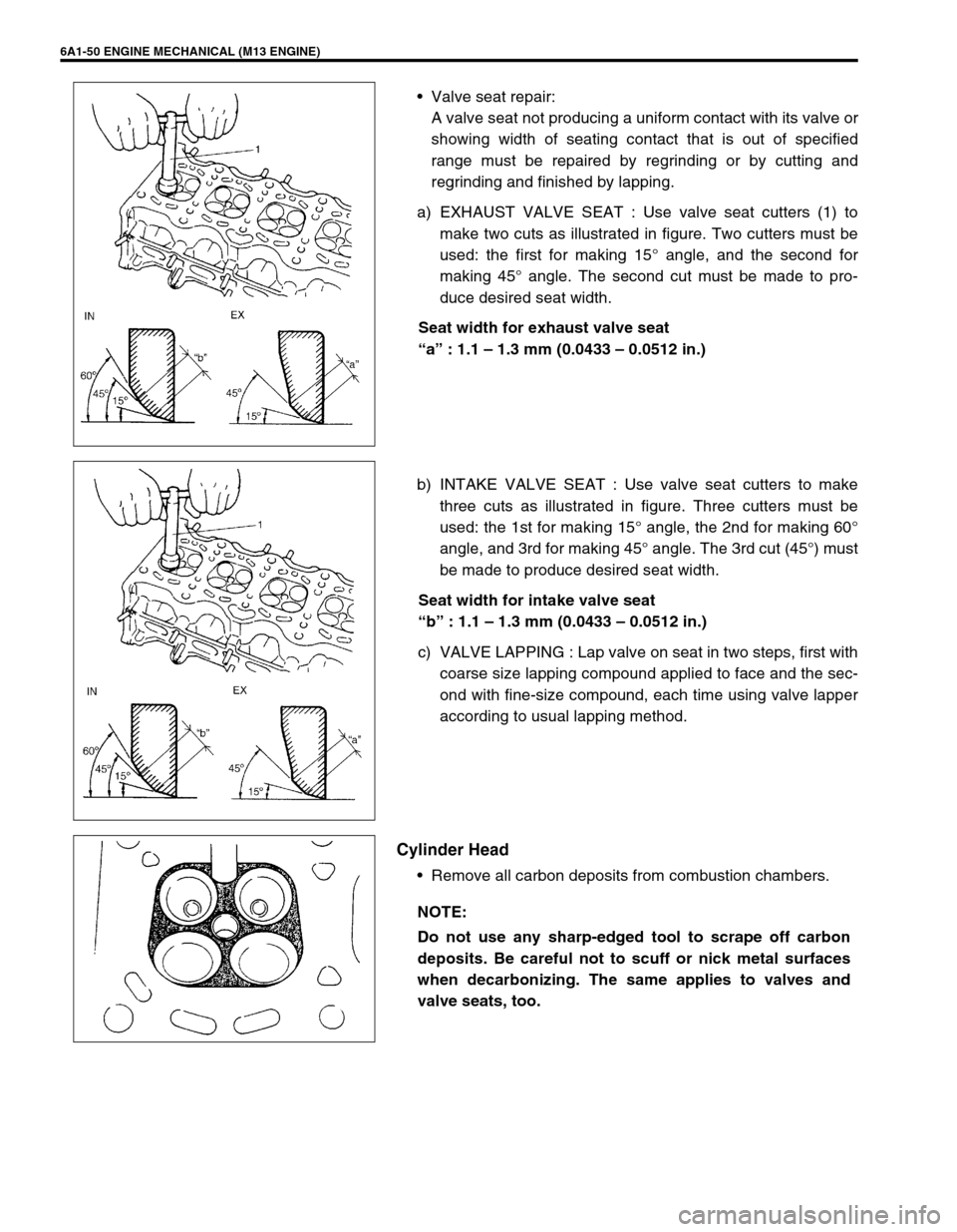
Valve seat repair:
A valve seat not producing a uniform contact with its valve or
showing width of seating contact that is out of specified
range must be repaired by regrinding or by cutting and
regrinding and finished by lapping.
a) EXHAUST VALVE SEAT : Use valve seat cutters (1) to
make two cuts as illustrated in figure. Two cutters must be
used: the first for making 15° angle, and the second for
making 45° angle. The second cut must be made to pro-
duce desired seat width.
Seat width for exhaust valve seat
“a” : 1.1 – 1.3 mm (0.0433 – 0.0512 in.)
b) INTAKE VALVE SEAT : Use valve seat cutters to make
three cuts as illustrated in figure. Three cutters must be
used: the 1st for making 15° angle, the 2nd for making 60°
angle, and 3rd for making 45° angle. The 3rd cut (45°) must
be made to produce desired seat width.
Seat width for intake valve seat
“b” : 1.1 – 1.3 mm (0.0433 – 0.0512 in.)
c) VALVE LAPPING : Lap valve on seat in two steps, first with
coarse size lapping compound applied to face and the sec-
ond with fine-size compound, each time using valve lapper
according to usual lapping method.
Cylinder Head
Remove all carbon deposits from combustion chambers.
NOTE:
Do not use any sharp-edged tool to scrape off carbon
deposits. Be careful not to scuff or nick metal surfaces
when decarbonizing. The same applies to valves and
valve seats, too.
Page 552 of 698
ENGINE MECHANICAL (M13 ENGINE) 6A1-51
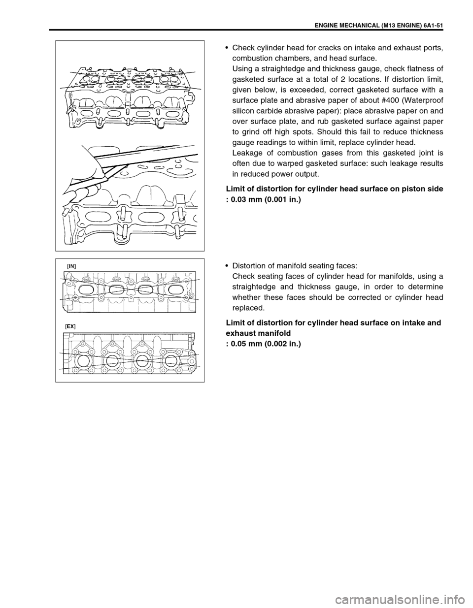
Check cylinder head for cracks on intake and exhaust ports,
combustion chambers, and head surface.
Using a straightedge and thickness gauge, check flatness of
gasketed surface at a total of 2 locations. If distortion limit,
given below, is exceeded, correct gasketed surface with a
surface plate and abrasive paper of about #400 (Waterproof
silicon carbide abrasive paper): place abrasive paper on and
over surface plate, and rub gasketed surface against paper
to grind off high spots. Should this fail to reduce thickness
gauge readings to within limit, replace cylinder head.
Leakage of combustion gases from this gasketed joint is
often due to warped gasketed surface: such leakage results
in reduced power output.
Limit of distortion for cylinder head surface on piston side
: 0.03 mm (0.001 in.)
Distortion of manifold seating faces:
Check seating faces of cylinder head for manifolds, using a
straightedge and thickness gauge, in order to determine
whether these faces should be corrected or cylinder head
replaced.
Limit of distortion for cylinder head surface on intake and
exhaust manifold
: 0.05 mm (0.002 in.)
Page 553 of 698
6A1-52 ENGINE MECHANICAL (M13 ENGINE)
Valve Springs
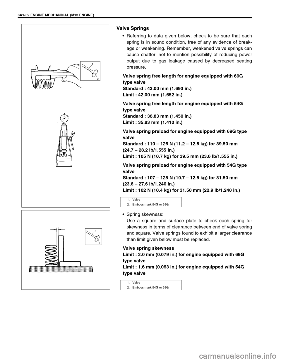
Referring to data given below, check to be sure that each
spring is in sound condition, free of any evidence of break-
age or weakening. Remember, weakened valve springs can
cause chatter, not to mention possibility of reducing power
output due to gas leakage caused by decreased seating
pressure.
Valve spring free length for engine equipped with 69G
type valve
Standard : 43.00 mm (1.693 in.)
Limit : 42.00 mm (1.652 in.)
Valve spring free length for engine equipped with 54G
type valve
Standard : 36.83 mm (1.450 in.)
Limit : 35.83 mm (1.410 in.)
Valve spring preload for engine equipped with 69G type
valve
Standard : 110 – 126 N (11.2 – 12.8 kg) for 39.50 mm
(24.7 – 28.2 lb/1.555 in.)
Limit : 105 N (10.7 kg) for 39.5 mm (23.6 lb/1.555 in.)
Valve spring preload for engine equipped with 54G type
valve
Standard : 107 – 125 N (10.7 – 12.5 kg) for 31.50 mm
(23.6 – 27.6 lb/1.240 in.)
Limit : 102 N (10.4 kg) for 31.50 mm (22.9 lb/1.240 in.)
Spring skewness:
Use a square and surface plate to check each spring for
skewness in terms of clearance between end of valve spring
and square. Valve springs found to exhibit a larger clearance
than limit given below must be replaced.
Valve spring skewness
Limit : 2.0 mm (0.079 in.) for engine equipped with 69G
type valve
Limit : 1.6 mm (0.063 in.) for engine equipped with 54G
type valve
1. Valve
2. Emboss mark 54G or 69G
1. Valve
2. Emboss mark 54G or 69G
Page 554 of 698
ENGINE MECHANICAL (M13 ENGINE) 6A1-53
ASSEMBLY
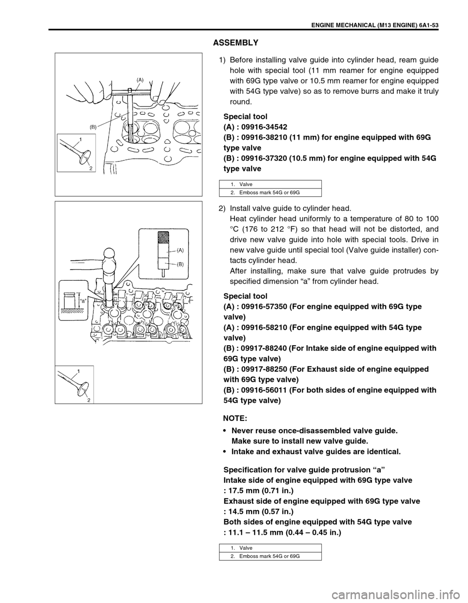
1) Before installing valve guide into cylinder head, ream guide
hole with special tool (11 mm reamer for engine equipped
with 69G type valve or 10.5 mm reamer for engine equipped
with 54G type valve) so as to remove burrs and make it truly
round.
Special tool
(A) : 09916-34542
(B) : 09916-38210 (11 mm) for engine equipped with 69G
type valve
(B) : 09916-37320 (10.5 mm) for engine equipped with 54G
type valve
2) Install valve guide to cylinder head.
Heat cylinder head uniformly to a temperature of 80 to 100
°C (176 to 212 °F) so that head will not be distorted, and
drive new valve guide into hole with special tools. Drive in
new valve guide until special tool (Valve guide installer) con-
tacts cylinder head.
After installing, make sure that valve guide protrudes by
specified dimension “a” from cylinder head.
Special tool
(A) : 09916-57350 (For engine equipped with 69G type
valve)
(A) : 09916-58210 (For engine equipped with 54G type
valve)
(B) : 09917-88240 (For Intake side of engine equipped with
69G type valve)
(B) : 09917-88250 (For Exhaust side of engine equipped
with 69G type valve)
(B) : 09916-56011 (For both sides of engine equipped with
54G type valve)
Specification for valve guide protrusion “a”
Intake side of engine equipped with 69G type valve
: 17.5 mm (0.71 in.)
Exhaust side of engine equipped with 69G type valve
: 14.5 mm (0.57 in.)
Both sides of engine equipped with 54G type valve
: 11.1 – 11.5 mm (0.44 – 0.45 in.)
1. Valve
2. Emboss mark 54G or 69G
NOTE:
Never reuse once-disassembled valve guide.
Make sure to install new valve guide.
Intake and exhaust valve guides are identical.
1. Valve
2. Emboss mark 54G or 69G
Page 555 of 698
6A1-54 ENGINE MECHANICAL (M13 ENGINE)
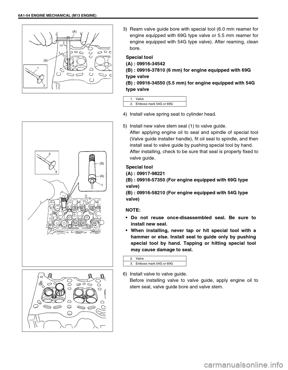
3) Ream valve guide bore with special tool (6.0 mm reamer for
engine equipped with 69G type valve or 5.5 mm reamer for
engine equipped with 54G type valve). After reaming, clean
bore.
Special tool
(A) : 09916-34542
(B) : 09916-37810 (6 mm) for engine equipped with 69G
type valve
(B) : 09916-34550 (5.5 mm) for engine equipped with 54G
type valve
4) Install valve spring seat to cylinder head.
5) Install new valve stem seal (1) to valve guide.
After applying engine oil to seal and spindle of special tool
(Valve guide installer handle), fit oil seal to spindle, and then
install seal to valve guide by pushing special tool by hand.
After installing, check to be sure that seal is properly fixed to
valve guide.
Special tool
(A) : 09917-98221
(B) : 09916-57350 (For engine equipped with 69G type
valve)
(B) : 09916-58210 (For engine equipped with 54G type
valve)
6) Install valve to valve guide.
Before installing valve to valve guide, apply engine oil to
stem seal, valve guide bore and valve stem.
1. Valve
2. Emboss mark 54G or 69G
NOTE:
Do not reuse once-disassembled seal. Be sure to
install new seal.
When installing, never tap or hit special tool with a
hammer or else. Install seal to guide only by pushing
special tool by hand. Tapping or hitting special tool
may cause damage to seal.
2. Valve
3. Emboss mark 54G or 69G
Page 556 of 698
ENGINE MECHANICAL (M13 ENGINE) 6A1-55
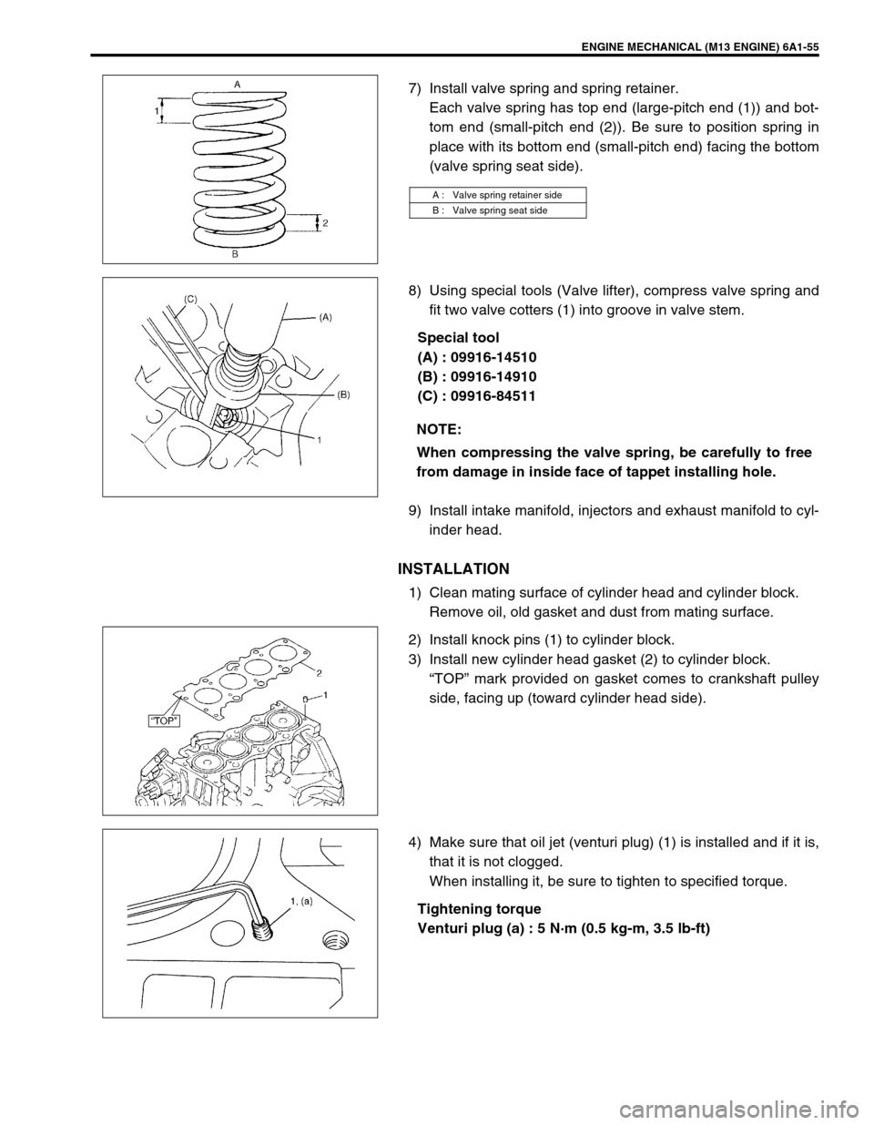
7) Install valve spring and spring retainer.
Each valve spring has top end (large-pitch end (1)) and bot-
tom end (small-pitch end (2)). Be sure to position spring in
place with its bottom end (small-pitch end) facing the bottom
(valve spring seat side).
8) Using special tools (Valve lifter), compress valve spring and
fit two valve cotters (1) into groove in valve stem.
Special tool
(A) : 09916-14510
(B) : 09916-14910
(C) : 09916-84511
9) Install intake manifold, injectors and exhaust manifold to cyl-
inder head.
INSTALLATION
1) Clean mating surface of cylinder head and cylinder block.
Remove oil, old gasket and dust from mating surface.
2) Install knock pins (1) to cylinder block.
3) Install new cylinder head gasket (2) to cylinder block.
“TOP” mark provided on gasket comes to crankshaft pulley
side, facing up (toward cylinder head side).
4) Make sure that oil jet (venturi plug) (1) is installed and if it is,
that it is not clogged.
When installing it, be sure to tighten to specified torque.
Tightening torque
Venturi plug (a) : 5 N·m (0.5 kg-m, 3.5 lb-ft)
A : Valve spring retainer side
B : Valve spring seat side
NOTE:
When compressing the valve spring, be carefully to free
from damage in inside face of tappet installing hole.
Page 557 of 698
6A1-56 ENGINE MECHANICAL (M13 ENGINE)
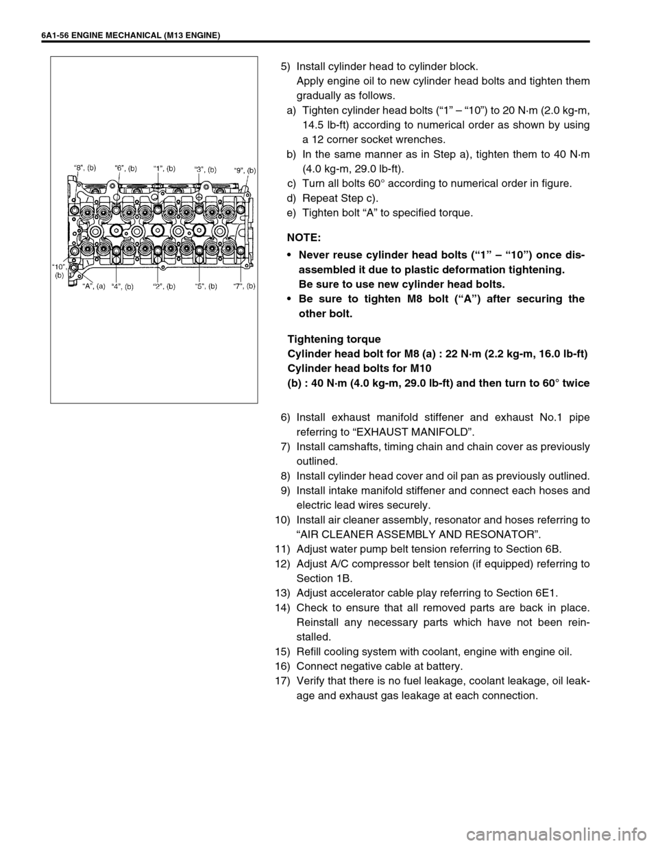
5) Install cylinder head to cylinder block.
Apply engine oil to new cylinder head bolts and tighten them
gradually as follows.
a) Tighten cylinder head bolts (“1” – “10”) to 20 N·m (2.0 kg-m,
14.5 lb-ft) according to numerical order as shown by using
a 12 corner socket wrenches.
b) In the same manner as in Step a), tighten them to 40 N·m
(4.0 kg-m, 29.0 lb-ft).
c) Turn all bolts 60° according to numerical order in figure.
d) Repeat Step c).
e) Tighten bolt “A” to specified torque.
Tightening torque
Cylinder head bolt for M8 (a) : 22 N·m (2.2 kg-m, 16.0 lb-ft)
Cylinder head bolts for M10
(b) : 40 N·m (4.0 kg-m, 29.0 lb-ft) and then turn to 60° twice
6) Install exhaust manifold stiffener and exhaust No.1 pipe
referring to “EXHAUST MANIFOLD”.
7) Install camshafts, timing chain and chain cover as previously
outlined.
8) Install cylinder head cover and oil pan as previously outlined.
9) Install intake manifold stiffener and connect each hoses and
electric lead wires securely.
10) Install air cleaner assembly, resonator and hoses referring to
“AIR CLEANER ASSEMBLY AND RESONATOR”.
11) Adjust water pump belt tension referring to Section 6B.
12) Adjust A/C compressor belt tension (if equipped) referring to
Section 1B.
13) Adjust accelerator cable play referring to Section 6E1.
14) Check to ensure that all removed parts are back in place.
Reinstall any necessary parts which have not been rein-
stalled.
15) Refill cooling system with coolant, engine with engine oil.
16) Connect negative cable at battery.
17) Verify that there is no fuel leakage, coolant leakage, oil leak-
age and exhaust gas leakage at each connection. NOTE:
Never reuse cylinder head bolts (“1” – “10”) once dis-
assembled it due to plastic deformation tightening.
Be sure to use new cylinder head bolts.
Be sure to tighten M8 bolt (“A”) after securing the
other bolt.
Page 558 of 698
ENGINE MECHANICAL (M13 ENGINE) 6A1-57
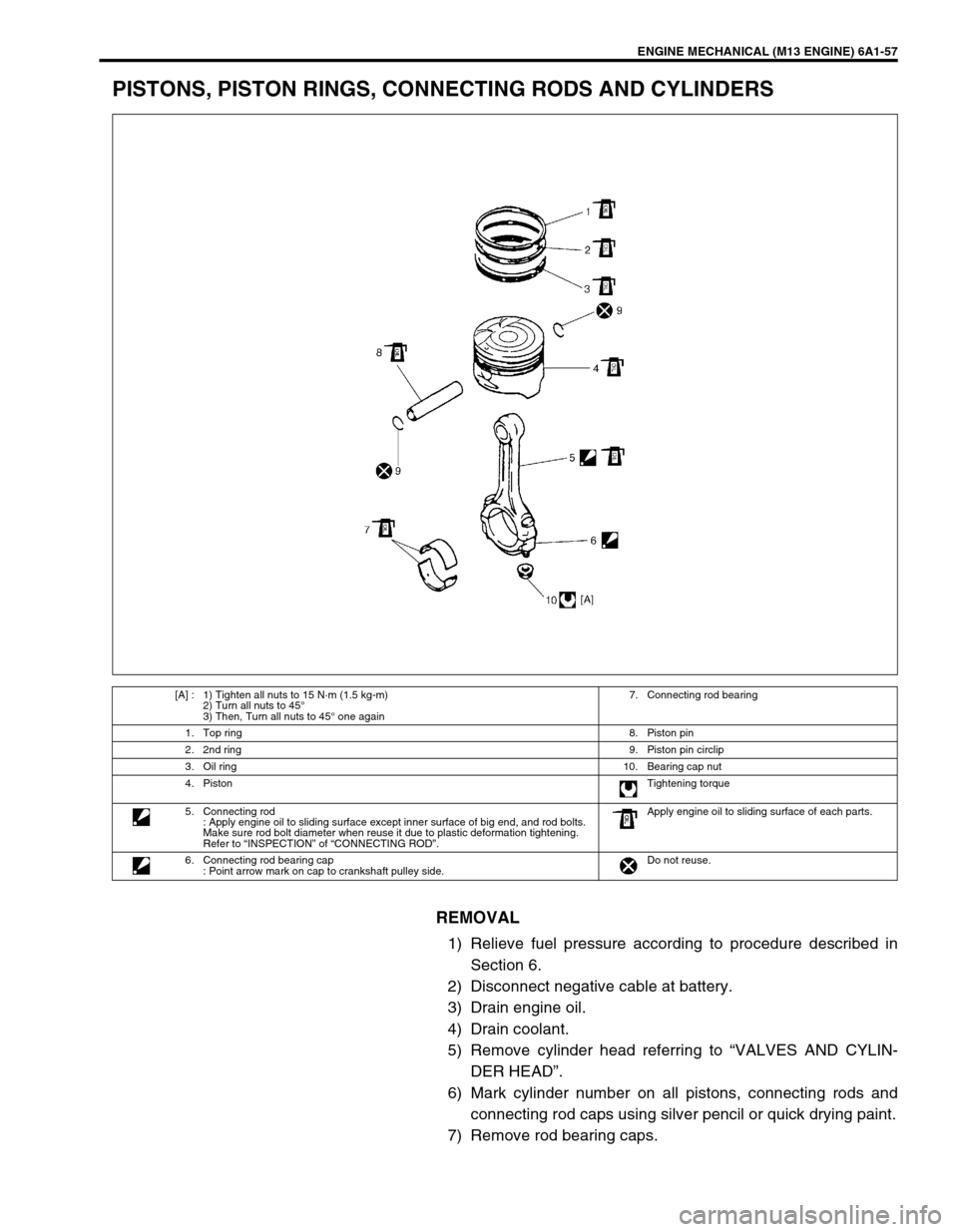
PISTONS, PISTON RINGS, CONNECTING RODS AND CYLINDERS
REMOVAL
1) Relieve fuel pressure according to procedure described in
Section 6.
2) Disconnect negative cable at battery.
3) Drain engine oil.
4) Drain coolant.
5) Remove cylinder head referring to “VALVES AND CYLIN-
DER HEAD”.
6) Mark cylinder number on all pistons, connecting rods and
connecting rod caps using silver pencil or quick drying paint.
7) Remove rod bearing caps.
[A] : 1) Tighten all nuts to 15 N·m (1.5 kg-m)
2) Turn all nuts to 45°
3) Then, Turn all nuts to 45° one again7. Connecting rod bearing
1. Top ring8. Piston pin
2. 2nd ring9. Piston pin circlip
3. Oil ring10. Bearing cap nut
4. PistonTightening torque
5. Connecting rod
: Apply engine oil to sliding surface except inner surface of big end, and rod bolts.
Make sure rod bolt diameter when reuse it due to plastic deformation tightening.
Refer to “INSPECTION” of “CONNECTING ROD”.Apply engine oil to sliding surface of each parts.
6. Connecting rod bearing cap
: Point arrow mark on cap to crankshaft pulley side.Do not reuse.
Page 559 of 698
6A1-58 ENGINE MECHANICAL (M13 ENGINE)
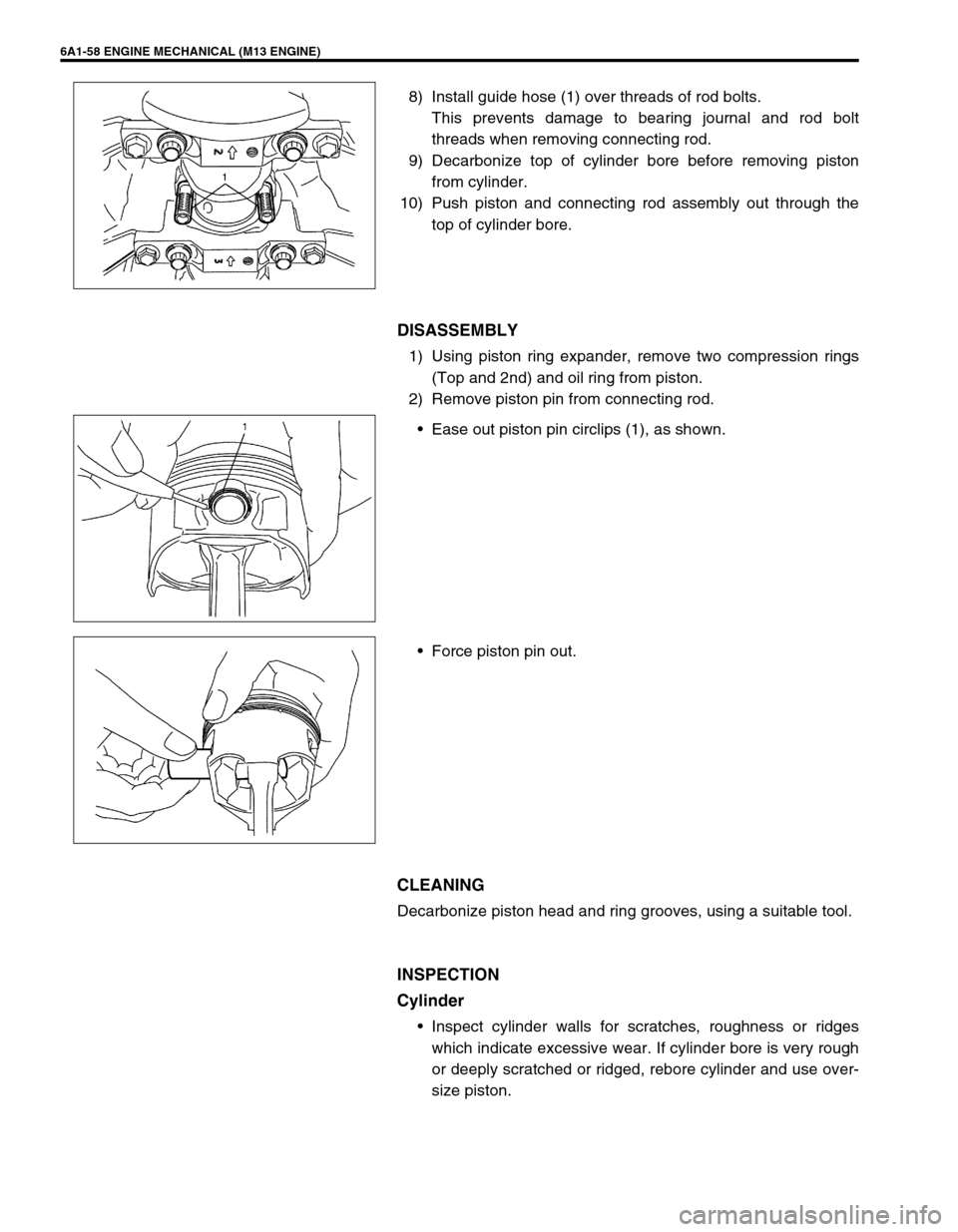
8) Install guide hose (1) over threads of rod bolts.
This prevents damage to bearing journal and rod bolt
threads when removing connecting rod.
9) Decarbonize top of cylinder bore before removing piston
from cylinder.
10) Push piston and connecting rod assembly out through the
top of cylinder bore.
DISASSEMBLY
1) Using piston ring expander, remove two compression rings
(Top and 2nd) and oil ring from piston.
2) Remove piston pin from connecting rod.
Ease out piston pin circlips (1), as shown.
Force piston pin out.
CLEANING
Decarbonize piston head and ring grooves, using a suitable tool.
INSPECTION
Cylinder
Inspect cylinder walls for scratches, roughness or ridges
which indicate excessive wear. If cylinder bore is very rough
or deeply scratched or ridged, rebore cylinder and use over-
size piston.
Page 560 of 698
ENGINE MECHANICAL (M13 ENGINE) 6A1-59
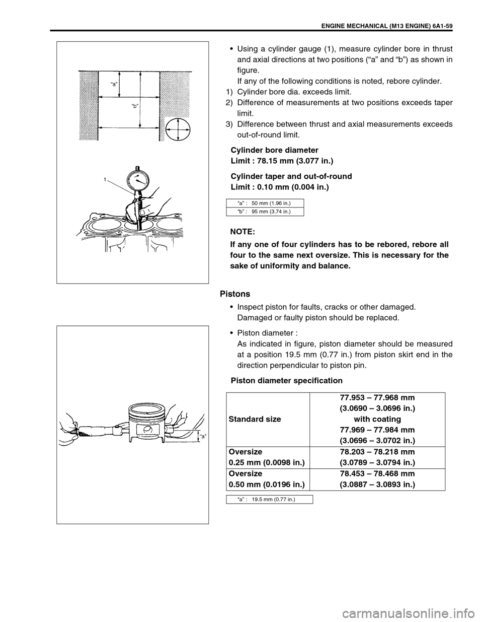
Using a cylinder gauge (1), measure cylinder bore in thrust
and axial directions at two positions (“a” and “b”) as shown in
figure.
If any of the following conditions is noted, rebore cylinder.
1) Cylinder bore dia. exceeds limit.
2) Difference of measurements at two positions exceeds taper
limit.
3) Difference between thrust and axial measurements exceeds
out-of-round limit.
Cylinder bore diameter
Limit : 78.15 mm (3.077 in.)
Cylinder taper and out-of-round
Limit : 0.10 mm (0.004 in.)
Pistons
Inspect piston for faults, cracks or other damaged.
Damaged or faulty piston should be replaced.
Piston diameter :
As indicated in figure, piston diameter should be measured
at a position 19.5 mm (0.77 in.) from piston skirt end in the
direction perpendicular to piston pin.
Piston diameter specification
“a” : 50 mm (1.96 in.)
“b” : 95 mm (3.74 in.)
NOTE:
If any one of four cylinders has to be rebored, rebore all
four to the same next oversize. This is necessary for the
sake of uniformity and balance.
Standard size77.953 – 77.968 mm
(3.0690 – 3.0696 in.)
with coating
77.969 – 77.984 mm
(3.0696 – 3.0702 in.)
Oversize
0.25 mm (0.0098 in.)78.203 – 78.218 mm
(3.0789 – 3.0794 in.)
Oversize
0.50 mm (0.0196 in.)78.453 – 78.468 mm
(3.0887 – 3.0893 in.)
“a” : 19.5 mm (0.77 in.)