lock SUZUKI SWIFT 2000 1.G Transmission Service Service Manual
[x] Cancel search | Manufacturer: SUZUKI, Model Year: 2000, Model line: SWIFT, Model: SUZUKI SWIFT 2000 1.GPages: 447, PDF Size: 10.54 MB
Page 114 of 447

7B-72 AUTOMATIC TRANSMISSION (4 A/T)
When ignition switch is turned “ON” and brake pedal is
depressed, selector lever can be shifted from “P” range posi-
tion to any other range.
3) With ignition lever shifted to any position other than “P”
range, check that ignition key cannot be turned “LOCK” posi-
tion and it cannot be removed from ignition switch unless it is
at “LOCK” position.
KEY INTERLOCK CABLE (IF EQUIPPED)
1. selector lever 3. key inter lock cable
2. knob button 4. key cylinder
NOTE:
Don’t bend interlock cable excessively when removing and installing it, or system will not operate
correctly.
Page 115 of 447

AUTOMATIC TRANSMISSION (4 A/T) 7B-73
REMOVAL
1) Disconnect negative cable at battery and disable air bag sys-
tem, referring to “DISABLING AIR BAG SYSTEMS” in Sec-
tion 10B (if equipped).
2) Remove steering column hole cover and steering column
cover.
3) Remove steering column mounting bolts and nuts.
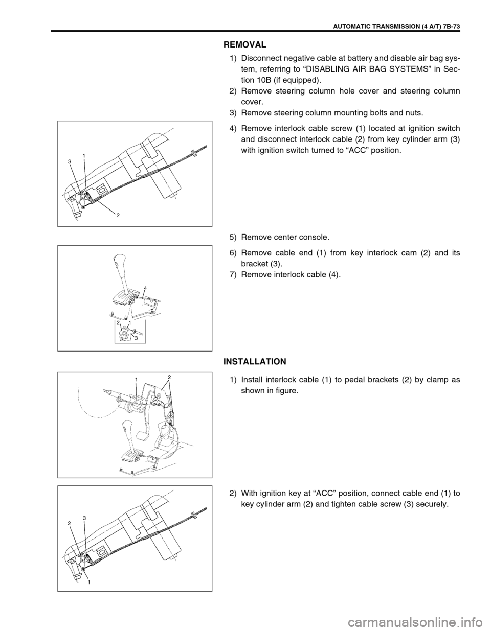
4) Remove interlock cable screw (1) located at ignition switch
and disconnect interlock cable (2) from key cylinder arm (3)
with ignition switch turned to “ACC” position.
5) Remove center console.
6) Remove cable end (1) from key interlock cam (2) and its
bracket (3).
7) Remove interlock cable (4).
INSTALLATION
1) Install interlock cable (1) to pedal brackets (2) by clamp as
shown in figure.
2) With ignition key at “ACC” position, connect cable end (1) to
key cylinder arm (2) and tighten cable screw (3) securely.
Page 116 of 447

7B-74 AUTOMATIC TRANSMISSION (4 A/T)
3) If selector lever is in “P” range, shift selector lever to other
than “P” range with releasing shift lock referring to “SHIFT
LOCK SOLENOID MANUAL RELEASE” in this section.
4) Install cable end (1) and cable casing cap (2) to key interlock
cam (3) and its bracket (4), then install cable (5) to selector
pad (6).
5) With selector lever set at “P” position, turn ignition key to
“ACC” position and then check for following conditions.
With knob button released, ignition key can be turned from
“ACC” position to “LOCK” position.
With knob button pressed, ignition key cannot be turned from
“ACC” position to “LOCK” position.
6) Install steering column referring to Section 3C.
7) Install steering column hole cover.
8) Install center console.
9) Connect negative cable at battery and enable air bag sys-
tem, referring to “ENABLING AIR BAG SYSTEM” in Section
10B (if equipped).
Page 118 of 447

7B-76 AUTOMATIC TRANSMISSION (4 A/T)
DISMOUNTING
1) Take down transmission with engine. For its procedure, refer
to Section 6A1.
2) For 4WD vehicle, remove transfer referring to Section 7D
For 2WD vehicle, remove engine rear mounting No.1
bracket and engine rear mounting No.2 bracket with stiff-
ener.
3) Remove torque converter housing lower plate (1).
4) Remove drive plate bolts.
To lock drive plate (1), engage a flat head rod or the like (2)
with drive plate gear.
5) Remove starting motor.
6) Remove bolts and nut fastening engine and transmission,
then detach transmission from engine.
NOTE:
When detaching transmission from engine, move it in
parallel with crankshaft and use care so as not to apply
excessive force to drive plate and torque converter.
WARNING:
Be sure to keep transmission with torque converter hori-
zontal or facing up throughout the work. Should it be
tilted with torque converter down, converter may fall off
and cause personal injury.
Page 119 of 447

AUTOMATIC TRANSMISSION (4 A/T) 7B-77
REMOUNTING
1) Make sure that torque converter is installed correctly to
transmission.
Refer to “UNIT ASSEMBLY” in this section.
2) Attach transmission to engine.
Tightening torque
Transmission to engine bolts and nut
(a) : 85 N·m (8.5 kg-m, 61.5 lb-ft)
3) Tighten drive plate-torque converter bolts.
Align drive plate bolt hole and torque converter through
starter motor mounting opening then tighten bolts through
torque converter housing lower plate opening.
Lock drive plate (1) by engaging a flat head rod or the like (2)
with drive plate gear.
Tightening torque
Drive plate to torque converter bolts
(a) : 20 N·m (2.0 kg-m, 14.5 lb-ft)
4) Install torque converter housing lower plate (1).
5) Install starter motor.
Tightening Torque
Starter motor bolts : 23 N·m (2.3 kg-m, 16.5 lb-ft)
6) For 4WD vehicle, install transfer referring to Section 7D.
For 2WD vehicle, install engine rear mounting brackets and
stiffener.
7) Remount engine with transmission assembly to vehicle.
Refer to Section 6A1 for its procedure. WARNING:
Be sure to keep transmission with torque converter hori-
zontal or facing up throughout the work. Should it be
tilted with torque converter down, converter may fall off
and cause personal injury.
3. Wrench
4. Engine oil pan
Page 124 of 447

7B-82 AUTOMATIC TRANSMISSION (4 A/T)
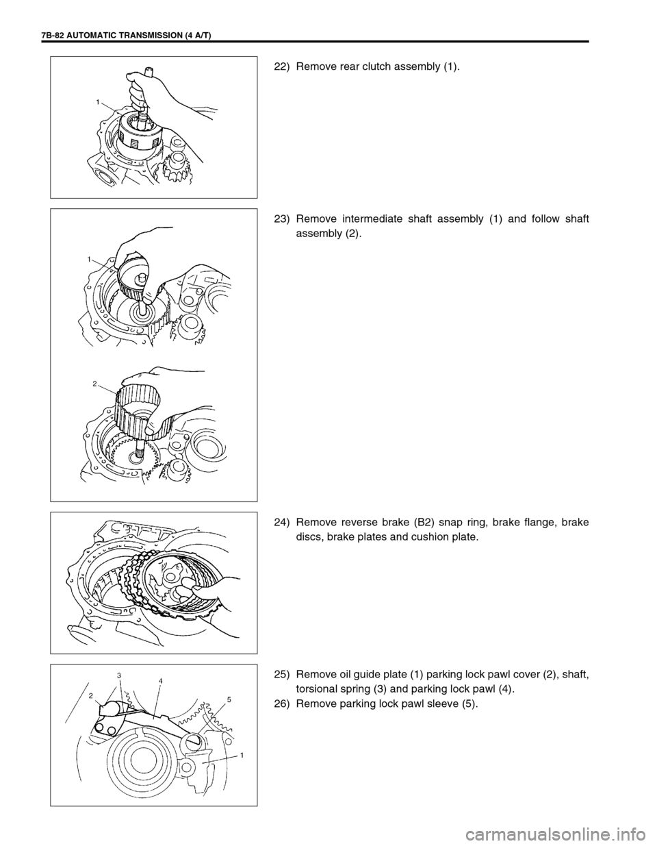
22) Remove rear clutch assembly (1).
23) Remove intermediate shaft assembly (1) and follow shaft
assembly (2).
24) Remove reverse brake (B2) snap ring, brake flange, brake
discs, brake plates and cushion plate.
25) Remove oil guide plate (1) parking lock pawl cover (2), shaft,
torsional spring (3) and parking lock pawl (4).
26) Remove parking lock pawl sleeve (5).
Page 125 of 447

AUTOMATIC TRANSMISSION (4 A/T) 7B-83
27) Remove counter driven gear assembly (1) and thrust needle
roller bearing (2).
28) Remove control shift lever (1), nuts (2), washer (3) from
manual shift shaft (4).
29) Remove detent spring (1).
30) Remove manual shift shaft (1) with parking lock rod (2), and
washer (3) from transmission case.
Page 148 of 447

7B-106 AUTOMATIC TRANSMISSION (4 A/T)
VALVE BODY
1. Upper valve body 12. Lock-up control valve 23. Fail valve No.1
2. Upper valve body gasket 13. Lock-up control valve spring 24. Fail valve No.1 sleeve
3. Valve body plate 14. Lock-up signal valve plug 25. Key (short)
4. Lower valve body gasket 15. Lock-up signal valve 26. Key (long)
5. Lower valve body 16. Lock-up signal valve spring 27. Oil strainer
6. Primary regulator valve sleeve 17. Fail valve No.2 sleeve 28. Cooler by-pass valve
7. Primary regulator valve plunger 18. Fail valve No.2 29. Cooler by-pass valve spring
8. Primary regulator valve spring 19. Secondary regulator valve plug 30. Steel ball
9. Washer 20. Secondary regulator valve spring 31. Lock-up control valve
10. Primary regulator valve 21. Secondary regulator valve Apply automatic transmission fluid.
11. Lock-up control valve sleeve 22. Manual valve Do not reuse.
Page 150 of 447

7B-108 AUTOMATIC TRANSMISSION (4 A/T)
Valve spring dimensions (Reference)
Lower Valve Body
1) Remove oil strainers (1).
2) Remove solenoid valves, if still attached.
3) Remove keys (2) and pull out all sleeve, plug, spring and
valves.
Valve spring dimensions (Reference)Spring Free length
“a” (mm)Outside diameter
“b” (mm)
Primary regula-
tor valve spring79.2 18.0
Lock-up control
valve spring31.1 8.5
Lock-up signal
valve spring36.1 8.5
3. Fail valve No.1 sleeve
4. Fail valve No.1
5. Cooler by-pass valve
6. Cooler by-pass valve spring
7. Manual valve
8. Secondary regulator valve
9. Secondary regulator valve spring
10. Secondary regulator valve plug
Spring Free length
“a” (mm)Outside diame-
ter “b” (mm)
Secondary regula-
tor valve spring38.7 8.8
Cooler by-pass
valve spring22.8 8.0
Page 151 of 447

AUTOMATIC TRANSMISSION (4 A/T) 7B-109
ASSEMBLY
Upper Valve Body
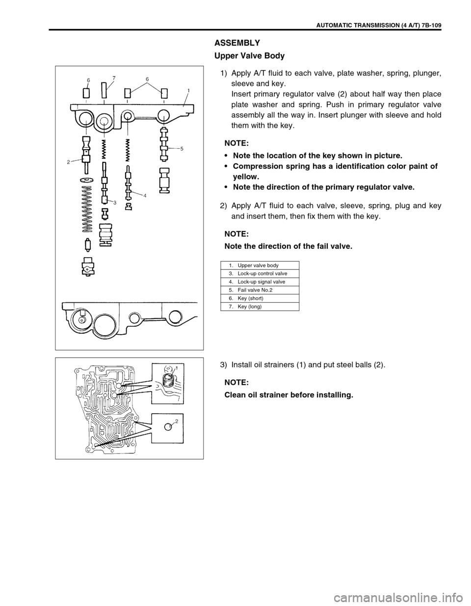
1) Apply A/T fluid to each valve, plate washer, spring, plunger,
sleeve and key.
Insert primary regulator valve (2) about half way then place
plate washer and spring. Push in primary regulator valve
assembly all the way in. Insert plunger with sleeve and hold
them with the key.
2) Apply A/T fluid to each valve, sleeve, spring, plug and key
and insert them, then fix them with the key.
3) Install oil strainers (1) and put steel balls (2).NOTE:
Note the location of the key shown in picture.
Compression spring has a identification color paint of
yellow.
Note the direction of the primary regulator valve.
NOTE:
Note the direction of the fail valve.
1. Upper valve body
3. Lock-up control valve
4. Lock-up signal valve
5. Fail valve No.2
6. Key (short)
7. Key (long)
NOTE:
Clean oil strainer before installing.