troubleshooting SUZUKI SWIFT 2008 2.G Service Workshop Manual
[x] Cancel search | Manufacturer: SUZUKI, Model Year: 2008, Model line: SWIFT, Model: SUZUKI SWIFT 2008 2.GPages: 1496, PDF Size: 34.44 MB
Page 909 of 1496
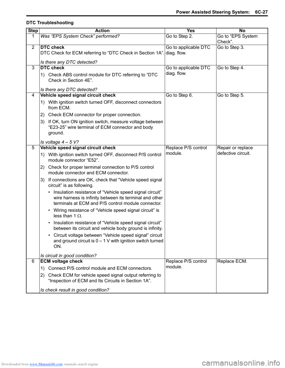
Downloaded from www.Manualslib.com manuals search engine Power Assisted Steering System: 6C-27
DTC TroubleshootingStep Action Yes No 1 Was “EPS System Check” performed? Go to Step 2. Go to “EPS System
Check”.
2 DTC check
DTC Check for ECM referring to “DTC Check in Section 1A”.
Is there any DTC detected? Go to applicable DTC
diag. flow.
Go to Step 3.
3 DTC check
1) Check ABS control module for DTC referring to “DTC
Check in Section 4E”.
Is there any DTC detected? Go to applicable DTC
diag. flow.
Go to Step 4.
4 Vehicle speed signal circuit check
1) With ignition switch turned OFF, disconnect connectors
from ECM.
2) Check ECM connector for proper connection.
3) If OK, turn ON ignition switch, measure voltage between “E23-25” wire terminal of ECM connector and body
ground.
Is voltage 4 – 5 V? Go to Step 6.
Go to Step 5.
5 Vehicle speed signal circuit check
1) With ignition switch turned OFF, disconnect P/S control
module connector “E52”.
2) Check for proper terminal connection to P/S control module connector and ECM connector.
3) If connections are OK, chec k that “Vehicle speed signal
circuit” is as following.
• Insulation resistance of “Vehicle speed signal circuit” wire harness is infinity between its terminal and other
terminals at ECM and P/S control module connector.
• Wiring resistance of “Vehicle speed signal circuit” is less than 1 Ω.
• Insulation resistance of “Vehicle speed signal circuit” between its circuit and vehicle body ground is infinity.
• Circuit voltage between “Vehicle speed signal” circuit and ground circuit is 0 – 1 V with ignition switch turned
ON.
Is circuit in good condition? Replace P/S control
module.
Repair or replace
defective circuit.
6 ECM voltage check
1) Connect P/S control mo dule and ECM connectors.
2) Check ECM for vehicle speed signal output referring to “Inspection of ECM and Its Circuits in Section 1A”.
Is check result in good condition? Replace P/S control
module.
Replace ECM.
Page 911 of 1496
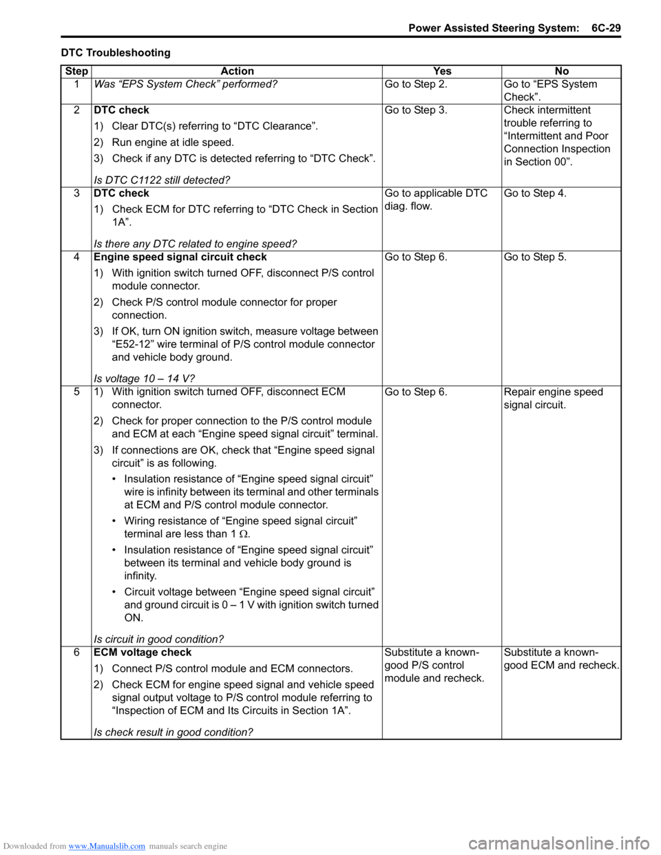
Downloaded from www.Manualslib.com manuals search engine Power Assisted Steering System: 6C-29
DTC TroubleshootingStep Action Yes No 1 Was “EPS System Check” performed? Go to Step 2. Go to “EPS System
Check”.
2 DTC check
1) Clear DTC(s) referring to “DTC Clearance”.
2) Run engine at idle speed.
3) Check if any DTC is detecte d referring to “DTC Check”.
Is DTC C1122 still detected? Go to Step 3. Check intermittent
trouble referring to
“Intermittent and Poor
Connection Inspection
in Section 00”.
3 DTC check
1) Check ECM for DTC referring to “DTC Check in Section
1A”.
Is there any DTC related to engine speed? Go to applicable DTC
diag. flow.
Go to Step 4.
4 Engine speed signal circuit check
1) With ignition switch turned OFF, disconnect P/S control
module connector.
2) Check P/S control module connector for proper connection.
3) If OK, turn ON ignition switch, measure voltage between “E52-12” wire terminal of P/S control module connector
and vehicle body ground.
Is voltage 10 – 14 V? Go to Step 6.
Go to Step 5.
5 1) With ignition switch turned OFF, disconnect ECM connector.
2) Check for proper connection to the P/S control module and ECM at each “Engine speed signal circuit” terminal.
3) If connections are OK, chec k that “Engine speed signal
circuit” is as following.
• Insulation resistance of “Engine speed signal circuit” wire is infinity between its terminal and other terminals
at ECM and P/S control module connector.
• Wiring resistance of “Engine speed signal circuit” terminal are less than 1 Ω.
• Insulation resistance of “Engine speed signal circuit” between its terminal and vehicle body ground is
infinity.
• Circuit voltage between “Engine speed signal circuit” and ground circuit is 0 – 1 V with ignition switch turned
ON.
Is circuit in good condition? Go to Step 6.
Repair engine speed
signal circuit.
6 ECM voltage check
1) Connect P/S control mo dule and ECM connectors.
2) Check ECM for engine speed signal and vehicle speed signal output voltage to P/S control module referring to
“Inspection of ECM and Its Circuits in Section 1A”.
Is check result in good condition? Substitute a known-
good P/S control
module and recheck.
Substitute a known-
good ECM and recheck.
Page 913 of 1496
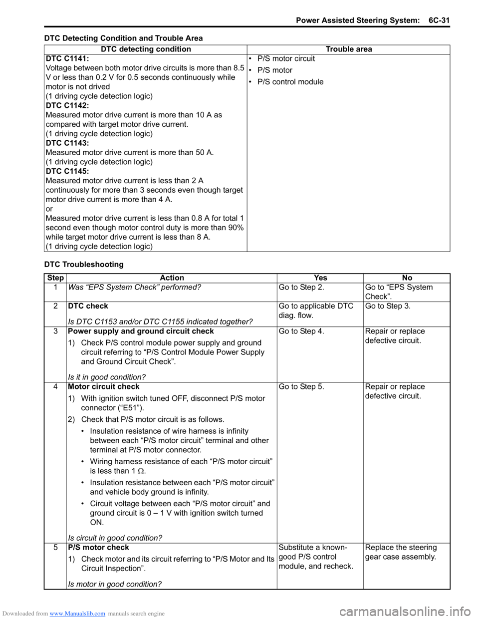
Downloaded from www.Manualslib.com manuals search engine Power Assisted Steering System: 6C-31
DTC Detecting Condition and Trouble Area
DTC TroubleshootingDTC detecting condition Trouble area
DTC C1141:
Voltage between both motor drive circuits is more than 8.5
V or less than 0.2 V for 0.5 seconds continuously while
motor is not drived
(1 driving cycle detection logic)
DTC C1142:
Measured motor drive current is more than 10 A as
compared with target motor drive current.
(1 driving cycle detection logic)
DTC C1143:
Measured motor drive current is more than 50 A.
(1 driving cycle detection logic)
DTC C1145:
Measured motor drive current is less than 2 A
continuously for more than 3 seconds even though target
motor drive current is more than 4 A.
or
Measured motor drive current is less than 0.8 A for total 1
second even though motor cont rol duty is more than 90%
while target motor drive current is less than 8 A.
(1 driving cycle detection logic) • P/S motor circuit
• P/S motor
• P/S control module
Step
Action YesNo
1 Was “EPS System Check” performed? Go to Step 2.Go to “EPS System
Check”.
2 DTC check
Is DTC C1153 and/or DTC C1155 indicated together? Go to applicable DTC
diag. flow.
Go to Step 3.
3 Power supply and ground circuit check
1) Check P/S control module power supply and ground
circuit referring to “P/S Control Module Power Supply
and Ground Circuit Check”.
Is it in good condition? Go to Step 4.
Repair or replace
defective circuit.
4 Motor circuit check
1) With ignition switch tuned OFF, disconnect P/S motor
connector (“E51”).
2) Check that P/S motor circuit is as follows. • Insulation resistance of wire harness is infinity between each “P/S motor circuit” terminal and other
terminal at P/S motor connector.
• Wiring harness resistance of each “P/S motor circuit”
is less than 1 Ω.
• Insulation resistance between each “P/S motor circuit” and vehicle body ground is infinity.
• Circuit voltage between each “P/S motor circuit” and ground circuit is 0 – 1 V with ignition switch turned
ON.
Is circuit in good condition? Go to Step 5.
Repair or replace
defective circuit.
5 P/S motor check
1) Check motor and its circuit referring to “P/S Motor and Its
Circuit Inspection”.
Is motor in good condition? Substitute a known-
good P/S control
module, and recheck.
Replace the steering
gear case assembly.
Page 914 of 1496
Downloaded from www.Manualslib.com manuals search engine 6C-32 Power Assisted Steering System:
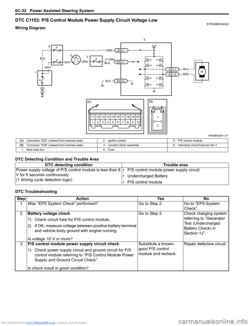
DTC C1153: P/S Control Module Power Supply Circuit Voltage LowS7RS0B6304020
Wiring Diagram
DTC Detecting Condition and Trouble Area
DTC Troubleshooting
MBLK
REDE51-1
E51-2
12V
5
[A ]
12 3
4 5 67
89
11
10
12 13
141516
17 18 19 20
[B ]
1
2
LT GRN
/BLKE52-1 E49-1
GRNGRNWHTBLK
WHY
6
3
4
4
4
4
1 2
E49-2BLK
I7RS0B630011-01
[A]: Connector “E52” (viewed from harness side)
2. Ignition switch5. P/S control module
[B]: Connector “E49” (viewed from harness side) 3. Junction block assembly 6. Individual circuit fuse box No.1
1. Main fuse box 4. Fuse
DTC detecting condition Trouble area
Power supply voltage of P/S control module is less than 9
V for 5 seconds continuously
(1 driving cycle detection logic) • P/S control module power supply circuit
• Undercharged Battery
• P/S control module
Step
Action YesNo
1 Was “EPS System Check” performed? Go to Step 2.Go to “EPS System
Check”.
2 Battery voltage check
1) Check circuit fuse for P/S control module.
2) If OK, measure voltage between positive battery terminal
and vehicle body ground with engine running.
Is voltage 10 V or more? Go to Step 3.
Check charging system
referring to “Generator
Test (Undercharged
Battery Check) in
Section 1J”.
3 P/S control module power supply circuit check
1) Check power supply circuit and ground circuit for P/S
control module referring to “P/S Control Module Power
Supply and Ground Circuit Check”.
Is check result in good condition? Substitute a known-
good P/S control
module and recheck.
Repair defective circuit.
Page 915 of 1496
Downloaded from www.Manualslib.com manuals search engine Power Assisted Steering System: 6C-33
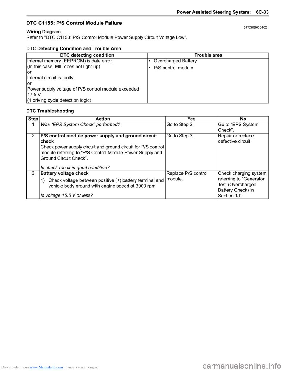
DTC C1155: P/S Control Module FailureS7RS0B6304021
Wiring Diagram
Refer to “DTC C1153: P/S Control Module Power Supply Circuit Voltage Low”.
DTC Detecting Condition and Trouble Area
DTC Troubleshooting DTC detecting condition Trouble area
Internal memory (EEPROM) is data error.
(In this case, MIL does not light up)
or
Internal circuit is faulty.
or
Power supply voltage of P/S control module exceeded
17.5 V.
(1 driving cycle detection logic) • Overcharged Battery
• P/S control module
Step
Action YesNo
1 Was “EPS System Check” performed? Go to Step 2.Go to “EPS System
Check”.
2 P/S control module power supply and ground circuit
check
Check power supply circuit and ground circuit for P/S control
module referring to “P/S Control Module Power Supply and
Ground Circuit Check”.
Is check result in good condition? Go to Step 3.
Repair or replace
defective circuit.
3 Battery voltage check
1) Check voltage between positive (+) battery terminal and
vehicle body ground with engine speed at 3000 rpm.
Is voltage 15.5 V or less? Replace P/S control
module.
Check charging system
referring to “Generator
Test (Overcharged
Battery Check) in
Section 1J”.
Page 982 of 1496
Downloaded from www.Manualslib.com manuals search engine 7B-34 Air Conditioning System: Automatic Type
Automatic Type
Precautions
A/C System CautionS7RS0B7220001
Refer to “A/C System Caution”.
Precautions in Diagnosing TroubleS7RS0B7220002
• Do not disconnect couplers from HVAC control module, battery cable from battery, HVAC control module ground
wire harness from body or main fuse before confirming diagnostic information (diagnostic trouble code) stored in
HVAC control module memory.
• Diagnostic information (diagnostic trouble code) stored in HVAC control module can be checked by display of HVAC
control module. Also, it can be checked by using SU ZUKI scan tool. Before checking diagnostic information
(diagnostic trouble code), read this manual and operator's manual for SUZUKI scan tool to know how to read
diagnostic information (diagnostic trouble code).
• When trouble is diagnosed using diagnostic information (diagnostic trouble code) on display of HVAC control
module, keep in your mind that each diagnostic inform ation (diagnostic trouble code) has priority, and only
diagnostic information (diagnostic troub le code) which has the highest priority is indicated. Therefore, after
troubleshooting the malfunction, make sure if there exists any other diagnostic information (diagnostic trouble
code).
• Be sure to read “Precautions for Electrical Circuit Service in Section 00” before inspection.
Precautions on Servicing A/C SystemS7RS0B7220003
Refer to “Precautions on Servicing A/C System”.
General Description
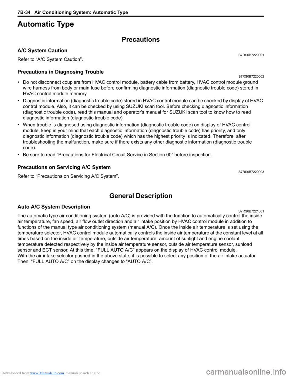
Auto A/C System DescriptionS7RS0B7221001
The automatic type air conditioning system (auto A/C) is pr ovided with the function to automatically control the inside
air temperature, fan speed, air flow outl et direction and air intake position by HVAC control module in addition to
functions of the manual type air conditioning system (manua l A/C). Once the inside air temperature is set using the
temperature selector, HVAC control module automatically controls the inside air temperature at the constant level at all
times based on the inside air temperature, outside ai r temperature, amount of sunlight and engine coolant
temperature detected respectively by the inside air te mperature sensor, outside air temperature sensor, sunload
sensor and ECT sensor. At this time, “FULL AUTO A/ C” appears on the display of HVAC control module.
With the air intake selector pushed in the above state, it is possible to select any position of the air intake actuator.
Then, “FULL AUTO A/C” on the display changes to “AUTO A/C”.
Page 991 of 1496
Downloaded from www.Manualslib.com manuals search engine Air Conditioning System: Automatic Type 7B-43
Not Using SUZUKI Scan Tool
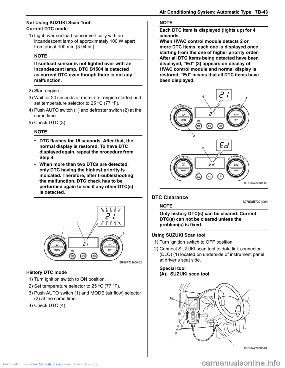
Current DTC mode1) Light over sunload sensor vertically with an incandescent lamp of approximately 100 W apart
from about 100 mm (3.94 in.).
NOTE
If sunload sensor is not lighted over with an
incandescent lamp, DTC B1504 is detected
as current DTC even though there is not any
malfunction.
2) Start engine.
3) Wait for 20 seconds or more after engine started and set temperature selector to 25 °C (77 °F).
4) Push AUTO switch (1) and defroster switch (2) at the same time.
5) Check DTC (3).
NOTE
• DTC flashes for 15 seconds. After that, the normal display is rest ored. To have DTC
displayed again, repeat the procedure from
Step 4.
• When more than two DTCs are detected, only DTC having the highest priority is
indicated. Therefore, after troubleshooting
the malfunction, DTC check has to be
performed again to see if any other DTC(s)
is detected.
History DTC mode
1) Turn ignition switch to ON position.
2) Set temperature selector to 25 °C (77 °F).
3) Push AUTO switch (1) and MODE (air flow) selector
(2) at the same time.
4) Check DTC (4).
NOTE
Each DTC item is displayed (lights up) for 4
seconds.
When HVAC control module detects 2 or
more DTC items, each one is displayed once
starting from the one of higher priority order.
After all DTC items being detected have been
displayed, “Ed” (3) appears on display of
HVAC control module and normal display is
restored. “Ed” means that all DTC items have
been displayed.
DTC ClearanceS7RS0B7224004
NOTE
Only history DTC(s) can be cleared. Current
DTC(s) can not be cleared unless the
problem(s) is fixed.
Using SUZUKI Scan tool
1) Turn ignition switch to OFF position.
2) Connect SUZUKI scan tool to data link connector (DLC) (1) located on underside of instrument panel
at driver’s seat side.
Special tool
(A): SUZUKI scan tool1
2
3
I5RS0A722006-02
1
2 34
I5RS0A722007-02
(A)
1
I5RS0A722005-01
Page 995 of 1496
Downloaded from www.Manualslib.com manuals search engine Air Conditioning System: Automatic Type 7B-47
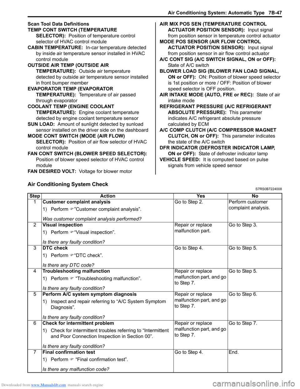
Scan Tool Data Definitions
TEMP CONT SWITCH (TEMPERATURE SELECTOR): Position of temperature control
selector of HVAC control module
CABIN TEMPERATURE: In-car temperature detected
by inside air temperature sensor installed in HVAC
control module
OUTSIDE AIR TEMP (OUTSIDE AIR TEMPERATURE): Outside air temperature
detected by outside air temperature sensor installed
in front bumper member
EVAPORATOR TEMP (EVAPORATOR TEMPERATURE): Temperature of air passed
through evaporator
COOLANT TEMP (ENGINE COOLANT TEMPERATURE): Engine coolant temperature
detected by engine coolant temperature sensor
SUN LOAD: Amount of sunlight detected by sunload
sensor installed on the driver side on the dashboard
MODE CONT SWITCH (MODE (AIR FLOW) SELECTOR): Position of air flow selector of HVAC
control module
FAN CONT SWITCH (BLOWER SPEED SELECTOR): Position of blower speed selector of HVAC control
module
FAN DESIRED VOLT: Voltage for blower motor AIR MIX POS SEN (TEMPERATURE CONTROL
ACTUATOR POSITI ON SENSOR): Input signal
from position sensor in temperature control actuator
MODE POS SENSOR (AIR FLOW CONTROL ACTUATOR POSITI ON SENSOR): Input signal
from position sensor in air flow control actuator
A/C CONT SIG (A/C SWITCH SIGNAL, ON or OFF): State of A/C switch
BLOWER LOAD SIG (BLO WER FAN LOAD SIGNAL,
ON or OFF): ON: Position of blower speed selector
is 1st position or more / OFF: Position of blower
speed selector is OFF position.
AIR INTAKE MODE (AUTO, FRE or REC): State of air
intake mode
REFRIGERANT PRESSURE (A/C REFRIGERANT ABSOLUTE PRESSURE): This parameter
indicates A/C refrigerant absolute pressure
calculated by ECM
A/C COMP CLUTCH (A/C COMPRESSOR MAGNET CLUTCH, ON or OFF): This parameter indicates
the state of the A/C switch
DFR INDICATOR (DEFROSTER INDICATOR LAMP, ON or OFF): State of defroster indicator lamp
VEHICLE SPEED: It is computed based on pulse
signals from vehicle speed sensor
Air Conditioning System CheckS7RS0B7224008
Step Action YesNo
1 Customer complaint analysis
1) Perform �)”Customer complaint analysis”.
Was customer complaint analysis performed? Go to Step 2.
Perform customer
complaint analysis.
2 Visual inspection
1) Perform �)“Visual inspection”.
Is there any faulty condition? Repair or replace
malfunction part.
Go to Step 3.
3 DTC check
1) Perform �)“DTC check”.
Is there any DTC code? Go to Step 4.
Go to Step 5.
4 Troubleshooting malfunction
1) Perform �) “Troubleshooting malfunction”.
Is there any faulty condition? Repair or replace
malfunction part, and go
to Step 7.
Go to Step 5.
5 Perform A/C system symptom diagnosis
1) Inspect and repair referri ng to “A/C System Symptom
Diagnosis”.
Is there any faulty condition? Repair or replace
malfunction part, and go
to Step 7.
Go to Step 6.
6 Check for intermittent problem
1) Check for intermittent troubles referring to “Intermittent
and Poor Connection Inspection in Section 00”.
Is there any faulty condition? Repair or replace
malfunction part, and go
to Step 7.
Go to Step 7.
7 Final confirmation test
1) Perform �) “Final confirmation test”.
Is there any malfunction code? Go to Step 4.
End.
Page 996 of 1496
Downloaded from www.Manualslib.com manuals search engine 7B-48 Air Conditioning System: Automatic Type
Description for Each Step
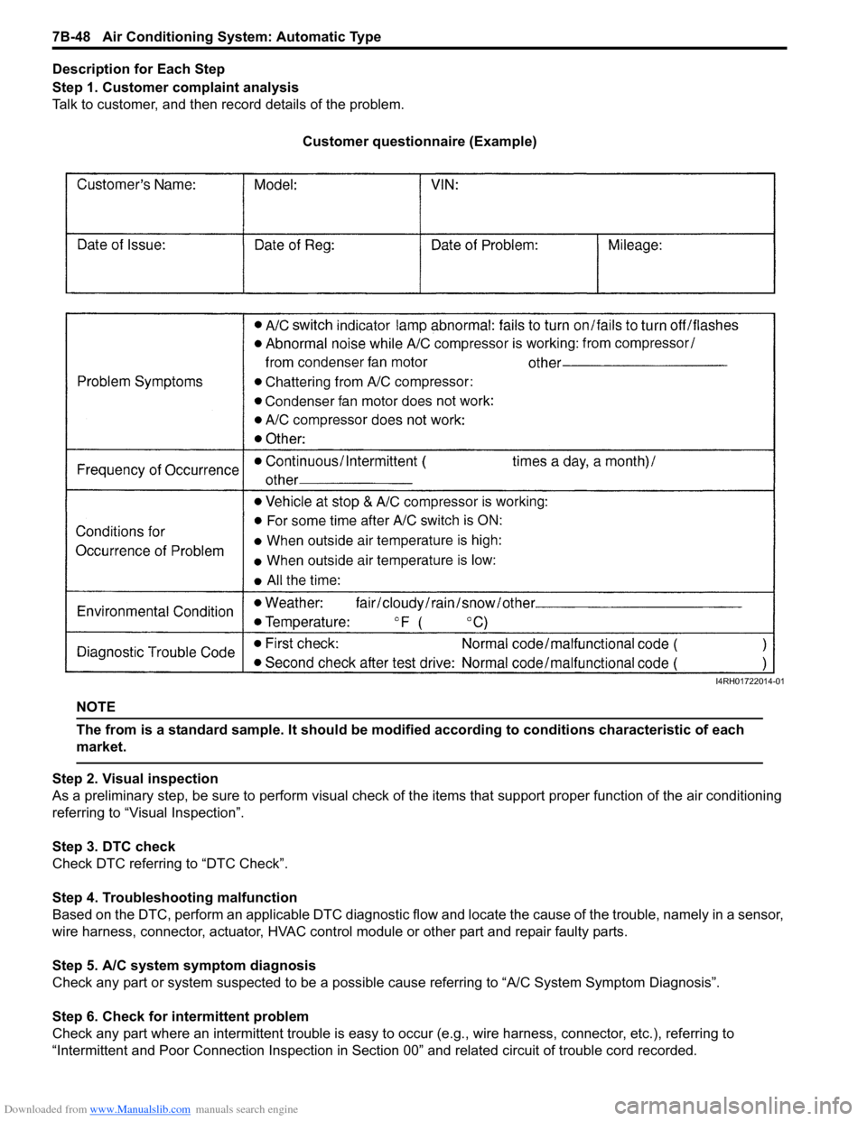
Step 1. Customer complaint analysis
Talk to customer, and then record details of the problem.
Customer questionnaire (Example)
NOTE
The from is a standard sample. It should be modified according to conditions characteristic of each
market.
Step 2. Visual inspection
As a preliminary step, be sure to perform visual check of th e items that support proper function of the air conditioning
referring to “Visual Inspection”.
Step 3. DTC check
Check DTC referring to “DTC Check”.
Step 4. Troubleshooting malfunction
Based on the DTC, perform an applicable DTC diagnostic flow and locate the cause of the trouble, namely in a sensor,
wire harness, connector, actuat or, HVAC control module or other part and repair faulty parts.
Step 5. A/C system symptom diagnosis
Check any part or system suspected to be a possible cause referring to “A/C System Symptom Diagnosis”.
Step 6. Check for intermittent problem
Check any part where an intermittent trouble is easy to oc cur (e.g., wire harness, connector, etc.), referring to
“Intermittent and Poor Connection Inspection in Sect ion 00” and related circuit of trouble cord recorded.
I4RH01722014-01
Page 997 of 1496
Downloaded from www.Manualslib.com manuals search engine Air Conditioning System: Automatic Type 7B-49
Step 7. Final confirmation test
Confirm if the problem symptom is troubleshoot and the A/C system is free from any abnormal conditions. If there
existed DTC, clear the DTC. Then , check if the DTC is still detected and if there is any other DTC.
Visual InspectionS7RS0B7224009
Check visually the following parts and systems.
DTC B1502: Inside Air Temperature Sensor and/or Its Circuit MalfunctionS7RS0B7224010
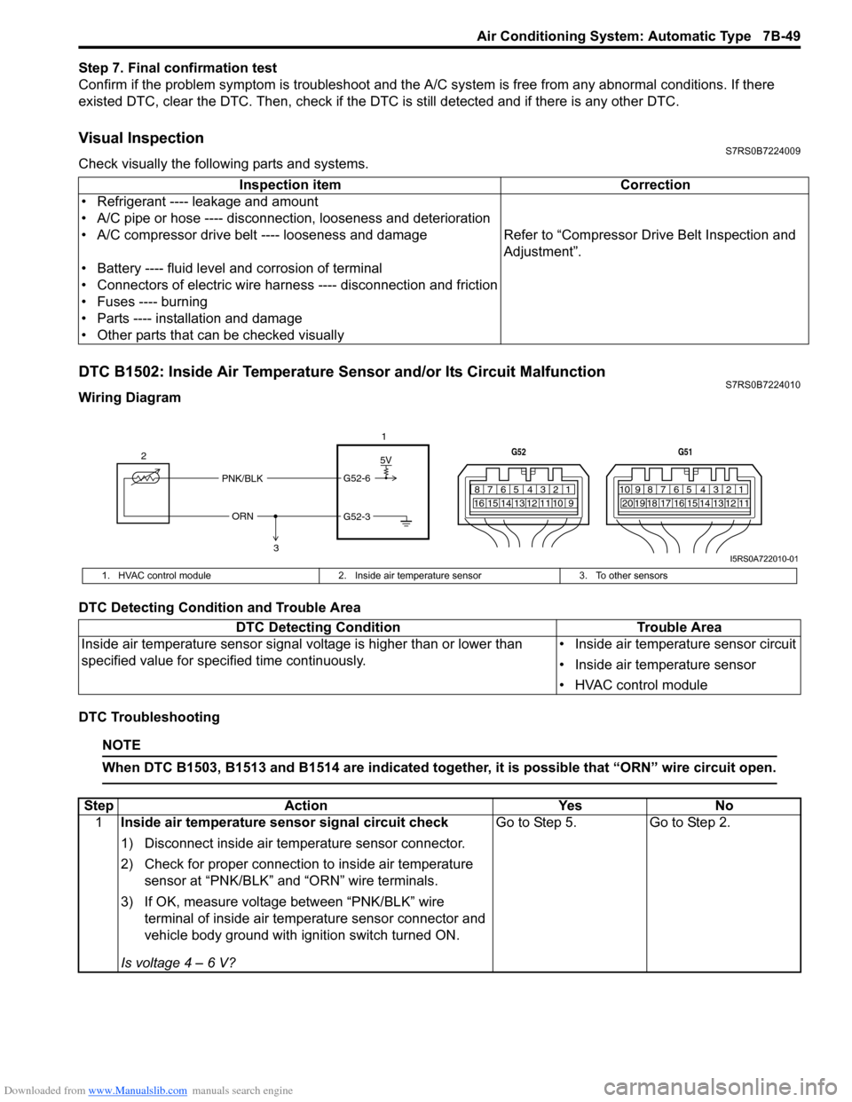
Wiring Diagram
DTC Detecting Condition and Trouble Area
DTC Troubleshooting
NOTE
When DTC B1503, B1513 and B1514 are indicated together, it is possible that “ORN” wire circuit open.
Inspection item Correction
• Refrigerant ---- leakage and amount
• A/C pipe or hose ---- disconnection, looseness and deterioration
• A/C compressor drive belt ---- looseness and damage Refer to “Compressor Drive Belt Inspection and
Adjustment”.
• Battery ---- fluid level and corrosion of terminal
• Connectors of electric wire harn ess ---- disconnection and friction
• Fuses ---- burning
• Parts ---- installation and damage
• Other parts that can be checked visually
5V
PNK/BLK
ORN G52-6
G52-3
2
1
3
7812910
65 431516 14 13 12 11
G52
789101920121112
65 431718 16 15 14 13
G51
I5RS0A722010-01
1. HVAC control module
2. Inside air temperature sensor 3. To other sensors
DTC Detecting Condition Trouble Area
Inside air temperature sensor signal voltage is higher than or lower than
specified value for specified time continuously. • Inside air temperature sensor circuit
• Inside air temperature sensor
• HVAC control module
Step
Action YesNo
1 Inside air temperature sensor signal circuit check
1) Disconnect inside air temperature sensor connector.
2) Check for proper connection to inside air temperature
sensor at “PNK/BLK” and “ORN” wire terminals.
3) If OK, measure voltage between “PNK/BLK” wire terminal of inside air temp erature sensor connector and
vehicle body ground with ignition switch turned ON.
Is voltage 4 – 6 V? Go to Step 5.
Go to Step 2.