engine mount SUZUKI SX4 2006 1.G Service Owners Manual
[x] Cancel search | Manufacturer: SUZUKI, Model Year: 2006, Model line: SX4, Model: SUZUKI SX4 2006 1.GPages: 1556, PDF Size: 37.31 MB
Page 492 of 1556
Downloaded from www.Manualslib.com manuals search engine 3A-13 Drive Shaft / Axle: Front
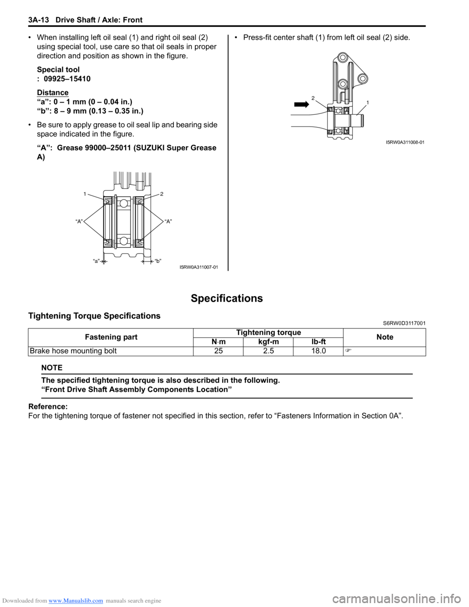
• When installing left oil seal (1) and right oil seal (2)
using special tool, use care so that oil seals in proper
direction and position as shown in the figure.
Special tool
: 09925–15410
Distance
“a”: 0 – 1 mm (0 – 0.04 in.)
“b”: 8 – 9 mm (0.13 – 0.35 in.)
• Be sure to apply grease to oil seal lip and bearing side
space indicated in the figure.
“A”: Grease 99000–25011 (SUZUKI Super Grease
A) • Press-fit center shaft (1) from left oil seal (2) side.
Specifications
Tightening Torque SpecificationsS6RW0D3117001
NOTE
The specified tightening torque is also described in the following.
“Front Drive Shaft Assembly Components Location”
Reference:
For the tightening torque of fastener not specified in this section, refer to “Fasteners Information in Section 0A”.
2 1
“A”
“b”
“a” “A”
I5RW0A311007-01
12
I5RW0A311008-01
Fastening partTightening torque
Note
N⋅mkgf-mlb-ft
Brake hose mounting bolt 25 2.5 18.0�)
Page 496 of 1556
Downloaded from www.Manualslib.com manuals search engine 3A-17 Drive Shaft / Axle: Rear
Reassembly
Refer to “Front Drive Shaft Disassembly and
Reassembly” note the following points which is different
from the front drive shaft is described.
• Apply grease to each joint.
Grease color
Wheel side: Black
Differential side: Dark gray
Amount
Wheel side: 50 – 70 g (1.8 – 2.5 oz)
Differential side: 70 – 90 g (2.5 – 3.2 oz)
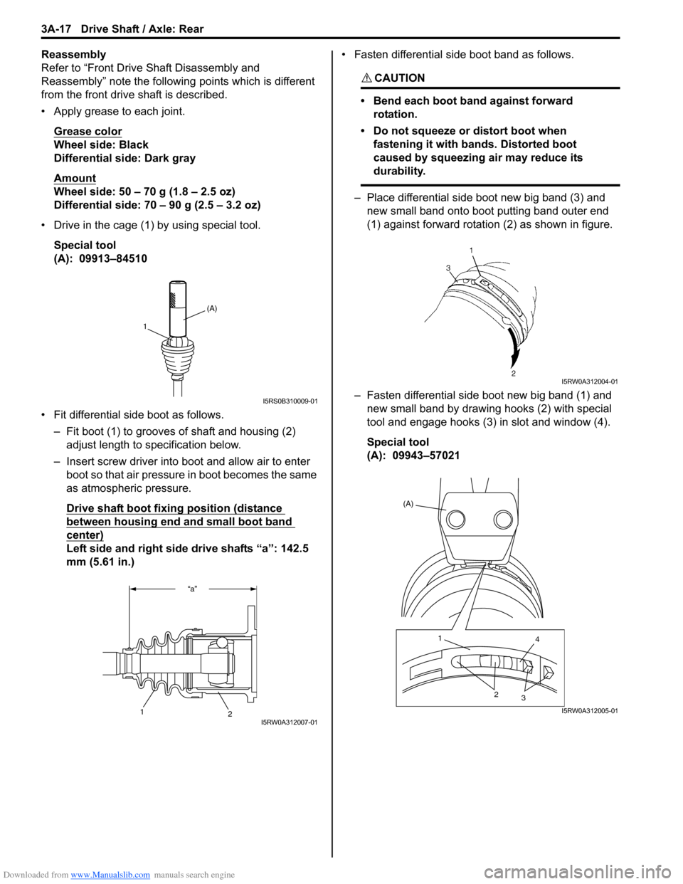
• Drive in the cage (1) by using special tool.
Special tool
(A): 09913–84510
• Fit differential side boot as follows.
– Fit boot (1) to grooves of shaft and housing (2)
adjust length to specification below.
– Insert screw driver into boot and allow air to enter
boot so that air pressure in boot becomes the same
as atmospheric pressure.
Drive shaft boot fixing position (distance
between housing end and small boot band
center)
Left side and right side drive shafts “a”: 142.5
mm (5.61 in.)• Fasten differential side boot band as follows.
CAUTION!
• Bend each boot band against forward
rotation.
• Do not squeeze or distort boot when
fastening it with bands. Distorted boot
caused by squeezing air may reduce its
durability.
– Place differential side boot new big band (3) and
new small band onto boot putting band outer end
(1) against forward rotation (2) as shown in figure.
– Fasten differential side boot new big band (1) and
new small band by drawing hooks (2) with special
tool and engage hooks (3) in slot and window (4).
Special tool
(A): 09943–57021
(A)
1
I5RS0B310009-01
“a”
2
1I5RW0A312007-01
I5RW0A312004-01
(A)
1
4
2
3
I5RW0A312005-01
Page 508 of 1556
Downloaded from www.Manualslib.com manuals search engine 3B-11 Differential:
Visual InspectionS6RW0D3204004
Check the following parts and systems visually.
DTC CheckS6RW0D3204005
1) Turn ignition switch to OFF position.
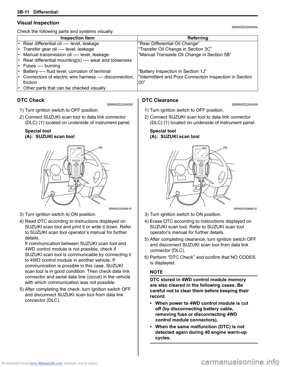
2) Connect SUZUKI scan tool to data link connector
(DLC) (1) located on underside of instrument panel.
Special tool
(A): SUZUKI scan tool
3) Turn ignition switch to ON position.
4) Read DTC according to instructions displayed on
SUZUKI scan tool and print it or write it down. Refer
to SUZUKI scan tool operator’s manual for further
details.
If communication between SUZUKI scan tool and
4WD control module is not possible, check if
SUZUKI scan tool is communicable by connecting it
to 4WD control module in another vehicle. If
communication is possible in this case, SUZUKI
scan tool is in good condition. Then check data link
connector and serial data line (circuit) in the vehicle
with which communication was not possible.
5) After completing the check, turn ignition switch OFF
and disconnect SUZUKI scan tool from data link
connector (DLC).
DTC ClearanceS6RW0D3204006
1) Turn ignition switch to OFF position.
2) Connect SUZUKI scan tool to data link connector
(DLC) (1) located on underside of instrument panel.
Special tool
(A): SUZUKI scan tool
3) Turn ignition switch to ON position.
4) Erase DTC according to instructions displayed on
SUZUKI scan tool. Refer to SUZUKI scan tool
operator’s manual for further details.
5) After completing clearance, turn ignition switch OFF
and disconnect SUZUKI scan tool from data link
connector (DLC).
6) Perform “DTC Check” and confirm that NO CODES
is displayed.
NOTE
DTC stored in 4WD control module memory
are also cleared in the following cases. Be
careful not to clear them before keeping their
record.
• When power to 4WD control module is cut
off (by disconnecting battery cable,
removing fuse or disconnecting 4WD
control module connectors).
• When the same malfunction (DTC) is not
detected again during 40 engine warm-up
cycles.
Inspection Item Referring
• Rear differential oil ---- level, leakage “Rear Differential Oil Change”
• Transfer gear oil ---- level, leakage “Transfer Oil Change in Section 3C”
• Manual transmission oil ---- level, leakage “Manual Transaxle Oil Change in Section 5B”
• Rear differential mounting(s) ---- wear and looseness
• Fuses ---- burning
• Battery ---- fluid level, corrosion of terminal “Battery Inspection in Section 1J”
• Connectors of electric wire harness ---- disconnection,
friction“Intermittent and Poor Connection Inspection in Section
00”
• Other parts that can be checked visually
1(A)I5RW0A320008-011(A)I5RW0A320008-01
Page 528 of 1556
Downloaded from www.Manualslib.com manuals search engine 3B-31 Differential:
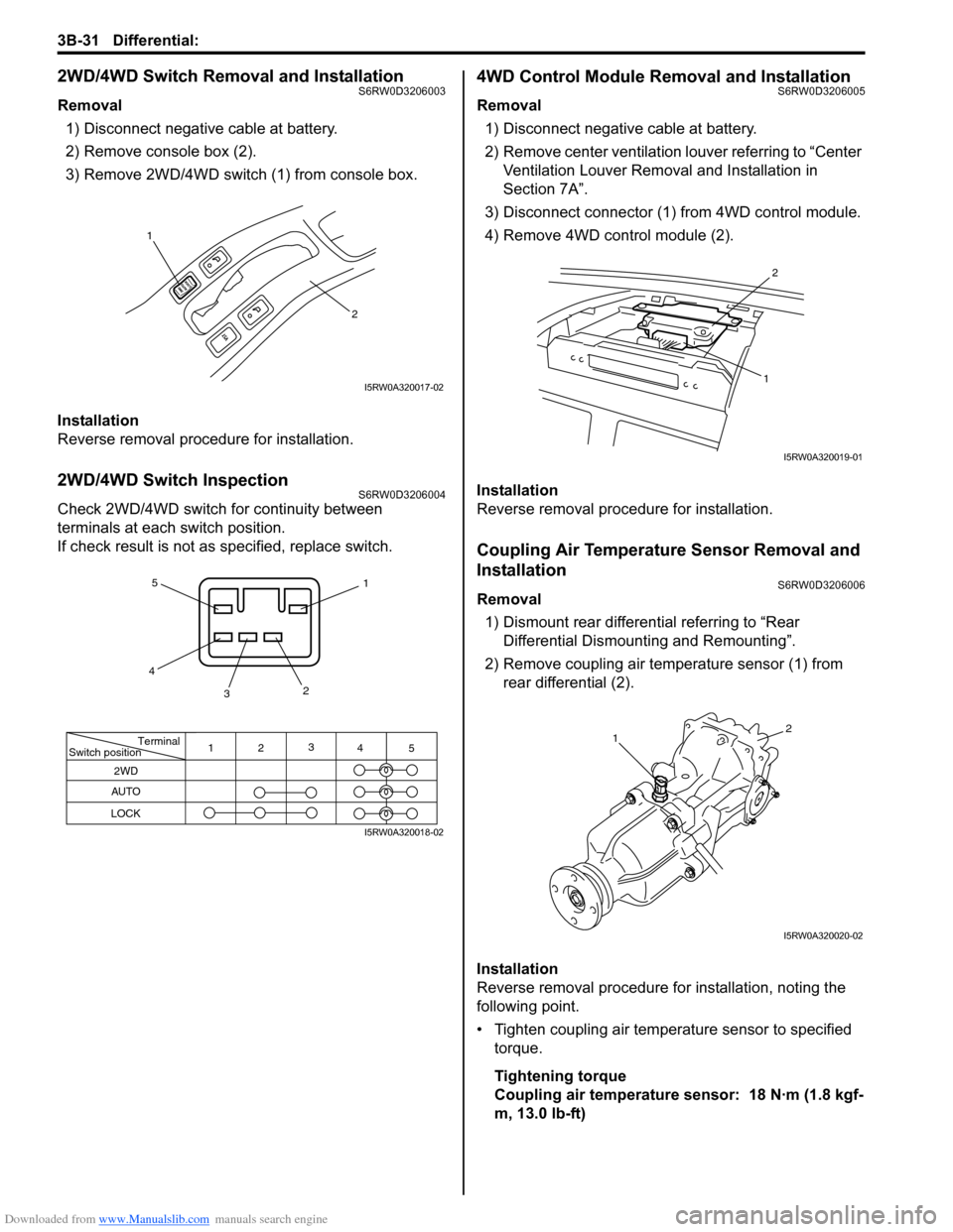
2WD/4WD Switch Removal and InstallationS6RW0D3206003
Removal
1) Disconnect negative cable at battery.
2) Remove console box (2).
3) Remove 2WD/4WD switch (1) from console box.
Installation
Reverse removal procedure for installation.
2WD/4WD Switch InspectionS6RW0D3206004
Check 2WD/4WD switch for continuity between
terminals at each switch position.
If check result is not as specified, replace switch.
4WD Control Module Removal and InstallationS6RW0D3206005
Removal
1) Disconnect negative cable at battery.
2) Remove center ventilation louver referring to “Center
Ventilation Louver Removal and Installation in
Section 7A”.
3) Disconnect connector (1) from 4WD control module.
4) Remove 4WD control module (2).
Installation
Reverse removal procedure for installation.
Coupling Air Temperature Sensor Removal and
Installation
S6RW0D3206006
Removal
1) Dismount rear differential referring to “Rear
Differential Dismounting and Remounting”.
2) Remove coupling air temperature sensor (1) from
rear differential (2).
Installation
Reverse removal procedure for installation, noting the
following point.
• Tighten coupling air temperature sensor to specified
torque.
Tightening torque
Coupling air temperature sensor: 18 N·m (1.8 kgf-
m, 13.0 lb-ft)
1
2
I5RW0A320017-02
Terminal
Switch position
2WD
AUTO
LOCK
11
22
3 3
4 4
5 5
I5RW0A320018-02
2
1
I5RW0A320019-01
12
I5RW0A320020-02
Page 530 of 1556
Downloaded from www.Manualslib.com manuals search engine 3B-33 Differential:
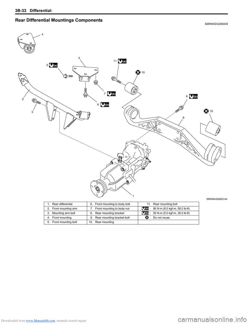
Rear Differential Mountings ComponentsS6RW0D3206009
18
10
10
3
24
54
6
(a)11
(a)
(b)9
(b) 7(b)
I5RW0A320022-04
1. Rear differential 6. Front mounting to body bolt 11. Rear mounting bolt
2. Front mounting arm 7. Front mounting to body nut : 80 N⋅m (8.0 kgf-m, 58.0 lb-ft)
3. Mounting arm bolt 8. Rear mounting bracket : 50 N⋅m (5.0 kgf-m, 36.0 lb-ft)
4. Front mounting 9. Rear mounting bracket bolt : Do not reuse.
5. Front mounting bolt 10. Rear mounting
Page 531 of 1556
Downloaded from www.Manualslib.com manuals search engine Differential: 3B-34
Front Mounting Arm and/or Rear Mounting
Bracket Assembly Removal and Installation
S6RW0D3206010
Remove and install front mounting arm and/or rear
mounting bracket after rear differential removed.
For tightening torque of each bolt and nut, refer to “Rear
Differential Mountings Components”.
Rear Mounting Bracket Assembly Disassembly
and Reassembly
S6RW0D3206011
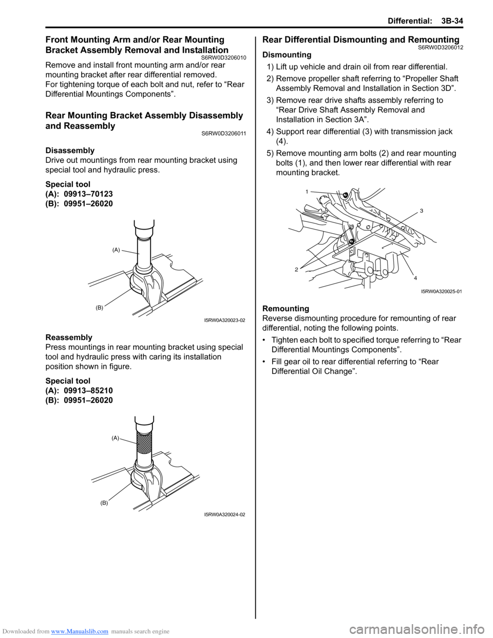
Disassembly
Drive out mountings from rear mounting bracket using
special tool and hydraulic press.
Special tool
(A): 09913–70123
(B): 09951–26020
Reassembly
Press mountings in rear mounting bracket using special
tool and hydraulic press with caring its installation
position shown in figure.
Special tool
(A): 09913–85210
(B): 09951–26020
Rear Differential Dismounting and RemountingS6RW0D3206012
Dismounting
1) Lift up vehicle and drain oil from rear differential.
2) Remove propeller shaft referring to “Propeller Shaft
Assembly Removal and Installation in Section 3D”.
3) Remove rear drive shafts assembly referring to
“Rear Drive Shaft Assembly Removal and
Installation in Section 3A”.
4) Support rear differential (3) with transmission jack
(4).
5) Remove mounting arm bolts (2) and rear mounting
bolts (1), and then lower rear differential with rear
mounting bracket.
Remounting
Reverse dismounting procedure for remounting of rear
differential, noting the following points.
• Tighten each bolt to specified torque referring to “Rear
Differential Mountings Components”.
• Fill gear oil to rear differential referring to “Rear
Differential Oil Change”.
(B)
(A)
I5RW0A320023-02
(A)
(B)
I5RW0A320024-02
3
4 21
I5RW0A320025-01
Page 533 of 1556
Downloaded from www.Manualslib.com manuals search engine Differential: 3B-36
Rear Differential Disassembly and ReassemblyS6RW0D3206014
Disassembly
1) Remove rear mounting bracket from rear differential
referring to “Front Mounting Arm and/or Rear
Mounting Bracket Assembly Removal and
Installation”.
2) Remove drive shaft flanges.
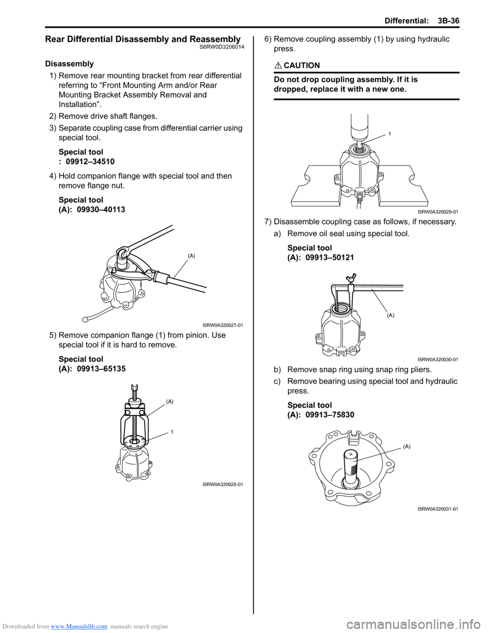
3) Separate coupling case from differential carrier using
special tool.
Special tool
: 09912–34510
4) Hold companion flange with special tool and then
remove flange nut.
Special tool
(A): 09930–40113
5) Remove companion flange (1) from pinion. Use
special tool if it is hard to remove.
Special tool
(A): 09913–651356) Remove coupling assembly (1) by using hydraulic
press.CAUTION!
Do not drop coupling assembly. If it is
dropped, replace it with a new one.
7) Disassemble coupling case as follows, if necessary.
a) Remove oil seal using special tool.
Special tool
(A): 09913–50121
b) Remove snap ring using snap ring pliers.
c) Remove bearing using special tool and hydraulic
press.
Special tool
(A): 09913–75830
(A)
I5RW0A320027-01
(A)
1
I5RW0A320028-01
1
I5RW0A320029-01
(A)
I5RW0A320030-01
(A)
I5RW0A320031-01
Page 537 of 1556
Downloaded from www.Manualslib.com manuals search engine Differential: 3B-40
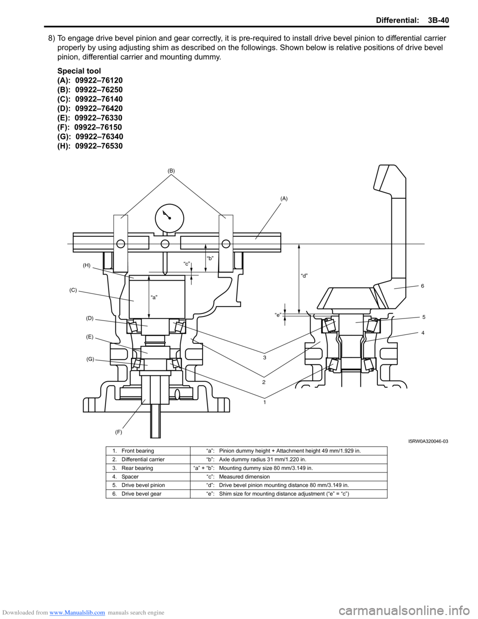
8) To engage drive bevel pinion and gear correctly, it is pre-required to install drive bevel pinion to differential carrier
properly by using adjusting shim as described on the followings. Shown below is relative positions of drive bevel
pinion, differential carrier and mounting dummy.
Special tool
(A): 09922–76120
(B): 09922–76250
(C): 09922–76140
(D): 09922–76420
(E): 09922–76330
(F): 09922–76150
(G): 09922–76340
(H): 09922–76530
3
2
14
5
6
(H)(B)
(A)
(C)
(D)
(E)
(G)
(F)
“a”“c”“b”
“d”
“e”
I5RW0A320046-03
1. Front bearing “a”: Pinion dummy height + Attachment height 49 mm/1.929 in.
2. Differential carrier “b”: Axle dummy radius 31 mm/1.220 in.
3. Rear bearing “a” + “b”: Mounting dummy size 80 mm/3.149 in.
4. Spacer “c”: Measured dimension
5. Drive bevel pinion “d”: Drive bevel pinion mounting distance 80 mm/3.149 in.
6. Drive bevel gear “e”: Shim size for mounting distance adjustment (“e” = “c”)
Page 538 of 1556

Downloaded from www.Manualslib.com manuals search engine 3B-41 Differential:
9) Set special tools and make drive bevel pinion
mounting dummy.
Special tool
(A): 09922–76120
(B): 09922–76250
10) Install dial gauge (1) to mounting dummy as shown
in figure.
Special tool set distance
“a”: 38.0 mm (1.496 in.)
“b”: 0 mm (0.000 in.)
11) Set special tools and make drive bevel pinion
dummy.
Special tool
(A): 09922–76140
(B): 09922–76420
(C): 09922–76330
(D): 09922–7634012) Apply gear oil to drive bevel pinion bearings, install
special tools with bearings to differential carrier as
shown in figure.
Special tool
(A): 09922–76140
(B): 09922–76420
(C): 09922–76330
(D): 09922–76340
(E): 09922–76150
(F): 09922–76530
NOTE
This installation requires no spacer or oil
seal.
13) Tighten bevel pinion nut (special tool) (1) so that
specified bearing preload is obtained.
NOTE
Before taking measurement, check for
rotation by hand more than 15 revolutions.
Pinion bearing preload (at 50 r/min)
: 1.3 – 2.6 N⋅m (13.0 – 26.0 kgf-cm, 11.3 – 22.6 lb-
in.)
I5RW0A320047-01
(C)
(D)
(A)
(A)(B)I5RW0A320048-01
(E) (D) (C)(B) (A) (F)I5RW0A320049-01
1
I5RW0A320050-01
Page 539 of 1556
Downloaded from www.Manualslib.com manuals search engine Differential: 3B-42
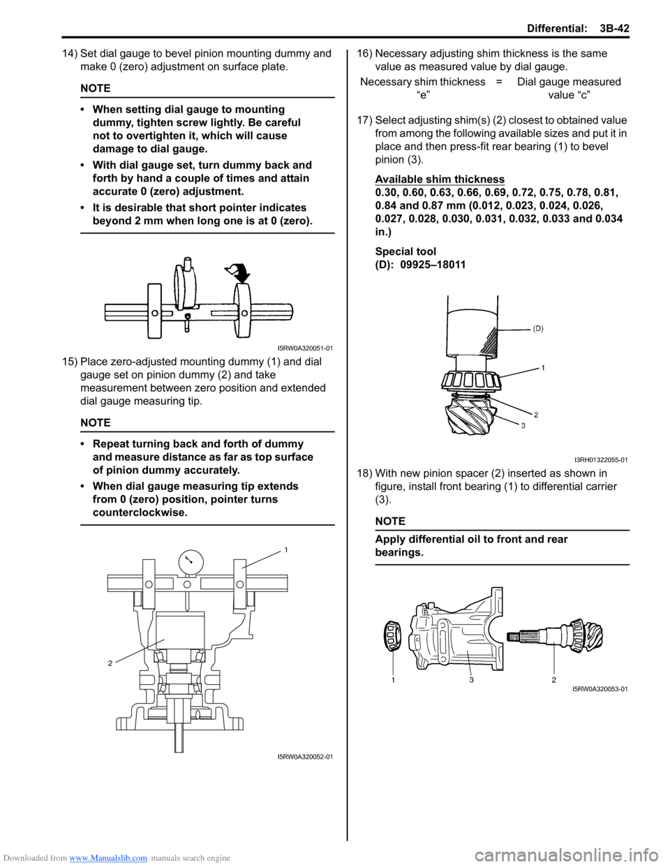
14) Set dial gauge to bevel pinion mounting dummy and
make 0 (zero) adjustment on surface plate.
NOTE
• When setting dial gauge to mounting
dummy, tighten screw lightly. Be careful
not to overtighten it, which will cause
damage to dial gauge.
• With dial gauge set, turn dummy back and
forth by hand a couple of times and attain
accurate 0 (zero) adjustment.
• It is desirable that short pointer indicates
beyond 2 mm when long one is at 0 (zero).
15) Place zero-adjusted mounting dummy (1) and dial
gauge set on pinion dummy (2) and take
measurement between zero position and extended
dial gauge measuring tip.
NOTE
• Repeat turning back and forth of dummy
and measure distance as far as top surface
of pinion dummy accurately.
• When dial gauge measuring tip extends
from 0 (zero) position, pointer turns
counterclockwise.
16) Necessary adjusting shim thickness is the same
value as measured value by dial gauge.
17) Select adjusting shim(s) (2) closest to obtained value
from among the following available sizes and put it in
place and then press-fit rear bearing (1) to bevel
pinion (3).
Available shim thickness
0.30, 0.60, 0.63, 0.66, 0.69, 0.72, 0.75, 0.78, 0.81,
0.84 and 0.87 mm (0.012, 0.023, 0.024, 0.026,
0.027, 0.028, 0.030, 0.031, 0.032, 0.033 and 0.034
in.)
Special tool
(D): 09925–18011
18) With new pinion spacer (2) inserted as shown in
figure, install front bearing (1) to differential carrier
(3).
NOTE
Apply differential oil to front and rear
bearings.
I5RW0A320051-01
1
2
I5RW0A320052-01
Necessary shim thickness
“e”= Dial gauge measured
value “c”
I3RH01322055-01
I5RW0A320053-01