SUZUKI SX4 2006 1.G Service Workshop Manual
Manufacturer: SUZUKI, Model Year: 2006, Model line: SX4, Model: SUZUKI SX4 2006 1.GPages: 1556, PDF Size: 37.31 MB
Page 941 of 1556
Downloaded from www.Manualslib.com manuals search engine Air Conditioning System: Manual Type 7B-1
HVAC
Air Conditioning System
Manual Type
Precautions
A/C System CautionS6RW0D7210001
CAUTION!
The A/C system of this vehicle uses HFC-134a (R-134a) refrigerant, specified compressor oil and
specified parts.
Do not use CFC-12 (R-12) refrigerant, R-12 exclusive use compressor oil and R-12 exclusive parts in
this A/C system, do not attempt to use R-12 servicing equipment. Otherwise, use of it will result in
leakage of refrigerant, damage or other faulty condition of A/C system and damage or other faulty
condition of servicing equipment.
When replenishing or changing refrigerant and compressor oil and when replacing parts, make sure
that the material or the part to be used is appropriate to the A/C installed in the vehicle being serviced.
Use of incorrect one will result in leakage of refrigerant, damage in parts or other faulty condition.
Precautions on Servicing A/C SystemS6RW0D7210002
WARNING!
Should refrigerant HFC-134a (R-134a) is exposed to your eye(s), consult a doctor immediately.
• Do not reuse your hand to rub affected eye(s). Instead, use fresh cold water to splash it over
affected area to thus gradually raise its temperature above the freezing point.
• Obtain proper treatment as soon as possible from a doctor or eye specialist. Should liquid
refrigerant HFC-134a (R-134a) is exposed to your skin, such affected part should be treated in the
same manner as when skin is frostbitten or frozen.
Handling Refrigerant HFC-134a (R-134a)
• Always wear goggles to protect your eyes.
• Avoid direct contact to liquid refrigerant.
• Do not heat refrigerant container higher than 40 °C (104 °F).
• Do not discharge refrigerant into atmosphere.
• Do not expose bright metals to liquid refrigerant. Refrigerant combined with moisture is corrosive and tarnishes
surfaces of bright metals including chrome.
• Never use heat for bending pipes. When bending a pipe, try to make its bending angle as smooth as possible.
• Keep internal parts of air conditioning free from moisture and dirt. When disconnecting any line from system, install
a blind plug or cap to the fitting immediately.
• When handling recovery and recycling equipment, be sure to follow the instruction manual for the equipment.
• Check local governmental regulations regarding working with refrigerator systems and its tooling.
• When connecting hoses and pipes, apply a few drops of compressor oil (refrigerant oil) to O-ring.
• Replace O-ring with new one once hoses, pipes and parts disconnected.
• When tightening or loosening a fitting, use two wrenches, one for turning and the other for support.
• Route drain hose so that drained water does not make any contact to vehicle components.
• If pipes or hoses are replaced, replenish specified amount of compressor oil to compressor suction side referring to
“Replenishing Compressor Oil” in “Operation Procedure for Refrigerant Charge”.
Page 942 of 1556

Downloaded from www.Manualslib.com manuals search engine 7B-2 Air Conditioning System: Manual Type
Refrigerant Recovery
When discharging refrigerant out of A/C system, always recover it by using refrigerant recovery and recycling
equipment because discharging refrigerant HFC-134a (R-134a) into atmosphere would cause adverse effect to
environments referring to “Recovery” in “Operation Procedure for Refrigerant Charge”.
Refrigerant Charge
After performing compressor oil replenishment and evacuation, charge a proper amount of refrigerant to A/C system
referring to “Charge” in “Operation Procedure for Refrigerant Charge”.
General Description
Sub-Cool A/C System DescriptionS6RW0D7211001
In the sub-cool A/C system (condenser integrated with receiver / dryer), the inside of the condenser is divided into the
condensation part and the sub-cooler part, and the receiver / dryer is located between those. In the receiver / dryer,
the refrigerant is separated into the vapor refrigerant and the liquid refrigerant. Only the liquid refrigerant is delivered to
the sub-cooler part of the condenser. The refrigerant is supercooled by the sub-cooler part of the condenser.
I5RW0A721003-02
[A]: Liquid 2. Magnet clutch 6. Expansion valve 10. Desiccant
[B]: Vapor 3. Condenser 7. A/C evaporator 11. Filter
[C]: Superheated vapor 4. Receiver/dryer 8. Condensation part 12. Vapor refrigerant
1. Compressor 5. Refrigerant pressure sensor 9. Sub-cooler part 13. Liquid refrigerant
Page 943 of 1556
Downloaded from www.Manualslib.com manuals search engine Air Conditioning System: Manual Type 7B-3
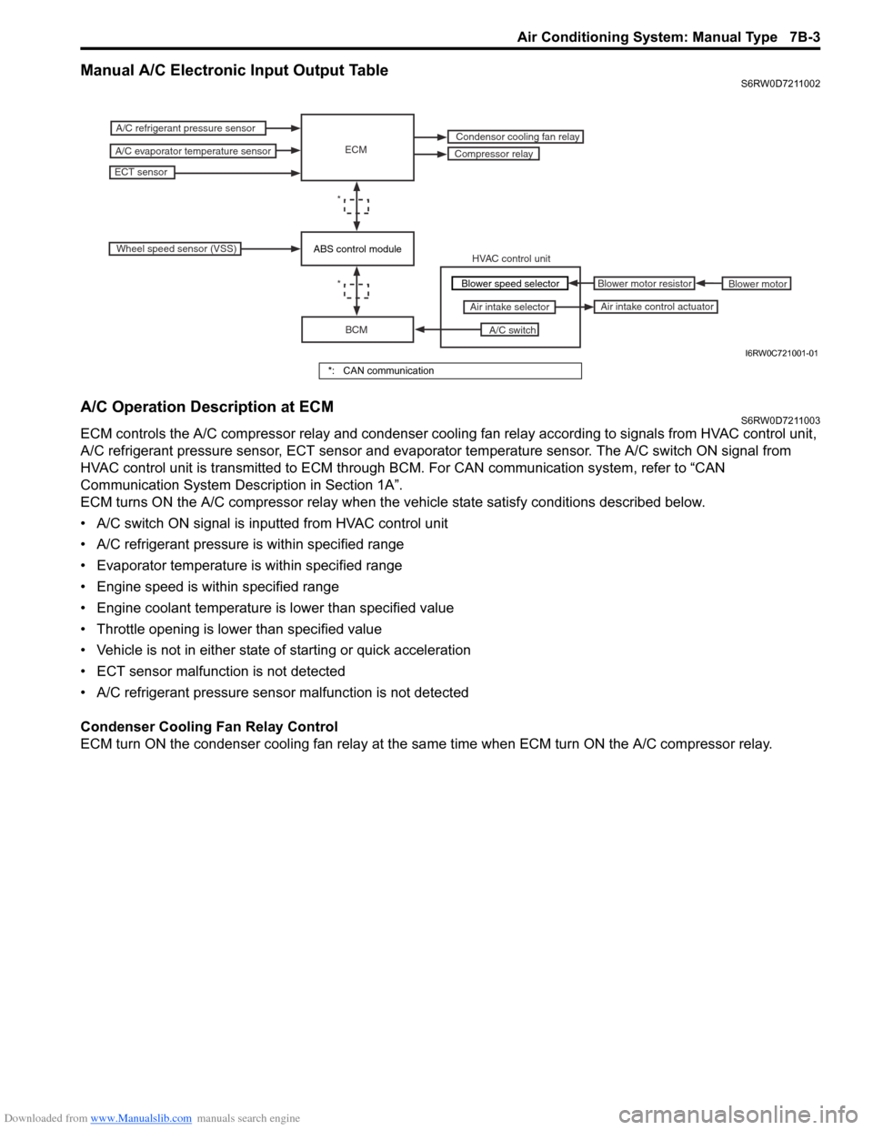
Manual A/C Electronic Input Output TableS6RW0D7211002
A/C Operation Description at ECMS6RW0D7211003
ECM controls the A/C compressor relay and condenser cooling fan relay according to signals from HVAC control unit,
A/C refrigerant pressure sensor, ECT sensor and evaporator temperature sensor. The A/C switch ON signal from
HVAC control unit is transmitted to ECM through BCM. For CAN communication system, refer to “CAN
Communication System Description in Section 1A”.
ECM turns ON the A/C compressor relay when the vehicle state satisfy conditions described below.
• A/C switch ON signal is inputted from HVAC control unit
• A/C refrigerant pressure is within specified range
• Evaporator temperature is within specified range
• Engine speed is within specified range
• Engine coolant temperature is lower than specified value
• Throttle opening is lower than specified value
• Vehicle is not in either state of starting or quick acceleration
• ECT sensor malfunction is not detected
• A/C refrigerant pressure sensor malfunction is not detected
Condenser Cooling Fan Relay Control
ECM turn ON the condenser cooling fan relay at the same time when ECM turn ON the A/C compressor relay.
ECM
BCM
A/C switch Air intake selector
A/C refrigerant pressure sensor
A/C evaporator temperature sensorCompressor relay
ECT sensor
Condensor cooling fan relay
*
Wheel speed sensor (VSS)
HVAC control unit
Blower motor Blower motor resistor
Air intake control actuator
*Blower speed selector
ABS control module
I6RW0C721001-01
*: CAN communication
Page 944 of 1556
Downloaded from www.Manualslib.com manuals search engine 7B-4 Air Conditioning System: Manual Type
Schematic and Routing Diagram
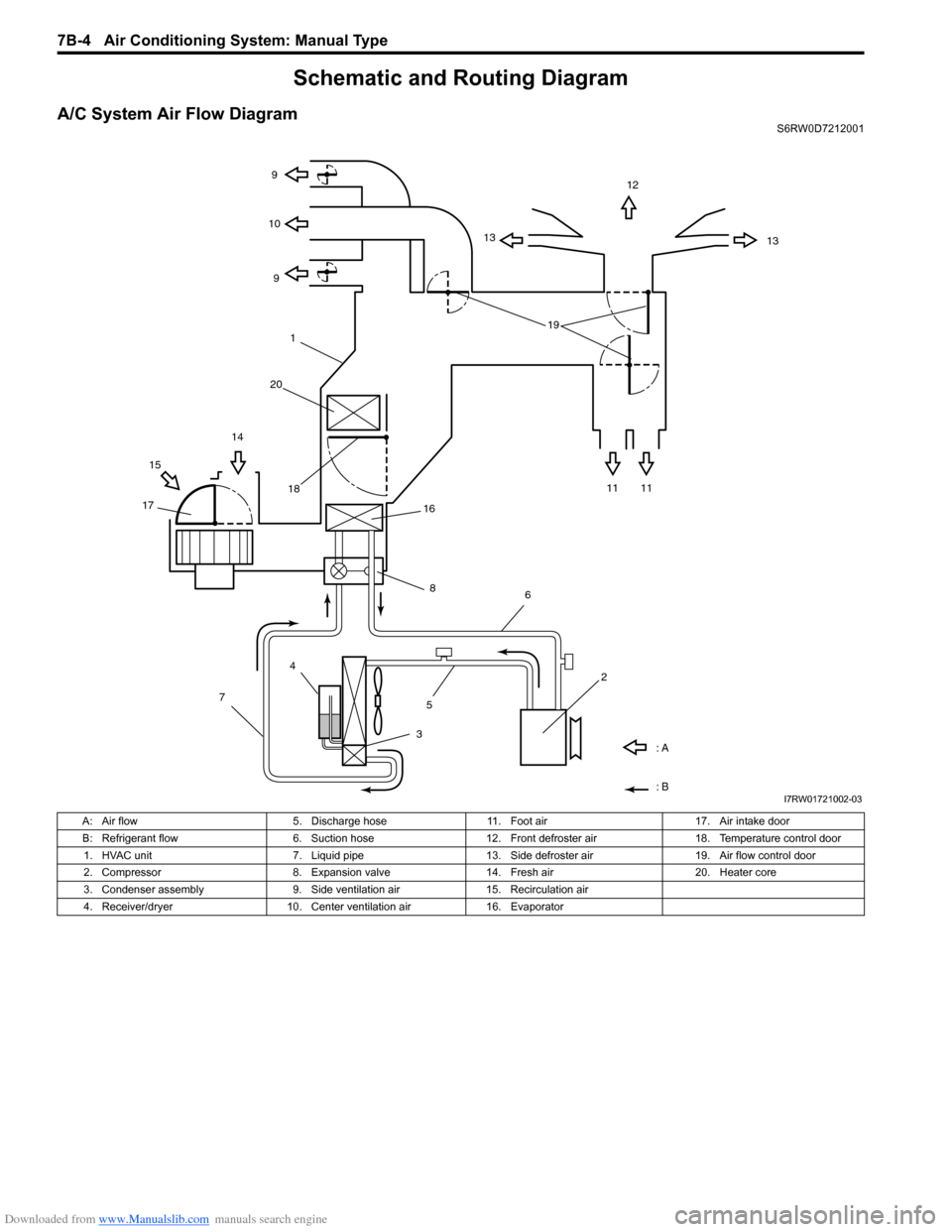
A/C System Air Flow DiagramS6RW0D7212001
1312
13 9
9 10
11 11 1514
1718
: A
: B
4
7
356
2 16
8
191
20
I7RW01721002-03
A: Air flow 5. Discharge hose 11. Foot air 17. Air intake door
B: Refrigerant flow 6. Suction hose 12. Front defroster air 18. Temperature control door
1. HVAC unit 7. Liquid pipe 13. Side defroster air 19. Air flow control door
2. Compressor 8. Expansion valve 14. Fresh air 20. Heater core
3. Condenser assembly 9. Side ventilation air 15. Recirculation air
4. Receiver/dryer 10. Center ventilation air 16. Evaporator
Page 945 of 1556
![SUZUKI SX4 2006 1.G Service Workshop Manual Downloaded from www.Manualslib.com manuals search engine Air Conditioning System: Manual Type 7B-5
A/C System Wiring DiagramS6RW0D7212002
[A]
7
WHT
GRN5YELBLK
3
G154-3
G154-4
G154-7
G154-8
G154-10
G15 SUZUKI SX4 2006 1.G Service Workshop Manual Downloaded from www.Manualslib.com manuals search engine Air Conditioning System: Manual Type 7B-5
A/C System Wiring DiagramS6RW0D7212002
[A]
7
WHT
GRN5YELBLK
3
G154-3
G154-4
G154-7
G154-8
G154-10
G15](/img/20/7612/w960_7612-944.png)
Downloaded from www.Manualslib.com manuals search engine Air Conditioning System: Manual Type 7B-5
A/C System Wiring DiagramS6RW0D7212002
[A]
7
WHT
GRN5YELBLK
3
G154-3
G154-4
G154-7
G154-8
G154-10
G154-13
G154-5
G154-6
G155-5
G155-2
G155-3
G155-7
G155-6
G155-1
G154-9
G154-14
BLK/WHT
YEL
BLU/WHT
RED
BRN
GRN/WHT
RED/BLK
RED
GRN
GRN/YEL
RED/YEL
RED/BLU
20
21
23 22
BLK/RED
6 2
MBLK/WHTBLK/YEL
M
11
4RED/YEL 1
E01-49
12
E01-16
GRY 13
12V
BLU/WHTE01-3510
E01-48
18
19RED/BLK
BLK/RED
BLK/RED
BRN/WHTE01-60
E01-1
E01-29BLK/WHT
M
BLU/YELBLK/YEL
5V5V 5V
WHT/BLK
9
ORN
14E01-36
C01-12C01-14GRY/REDRED/BLU
E01-41
RED/BLK
RED
WHT
8
BLK
BLK/ORN
BLU IG1
IG2
5V
17
28
29
31
2726 2524
16
16
30
34
33E01-4 E01-19WHTRED
C01-50C01-49WHTRED
32
LT GRN
C01-57
C01-2415
GRY/BLU5V
I6RW0C721002-01
[A]: Illumination control model 9. A/C refrigerant pressure
sensor18. Condenser cooling fan relay 27. Illumination light
1. Ignition switch 10. ECM 19. Condenser cooling fan motor 28. Rear defogger relay
2. Blower motor 11. Air intake control actuator 20. Blower speed selector 29. Rear defogger
3. HVAC control unit 12. Compressor relay 21. A/C switch 30. Main relay
4. Lighting switch 13. Compressor 22. Air intake selector 31. Tail light
5. Blower motor relay 14. Evaporator temperature
sensor23. Rear defogger switch 32. TCM
6. Blower motor resistor 15. ECT sensor 24. “A/C” indicator light 33. To other control module and DLC
7. Junction block assembly 16. To BCM 25. “REC” indicator light 34. ABS control module
8. BCM 17. Main fuse box 26. Rear defogger indicator
Page 946 of 1556
Downloaded from www.Manualslib.com manuals search engine 7B-6 Air Conditioning System: Manual Type
Component Location
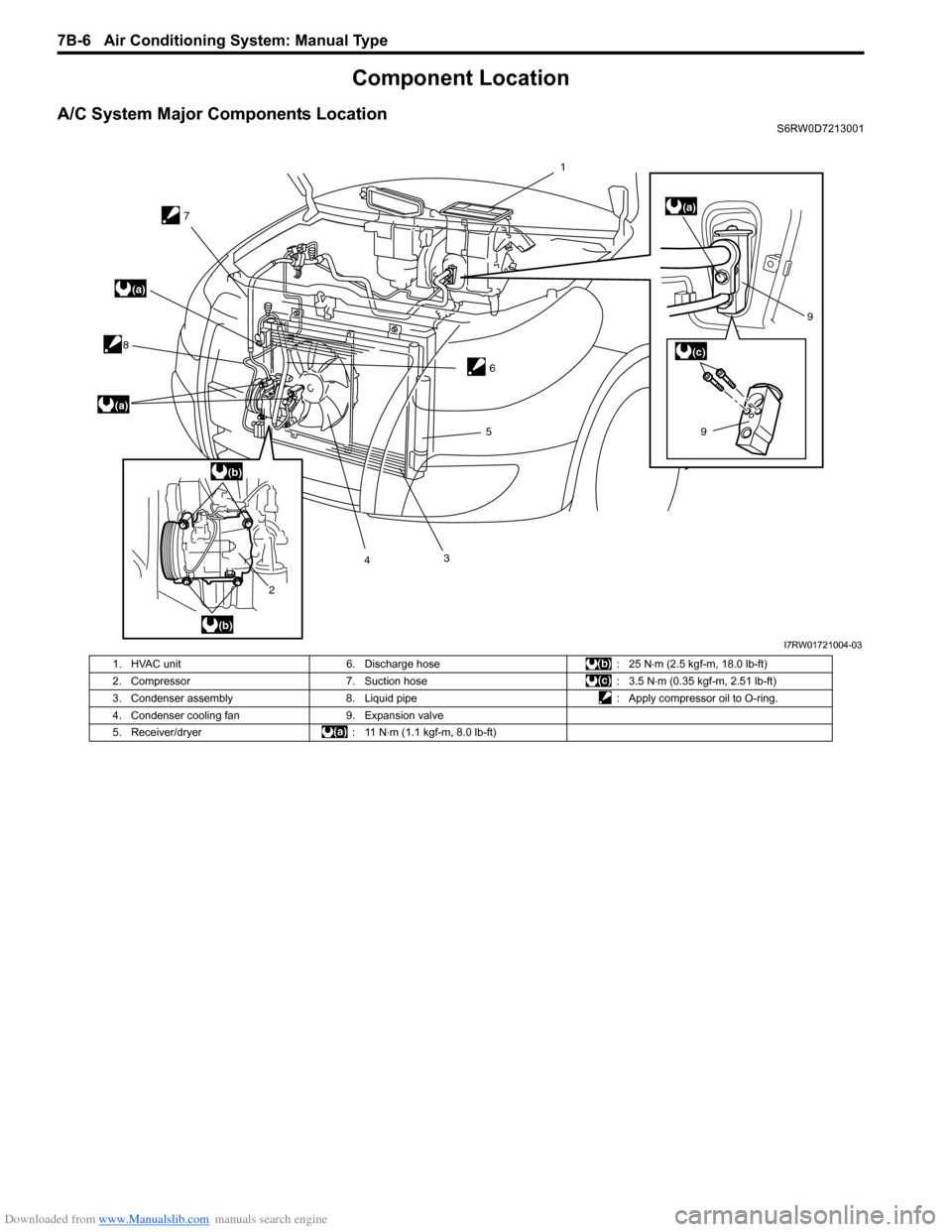
A/C System Major Components LocationS6RW0D7213001
7
8
2435
69
9
(a)
(a)
(a)
(b)
(b)
(c)
1
I7RW01721004-03
1. HVAC unit 6. Discharge hose : 25 N⋅m (2.5 kgf-m, 18.0 lb-ft)
2. Compressor 7. Suction hose : 3.5 N⋅m (0.35 kgf-m, 2.51 lb-ft)
3. Condenser assembly 8. Liquid pipe : Apply compressor oil to O-ring.
4. Condenser cooling fan 9. Expansion valve
5. Receiver/dryer : 11 N⋅m (1.1 kgf-m, 8.0 lb-ft)
Page 947 of 1556
Downloaded from www.Manualslib.com manuals search engine Air Conditioning System: Manual Type 7B-7
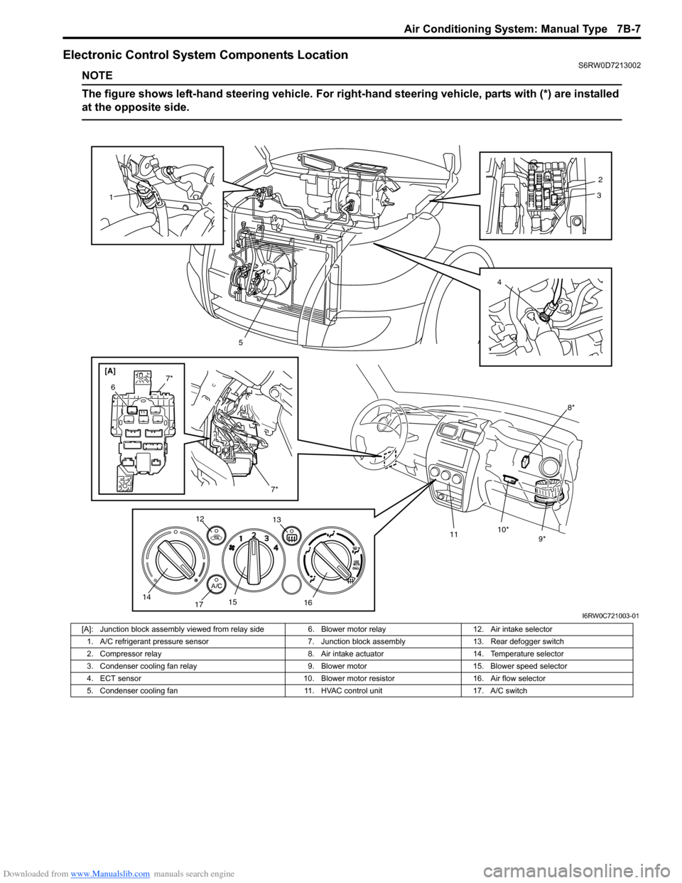
Electronic Control System Components LocationS6RW0D7213002
NOTE
The figure shows left-hand steering vehicle. For right-hand steering vehicle, parts with (*) are installed
at the opposite side.
[A]
8*
9* 10*
11
1
5
7*
6
7*
12
13
14
1715
1642
3
I6RW0C721003-01
[A]: Junction block assembly viewed from relay side 6. Blower motor relay 12. Air intake selector
1. A/C refrigerant pressure sensor 7. Junction block assembly 13. Rear defogger switch
2. Compressor relay 8. Air intake actuator 14. Temperature selector
3. Condenser cooling fan relay 9. Blower motor 15. Blower speed selector
4. ECT sensor 10. Blower motor resistor 16. Air flow selector
5. Condenser cooling fan 11. HVAC control unit 17. A/C switch
Page 948 of 1556
Downloaded from www.Manualslib.com manuals search engine 7B-8 Air Conditioning System: Manual Type
Diagnostic Information and Procedures
A/C System Performance InspectionS6RW0D7214001
1) Confirm that vehicle and environmental conditions
are as follows.
• Vehicle is put indoors.
• Ambient temperature is within 25 – 35 °C (77 – 95
°F).
• Relative humidity is within 30 – 70%.
• There is no wind indoors.
• HVAC unit is normal.
• Blower motor is normal.
• There is no air leakage from air ducts.
• Condenser fins are clean.
• HVAC air filter is not clogged with dirt and dust (if
equipped).
• Battery voltage is about 12 V.
• Radiator cooling fan operates normally.
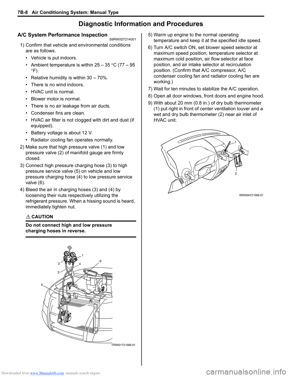
2) Make sure that high pressure valve (1) and low
pressure valve (2) of manifold gauge are firmly
closed.
3) Connect high pressure charging hose (3) to high
pressure service valve (5) on vehicle and low
pressure charging hose (4) to low pressure service
valve (6).
4) Bleed the air in charging hoses (3) and (4) by
loosening their nuts respectively utilizing the
refrigerant pressure. When a hissing sound is heard,
immediately tighten nut.
CAUTION!
Do not connect high and low pressure
charging hoses in reverse.
5) Warm up engine to the normal operating
temperature and keep it at the specified idle speed.
6) Turn A/C switch ON, set blower speed selector at
maximum speed position, temperature selector at
maximum cold position, air flow selector at face
position, and air intake selector at recirculation
position. (Confirm that A/C compressor, A/C
condenser cooling fan and radiator cooling fan are
working.)
7) Wait for ten minutes to stabilize the A/C operation.
8) Open all door windows, front doors and engine hood.
9) With about 20 mm (0.8 in.) of dry bulb thermometer
(1) put right in front of center ventilation louver and a
wet and dry bulb thermometer (2) near air inlet of
HVAC unit.
321
4
6
5
I7RW01721006-01
2
1
I5RW0A721008-01
Page 949 of 1556
Downloaded from www.Manualslib.com manuals search engine Air Conditioning System: Manual Type 7B-9
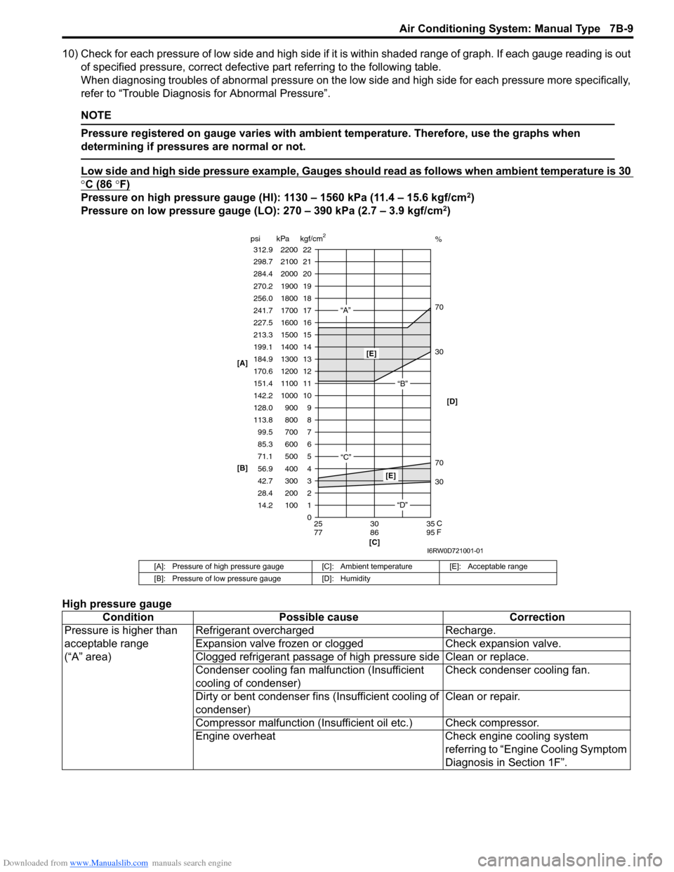
10) Check for each pressure of low side and high side if it is within shaded range of graph. If each gauge reading is out
of specified pressure, correct defective part referring to the following table.
When diagnosing troubles of abnormal pressure on the low side and high side for each pressure more specifically,
refer to “Trouble Diagnosis for Abnormal Pressure”.
NOTE
Pressure registered on gauge varies with ambient temperature. Therefore, use the graphs when
determining if pressures are normal or not.
Low side and high side pressure example, Gauges should read as follows when ambient temperature is 30
°C (86 °F)
Pressure on high pressure gauge (HI): 1130 – 1560 kPa (11.4 – 15.6 kgf/cm2)
Pressure on low pressure gauge (LO): 270 – 390 kPa (2.7 – 3.9 kgf/cm2)
High pressure gauge
[A]: Pressure of high pressure gauge [C]: Ambient temperature [E]: Acceptable range
[B]: Pressure of low pressure gauge [D]: Humidity
Condition Possible cause Correction
Pressure is higher than
acceptable range
(“A” area)Refrigerant overcharged Recharge.
Expansion valve frozen or clogged Check expansion valve.
Clogged refrigerant passage of high pressure side Clean or replace.
Condenser cooling fan malfunction (Insufficient
cooling of condenser)Check condenser cooling fan.
Dirty or bent condenser fins (Insufficient cooling of
condenser)Clean or repair.
Compressor malfunction (Insufficient oil etc.) Check compressor.
Engine overheat Check engine cooling system
referring to “Engine Cooling Symptom
Diagnosis in Section 1F”.
22 312.9 2200
0 1 2 3
30 70 30 70%
4 5 6 7 8 9 10
11 12 13
14
15
16
17
18
19 21 298.7 2100
20
14.2 28.4 42.7 56.9 71.1 85.3 99.5 113.8 128.0
142.2
151.4 170.6 184.9
199.1
213.3
227.5
241.7
256.0
270.2
284.4
100 200 300 400 500 600 700 800 900 1000
1100 1200 1300
1400
1500
1600
1700
1800
1900
2000
25 30 35
77 86 95 psi kPa kgf/cm
2
[C] [B] [A]
C
F
“A”
“B”
“C”
[E]
[E]
“D”[D]
I6RW0D721001-01
Page 950 of 1556
Downloaded from www.Manualslib.com manuals search engine 7B-10 Air Conditioning System: Manual Type
Low pressure gauge
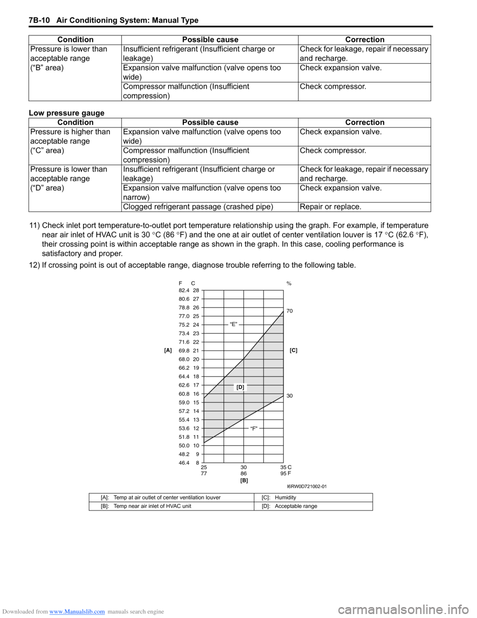
11) Check inlet port temperature-to-outlet port temperature relationship using the graph. For example, if temperature
near air inlet of HVAC unit is 30 °C (86 °F) and the one at air outlet of center ventilation louver is 17 °C (62.6 °F),
their crossing point is within acceptable range as shown in the graph. In this case, cooling performance is
satisfactory and proper.
12) If crossing point is out of acceptable range, diagnose trouble referring to the following table. Pressure is lower than
acceptable range
(“B” area)Insufficient refrigerant (Insufficient charge or
leakage)Check for leakage, repair if necessary
and recharge.
Expansion valve malfunction (valve opens too
wide)Check expansion valve.
Compressor malfunction (Insufficient
compression)Check compressor.
Condition Possible cause Correction
Pressure is higher than
acceptable range
(“C” area)Expansion valve malfunction (valve opens too
wide)Check expansion valve.
Compressor malfunction (Insufficient
compression)Check compressor.
Pressure is lower than
acceptable range
(“D” area)Insufficient refrigerant (Insufficient charge or
leakage)Check for leakage, repair if necessary
and recharge.
Expansion valve malfunction (valve opens too
narrow)Check expansion valve.
Clogged refrigerant passage (crashed pipe) Repair or replace.
[A]: Temp at air outlet of center ventilation louver [C]: Humidity
[B]: Temp near air inlet of HVAC unit [D]: Acceptable range
Condition Possible cause Correction
8 9 10 11 12 13
14 15 16
17 18 19
20 21
22 23
24
25
26
27
28
46.4 48.2 50.0 51.8 53.6 55.4
57.2 59.0 60.8
62.6 64.4 66.2
68.0 69.8
71.6 73.4
75.2
77.0
78.8
80.6
82.4
25 30 35
77 86 95 F C
C
F
“E”
“F”
[D]
[B]
30 70 %
[C] [A]
I6RW0D721002-01