TOYOTA AVENSIS 2005 Service Repair Manual
Manufacturer: TOYOTA, Model Year: 2005, Model line: AVENSIS, Model: TOYOTA AVENSIS 2005Pages: 5135, PDF Size: 95.28 MB
Page 1491 of 5135
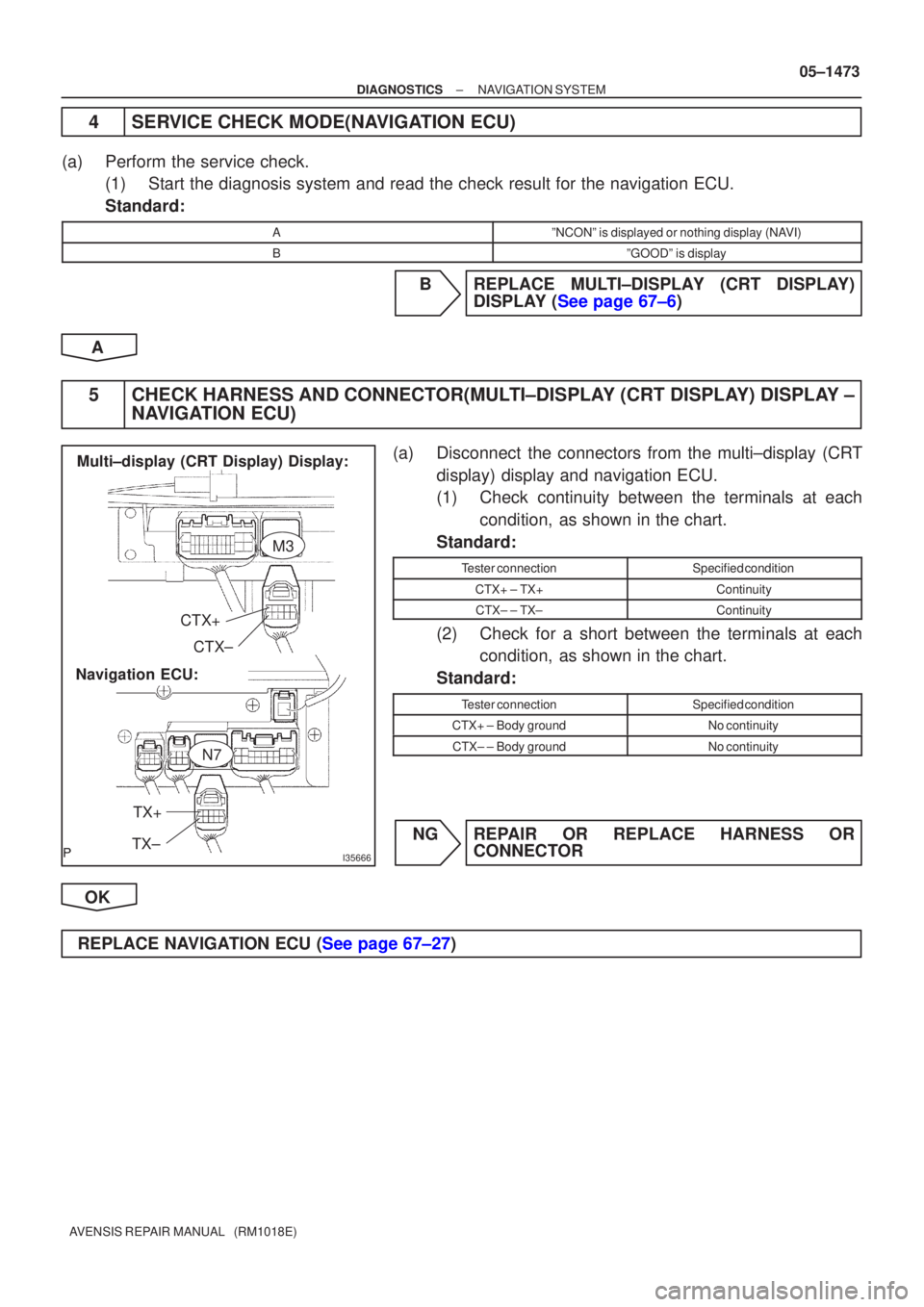
I35666
CTX+CTX±
TX+
TX±
Navigation ECU: Multi±display (CRT Display) Display:
M3
N7
±
DIAGNOSTICS NAVIGATION SYSTEM
05±1473
AVENSIS REPAIR MANUAL (RM1018E)
4SERVICE CHECK MODE(NAVIGATION ECU)
(a)Perform the service check.
(1)Start the diagnosis system and read the check result for the navigation \
ECU.
Standard:
AºNCONº is displayed or nothing display (NAVI)
BºGOODº is display
BREPLACE MULTI±DISPLAY (CRT DISPLAY) DISPLAY (See page 67±6)
A
5CHECK HARNESS AND CONNECTOR(MULTI±DISPLAY (CRT DISPLAY) DISPLAY ± NAVIGATION ECU)
(a)Disconnect the connectors from the multi±display (CRT
display) display and navigation ECU.
(1)Check continuity between the terminals at eachcondition, as shown in the chart.
Standard:
Tester connectionSpecified condition
CTX+ ± TX+Continuity
CTX± ± TX±Continuity
(2)Check for a short between the terminals at each condition, as shown in the chart.
Standard:
Tester connectionSpecified condition
CTX+ ± Body groundNo continuity
CTX± ± Body groundNo continuity
NGREPAIR OR REPLACE HARNESS OR CONNECTOR
OK
REPLACE NAVIGATION ECU (See page 67±27)
Page 1492 of 5135
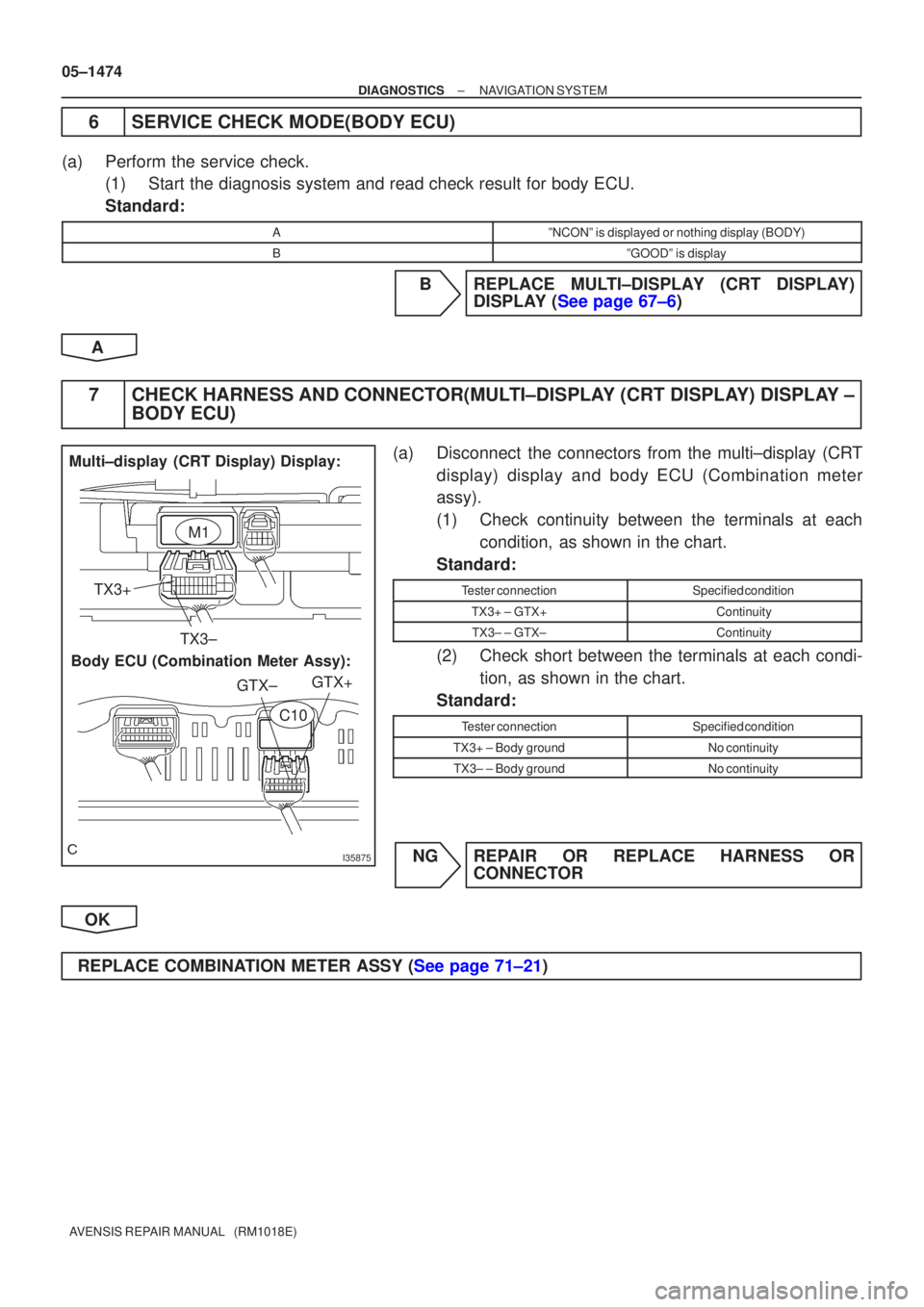
I35875
Multi±display (CRT Display) Display:Body ECU (Combination Meter Assy): TX3+
TX3± GTX+
GTX±
M1
C10
05±1474
±
DIAGNOSTICS NAVIGATION SYSTEM
AVENSIS REPAIR MANUAL (RM1018E)
6SERVICE CHECK MODE(BODY ECU)
(a)Perform the service check. (1)Start the diagnosis system and read check result for body ECU.
Standard:
AºNCONº is displayed or nothing display (BODY)
BºGOODº is display
BREPLACE MULTI±DISPLAY (CRT DISPLAY) DISPLAY (See page 67±6)
A
7CHECK HARNESS AND CONNECTOR(MULTI±DISPLAY (CRT DISPLAY) DISPLAY ± BODY ECU)
(a)Disconnect the connectors from the multi±display (CRT
display) display and body ECU (Combination meter
assy).
(1)Check continuity between the terminals at eachcondition, as shown in the chart.
Standard:
Tester connectionSpecified condition
TX3+ ± GTX+Continuity
TX3± ± GTX±Continuity
(2)Check short between the terminals at each condi- tion, as shown in the chart.
Standard:
Tester connectionSpecified condition
TX3+ ± Body groundNo continuity
TX3± ± Body groundNo continuity
NGREPAIR OR REPLACE HARNESS OR CONNECTOR
OK
REPLACE COMBINATION METER ASSY (See page 71±21)
Page 1493 of 5135
I34728
I13
Ignition SW
32
AM1 ACC
G±R34
11 DH
DH DNDB RAD No.1
AM1 GDriver Side J/BFF
(*3) (*4)J8 J20
FF
(*3) (*4)J8 J20J/CACC
B±G (*1)
B±G (*1)
B (*2) B±G (*1)
FL MAIN
Battery
*1: Gasoline
*2: 1CD±FTV
*3: LHD
*4: RHD1
4BALT
121
4D
3
3 ALT
12GR (*3)
HH
(*3) (*4)J9 J21
1
ED1 B±L (*2)
W (*2)
W (*2)
GND
1
A
J17
J/C
IP (*3)
IK (*4)N4
Navigation Controller Holder
GR
GR(*4)
W±B5
A Engine Room R/B J/B
Engine Room R/B No.3
W±B
± DIAGNOSTICSNAVIGATION SYSTEM
05±1469
AVENSIS REPAIR MANUAL (RM1018E)
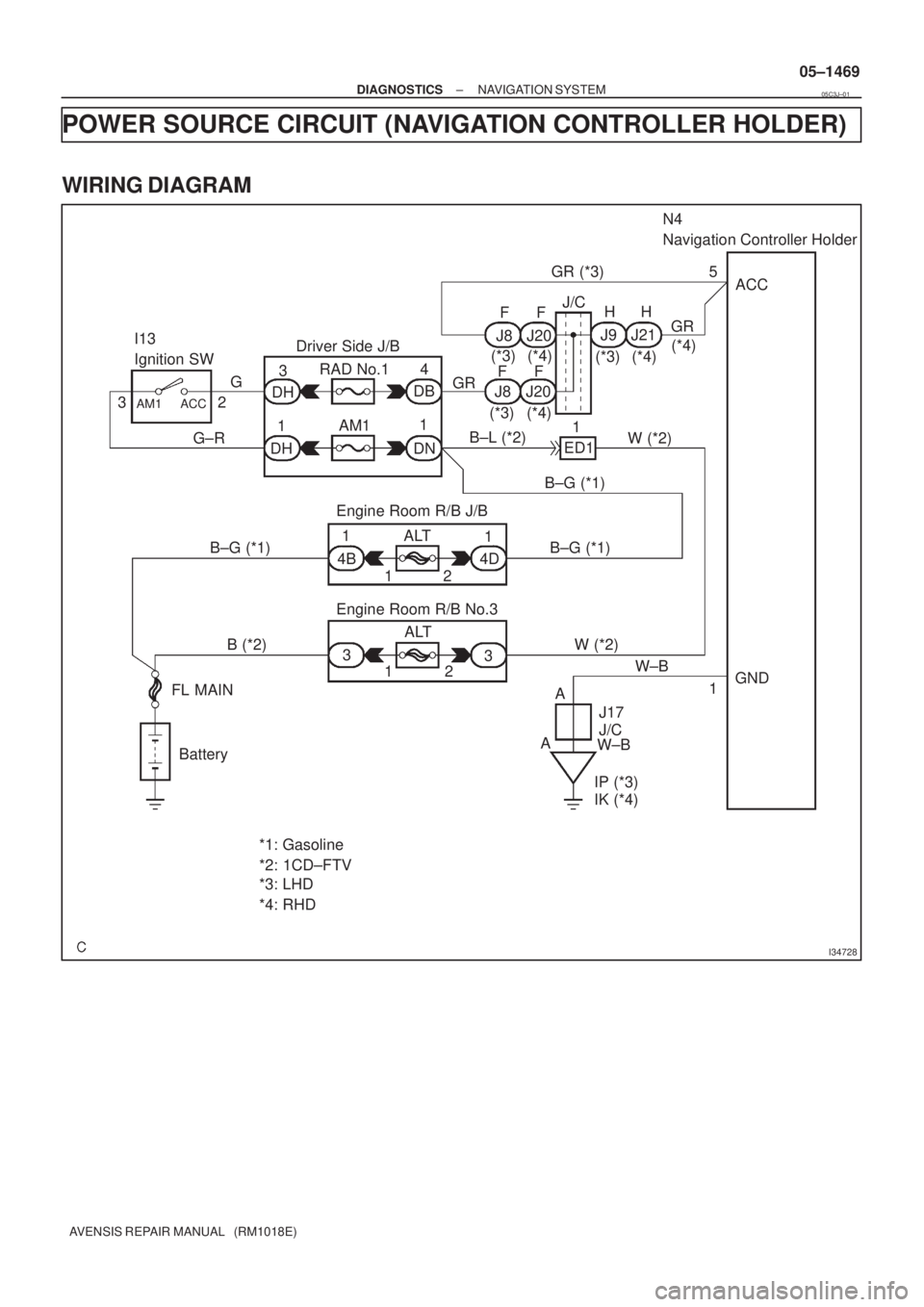
POWER SOURCE CIRCUIT (NAVIGATION CONTROLLER HOLDER)
WIRING DIAGRAM
05C3J±01
Page 1494 of 5135
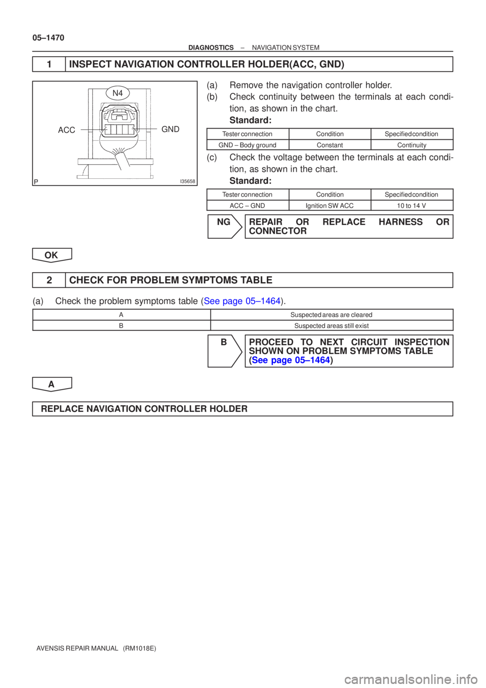
I35658
GND
ACC
N4
05±1470
±
DIAGNOSTICS NAVIGATION SYSTEM
AVENSIS REPAIR MANUAL (RM1018E)
1INSPECT NAVIGATION CONTROLLER HOLDER(ACC, GND)
(a)Remove the navigation controller holder.
(b)Check continuity between the terminals at each condi- tion, as shown in the chart.
Standard:
Tester connectionConditionSpecified condition
GND ± Body groundConstantContinuity
(c)Check the voltage between the terminals at each condi-tion, as shown in the chart.
Standard:
Tester connectionConditionSpecified condition
ACC ± GNDIgnition SW ACC10 to 14 V
NGREPAIR OR REPLACE HARNESS OR CONNECTOR
OK
2CHECK FOR PROBLEM SYMPTOMS TABLE
(a)Check the problem symptoms table (See page 05±1464).
ASuspected areas are cleared
BSuspected areas still exist
B PROCEED TO NEXT CIRCUIT INSPECTION SHOWN ON PROBLEM SYMPTOMS TABLE
(See page 05±1464)
A
REPLACE NAVIGATION CONTROLLER HOLDER
Page 1495 of 5135
I34727
Center J/B
10
CB4
CEL±Y (*3)
L±Y (*4)
(*3) L±YFuse Block
66
21RAD No.2J/C
EE
J24 J25L±Y
(*4)N69Navigation ECU
B±W
B±W+B
Engine Room R/B No.1 and Engine Room J/B No.1
45
IF4 IF1 B±W
(*3) (*4) 1
1
12 1ADCC B (*2)
B±G (*1)
I13
Ignition SW
32
AM1 ACC
G±R34
11 DH
DH DNDB RAD No.1
AM1 GGRDriver Side J/B
FF FF
(*3) (*4)J8 J20
(*3) (*4)J8 J20GR18
N6ACC
B±L (*2) W (*2)
ED11
Engine Room R/B J/B
1
4A
1
4BALT
121
4D B±G (*1) B±G (*1)
B (*2)
B (*2)3
33ALT
12
FL MAIN
Battery
IP W (*2)W (*2)
Center J/B
W±B6
CA13
7
10 CF
CK
CHW±B (*3)
W±B
(*4)7
17 N5
N6SNSE
GND
*1: Gasoline
*2: 1CD±FTV*3: LHD
*4: RHDJ/C
Engine Room R/B No.3
W±B
± DIAGNOSTICSNAVIGATION SYSTEM
05±1467
AVENSIS REPAIR MANUAL (RM1018E)
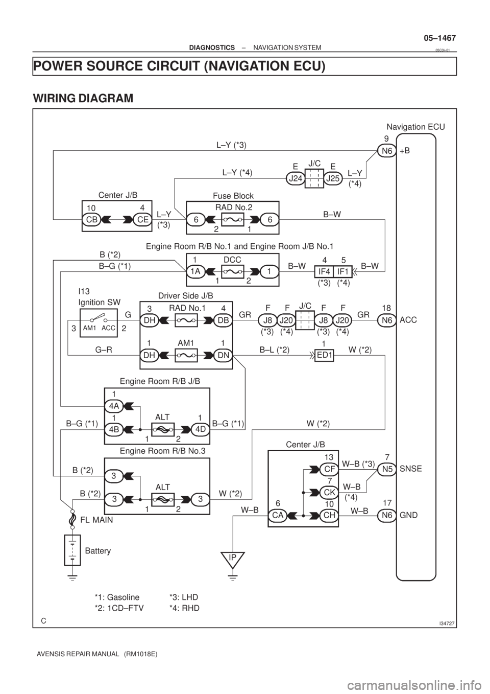
POWER SOURCE CIRCUIT (NAVIGATION ECU)
WIRING DIAGRAM
05C3I±01
Page 1496 of 5135
I32703
+B
ACC
SNSEGND
N5N6
05±1468
±
DIAGNOSTICS NAVIGATION SYSTEM
AVENSIS REPAIR MANUAL (RM1018E)
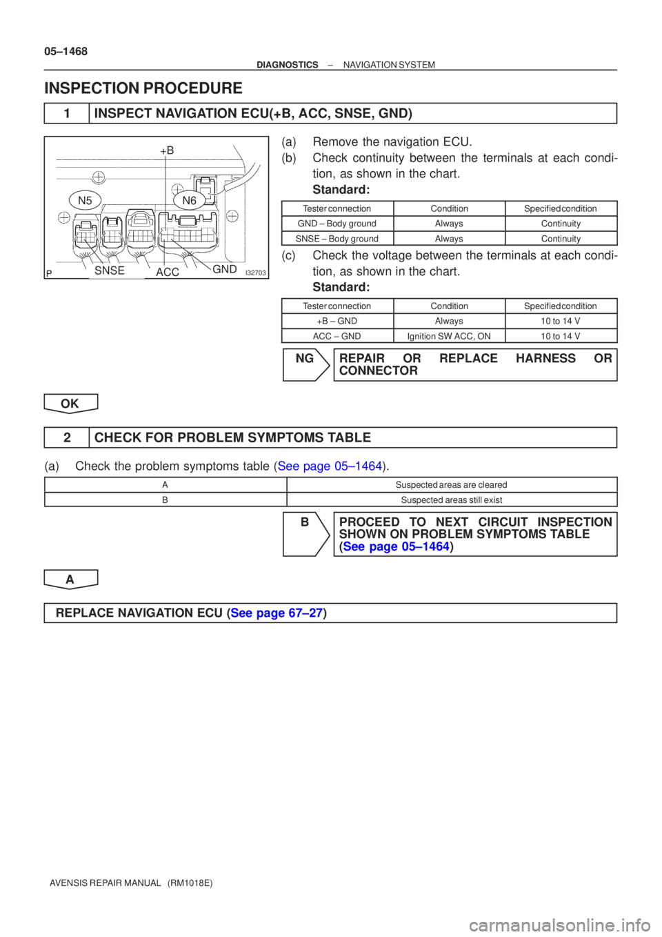
INSPECTION PROCEDURE
1INSPECT NAVIGATION ECU(+B, ACC, SNSE, GND)
(a)Remove the navigation ECU.
(b)Check continuity between the terminals at each condi- tion, as shown in the chart.
Standard:
Tester connectionConditionSpecified condition
GND ± Body groundAlwaysContinuity
SNSE ± Body groundAlwaysContinuity
(c)Check the voltage between the terminals at each condi-
tion, as shown in the chart.
Standard:
Tester connectionConditionSpecified condition
+B ± GNDAlways10 to 14 V
ACC ± GNDIgnition SW ACC, ON10 to 14 V
NGREPAIR OR REPLACE HARNESS OR CONNECTOR
OK
2CHECK FOR PROBLEM SYMPTOMS TABLE
(a)Check the problem symptoms table (See page 05±1464).
ASuspected areas are cleared
BSuspected areas still exist
B PROCEED TO NEXT CIRCUIT INSPECTION SHOWN ON PROBLEM SYMPTOMS TABLE
(See page 05±1464)
A
REPLACE NAVIGATION ECU (See page 67±27)
Page 1497 of 5135
I34729
G±R
I13
Ignition SW
ACC
IG1
ST2 AM2
AM1
G±R
3
41
B±L (*2)
B±G
(*1)
B±RDriver Side J/B
1
DH
DB DH
DH
DNDA
DB 3
5
1AM1
4
9
7 GAUGE1 1
2
53RAD No.1
IG1 RelayGR (*3)
HH F FJ/B
J9 J21 J8 J20
(*3) (*4) (*3) (*4)GR (*4)
GR
GRFF
J8 J20
(*3) (*4)
W±BMulti±display
(CRT Display) Display
14
M1 ACC
R±WCenter J/B
73
CA CFR±W3
M1
M1 15IG
ST1 B±W
Fuse Block
B±Y
6
6
6612
12ST
RAD No.2
B±W L±Y
(*3)L±Y
(*3) Center J/B
49
CE CB
J/C
L±Y
(*4) L±Y (*4)EE
J24 J251
M1
M1+B1
GND1 W±B
W±B25
Center J/B
56
CG CA
W±B
IP IJ B±G
(*1) 1
4A
1
2 1
4D
1
4B B±G (*1)
B±G (*1)ALT Engine Room J/B
1
2ALT
3
3
3 1
ED1B
(*2) B±L
(*2)W
(*2)
B (*2)
B±W
45
IE4 IP1B±W Engine Room R/B No.1 and Engine Room J/B No.1
(*3) (*4)
1
1
IE4 IP1 B±R
B±R
Battery1
11 DCC
AM21 2
1 2B
(*2)
B±G
(*1) 1A
*1: Gasoline
*2: 1CD±FTV*3: LHD
*4: RHD
G±Y
G
2
5
Engine Room R/B No.3
FL
MAIN
± DIAGNOSTICSNAVIGATION SYSTEM
05±1465
AVENSIS REPAIR MANUAL (RM1018E)
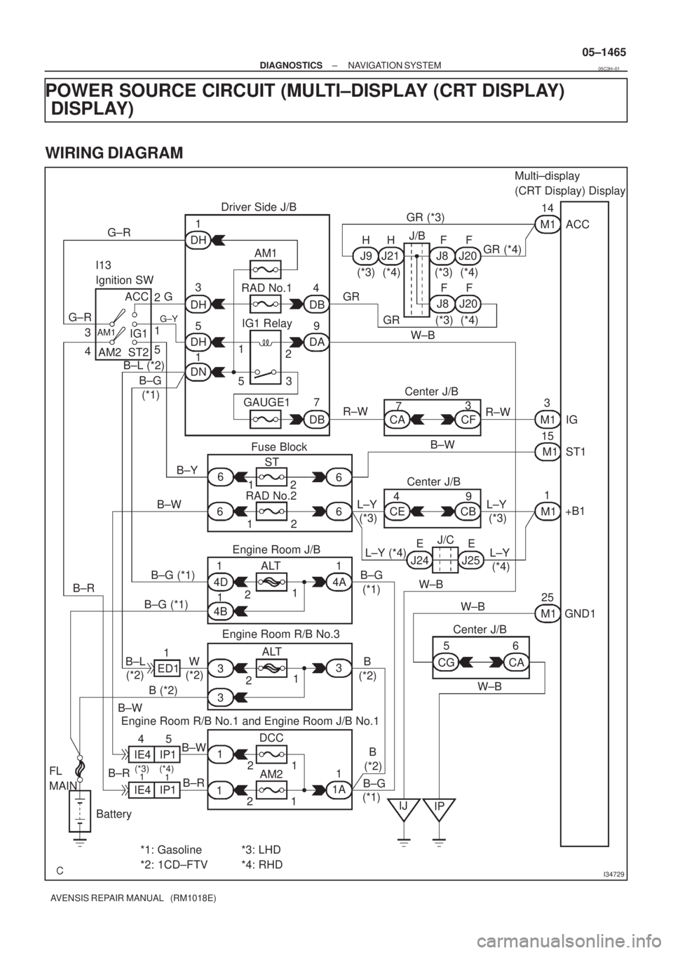
POWER SOURCE CIRCUIT (MULTI±DISPLAY (CRT DISPLAY)
DISPLAY)
WIRING DIAGRAM
05C3H±01
Page 1498 of 5135
I34716
+B1
GND1
ACCST1
IG
M1
05±1466
±
DIAGNOSTICS NAVIGATION SYSTEM
AVENSIS REPAIR MANUAL (RM1018E)
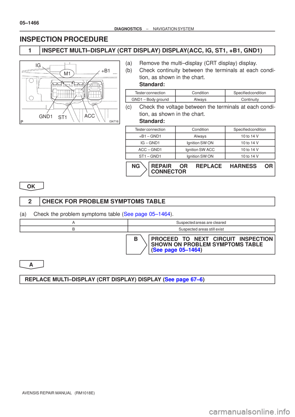
INSPECTION PROCEDURE
1 INSPECT MULTI±DISPLAY (CRT DISPLAY) DISPLAY(ACC, IG, ST1, +B1, GND1)
(a) Remove the multi±display (CRT display) display.
(b) Check continuity between the terminals at each condi- tion, as shown in the chart.
Standard:
Tester connectionConditionSpecified condition
GND1 ± Body groundAlwaysContinuity
(c) Check the voltage between the terminals at each condi-
tion, as shown in the chart.
Standard:
Tester connectionConditionSpecified condition
+B1 ± GND1Always10 to 14 V
IG ± GND1Ignition SW ON10 to 14 V
ACC ± GND1Ignition SW ACC10 to 14 V
ST1 ± GND1Ignition SW ON10 to 14 V
NG REPAIR OR REPLACE HARNESS OR CONNECTOR
OK
2 CHECK FOR PROBLEM SYMPTOMS TABLE
(a)Check the problem symptoms table (See page 05±1464).
ASuspected areas are cleared
BSuspected areas still exist
B PROCEED TO NEXT CIRCUIT INSPECTION SHOWN ON PROBLEM SYMPTOMS TABLE
(See page 05±1464)
A
REPLACE MULTI±DISPLAY (CRT DISPLAY) DISPLAY (See page 67±6)
Page 1499 of 5135
05C3G±01
05±1464
±
DIAGNOSTICS NAVIGATION SYSTEM
AVENSIS REPAIR MANUAL (RM1018E)
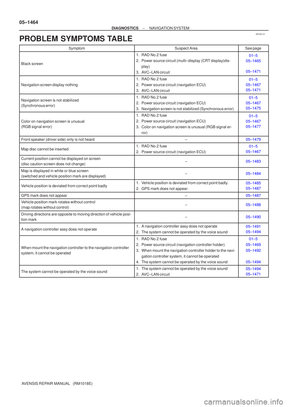
PROBLEM SYMPTOMS TABLE
SymptomSuspect AreaSee page
Black screen
1. RAD No.2 fuse
2. Power source circuit (multi±display (CRT display)dis- play)
3. AVC±LAN circuit01±5
05±1465
05±1471
Navigation screen display nothing
1. RAD No.2 fuse
2. Power source circuit (navigation ECU)
3. AVC±LAN circuit01±5
05±1467
05±1471
Navigation screen is not stabilized
(Synchronous error)1. RAD No.2 fuse
2. Power source circuit (navigation ECU)
3. Navigation screen is not stabilized (Synchronous error)01±5
05±1467
05±1475
Color on navigation screen is unusual
(RGB signal error)
1. RAD No.2 fuse
2. Power source circuit (navigation ECU)
3. Color on navigation screen is unusual (RGB signal er-
ror)01±5
05±1467
05±1477
Front speaker (driver side) only is not heard±05±1479
Map disc cannot be inserted1. RAD No.2 fuse
2. Power source circuit (navigation ECU)01±5
05±1467
Current position cannot be displayed on screen
(disc caution screen does not change)±05±1483
Map is displayed in white or blue screen
(switched and vehicle position mark are displayed)±05±1484
Vehicle position is deviated from correct point badly1. Vehicle position is deviated from correct point badly.
2. GPS mark does not appear.05±1485
05±1487
GPS mark does not appear±05±1487
Vehicle position mark rotates without control
(map rotates without control)±05±1488
Driving directions are opposite to moving direction of vehicle posi-
tion mark±05±1490
A navigation controller assy does not operate1. A navigation controller assy does not operate
2. The system cannot be operated by the voice sound05±1491
05±1494
When mount the navigation controller to the navigation controller
system, it cannot be operated
1. RAD No.2 fuse
2. Power source circuit (navigation controller holder)
3. When mount the navigation controller holder to the navi-
gation controller system, it cannot be operated
4. The system cannot be operated by the voice sound01±5
05±1469
05±1492
05±1494
The system cannot be operated by the voice sound1. The system cannot be operated by the voice sound
2. AVC±LAN circuit05±1494
05±1471
Page 1500 of 5135
05C3X±01
I35876
N4N3N5
± DIAGNOSTICSNAVIGATION SYSTEM
05±1461
AVENSIS REPAIR MANUAL (RM1018E)
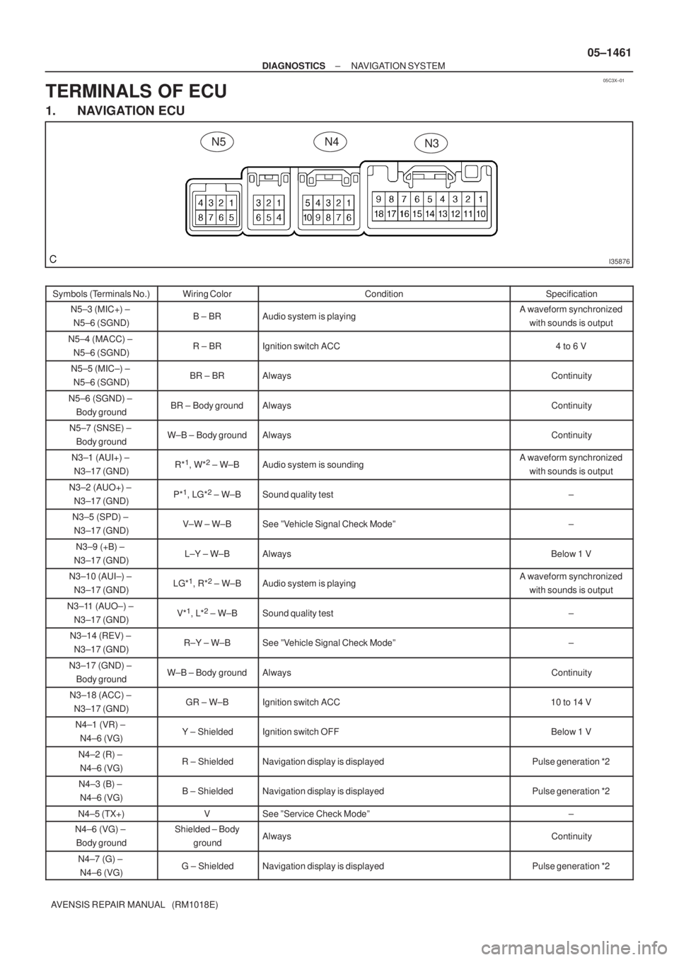
TERMINALS OF ECU
1. NAVIGATION ECU
Symbols (Terminals No.)Wiring ColorConditionSpecification
N5±3 (MIC+) ±
N5±6 (SGND)B ± BRAudio system is playingA waveform synchronized
with sounds is output
N5±4 (MACC) ±
N5±6 (SGND)R ± BRIgnition switch ACC4 to 6 V
N5±5 (MIC±) ±
N5±6 (SGND)BR ± BRAlwaysContinuity
N5±6 (SGND) ±
Body groundBR ± Body groundAlwaysContinuity
N5±7 (SNSE) ±
Body groundW±B ± Body groundAlwaysContinuity
N3±1 (AUI+) ±
N3±17 (GND)R*1, W*2 ± W±BAudio system is soundingA waveform synchronized
with sounds is output
N3±2 (AUO+) ±
N3±17 (GND)P*1, LG*2 ± W±BSound quality test±
N3±5 (SPD) ±
N3±17 (GND)V±W ± W±BSee ºVehicle Signal Check Modeº±
N3±9 (+B) ±
N3±17 (GND)L±Y ± W±BAlwaysBelow 1 V
N3±10 (AUI±) ±
N3±17 (GND)LG*1, R*2 ± W±BAudio system is playingA waveform synchronized
with sounds is output
N3±11 (AUO±) ±
N3±17 (GND)V*1, L*2 ± W±BSound quality test±
N3±14 (REV) ±
N3±17 (GND)R±Y ± W±BSee ºVehicle Signal Check Modeº±
N3±17 (GND) ±
Body groundW±B ± Body groundAlwaysContinuity
N3±18 (ACC) ±
N3±17 (GND)GR ± W±BIgnition switch ACC10 to 14 V
N4±1 (VR) ±
N4±6 (VG)Y ± ShieldedIgnition switch OFFBelow 1 V
N4±2 (R) ±
N4±6 (VG)R ± ShieldedNavigation display is displayedPulse generation *2
N4±3 (B) ±
N4±6 (VG)B ± ShieldedNavigation display is displayedPulse generation *2
N4±5 (TX+)VSee ºService Check Modeº±
N4±6 (VG) ±
Body groundShielded ± Body
groundAlwaysContinuity
N4±7 (G) ±
N4±6 (VG)G ± ShieldedNavigation display is displayedPulse generation *2