display TOYOTA AYGO X 2022 (in English) Manual PDF
[x] Cancel search | Manufacturer: TOYOTA, Model Year: 2022, Model line: AYGO X, Model: TOYOTA AYGO X 2022Pages: 494, PDF Size: 92.53 MB
Page 210 of 494
208
Owner's Manual_Europe_M99V08_en
4-5. Using the driving support systems
●When driving on a narrow road
●When driving toward a banner, flag, low-hanging branch or boom barrier
(such as those used at railroad cross- ings, toll gates and parking lots)
●When there is a rut or hole in the sur-face of the road
●When driving on a metal cover (grat-ing), such as those used for drainage ditches
●When driving up or down a steep slope
●If a sensor is hit by a large amount of water, such as when driving on a
flooded road
●There is dirt, snow, water drops or ice
on a sensor. (Cleaning the sensors will resolve this problem.)
●A sensor is coated with a sheet of spray or heavy rain
●When driving in inclement weather such as fog, snow or a sandstorm
●When strong winds are blowing
●When vehicle horns, vehicle detec-
tors, motorcycle engines, air brakes of large vehicles, the clearance sonar of other vehicles or other devices which
produce ultrasonic waves are near the vehicle
●If the front of the vehicle is raised or
lowered due to the carried load
●If the orientation of a sensor has been changed due to a collision or other
impact
●The vehicle is approaching a tall or
curved curb
●Driving close to columns (H-shaped
steel beams, etc.) in multi-story park- ing garages, construction sites, etc.
●If the vehicle cannot be driven in a stable manner, such as when the vehicle has been in an accident or is
malfunctioning
●On an extremely bumpy road, on an
incline, on gravel, or on grass
●When a tire chains, compact spare tire
or an emergency tire puncture repair kit is used
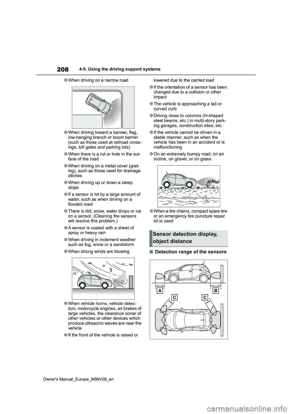
■Detection range of the sensors
Sensor detection display,
object distance
Page 211 of 494
209
4
Owner's Manual_Europe_M99V08_en
4-5. Using the driving support systems
Driving
Approximately 100 cm (3.3 ft.)
Approximately 150 cm (4.9 ft.)
Approximately 60 cm (2.0 ft.)
The diagram shows the detection range
of the sensors. Note that the sensors
cannot detect objects that are
extremely close to the vehicle.
The range of the sensors may change
depending on the shape of the object,
etc.
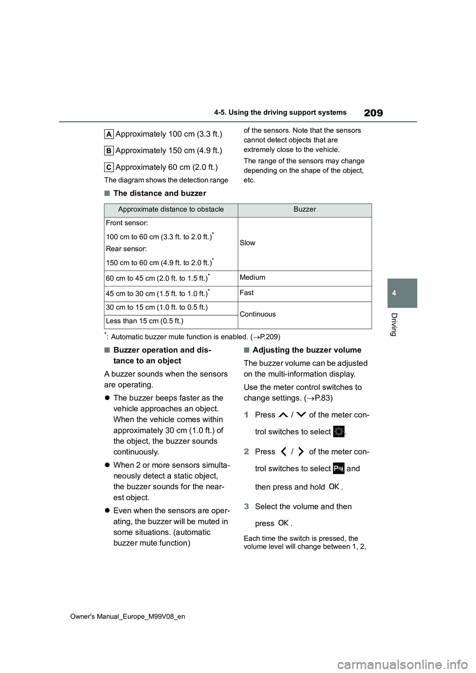
■The distance and buzzer
*: Automatic buzzer mute function is enabled. ( P.209)
■Buzzer operation and dis-
tance to an object
A buzzer sounds when the sensors
are operating.
The buzzer beeps faster as the
vehicle approaches an object.
When the vehicle comes within
approximately 30 cm (1.0 ft.) of
the object, the buzzer sounds
continuously.
When 2 or more sensors simulta-
neously detect a static object,
the buzzer sounds for the near-
est object.
Even when the sensors are oper-
ating, the buzzer will be muted in
some situations. (automatic
buzzer mute function)
■Adjusting the buzzer volume
The buzzer volume can be adjusted
on the multi-information display.
Use the meter control switches to
change settings. ( P. 8 3 )
1 Press / of the meter con-
trol switches to select .
2 Press / of the meter con-
trol switches to select and
then press and hold .
3 Select the volume and then
press .
Each time the switch is pressed, the volume level will change between 1, 2,
Approximate distance to obstacleBuzzer
Front sensor:
100 cm to 60 cm (3.3 ft. to 2.0 ft.)*
Rear sensor:
150 cm to 60 cm (4.9 ft. to 2.0 ft.)*
Slow
60 cm to 45 cm (2.0 ft. to 1.5 ft.)*Medium
45 cm to 30 cm (1.5 ft. to 1.0 ft.)*Fast
30 cm to 15 cm (1.0 ft. to 0.5 ft.)ContinuousLess than 15 cm (0.5 ft.)
Page 212 of 494
210
Owner's Manual_Europe_M99V08_en
4-5. Using the driving support systems
and 3.
■Muting a buzzer
A mute button will be displayed on
the multi-information display when
an object is detected. To mute the
buzzer, press .
The buzzers for the Toyota parking
assist-sensor will be muted simulta-
neously.
Mute will be canceled automatically
in the following situations:
When the shift lever is changed.
When the vehicle speed exceeds
a certain speed.
When there is a malfunction in a
sensor or the system is tempo-
rarily unavailable.
When the operating function is
disabled manually.
When the engine switch is turned
off.
*: If equipped
■If “Exhaust Filter Full See Owner’s Manual” is shown on the multi-
information display
●The message may be displayed while
high load driving with particulate mat- ter accumulating.
●Engine output (engine speed) is restricted when a certain amount of particulate matter accumulates, how-
ever, it is possible to drive the vehicle unless the malfunction indicator lamp comes on.
●Particulate matter can accumulate more quickly if the vehicle is fre-
quently driven short trips or at low speeds, or if the engine is regularly started in an extremely cold environ-
ment. Excessive accumulation of par- ticulate matter can be prevented by periodically driving long distances
continuously with intermittent releas- ing of the accelerator pedal, such as when driving on highways and free-
ways.
■If the malfunction indicator lamp comes on or “Engine Maintenance Required Visit Your Dealer” is
shown on the multi-information display
The amount of accumulated particulate
matter has exceeded a certain level. Have the vehicle inspected by any
GPF (Gasoline Particu-
late Filter) system*
The GPF system collects par-
ticulate matter in the exhaust
gas by using an exhaust gas
filter.
The system will operate to
regenerate the filter automati-
cally, depending on the vehicle
conditions.
Page 214 of 494
212
Owner's Manual_Europe_M99V08_en
4-5. Using the driving support systems
drifting to the outer side by perform-
ing inner wheel brake control when
attempting to accelerate while turn-
ing
■Hill-start assist control
Helps to reduce the backward
movement of the vehicle when
starting on an uphill
■EPS (Electric Power Steering)
Employs an electric motor to
reduce the amount of effort needed
to turn the steering wheel.
■Emergency brake signal
When the brakes are applied sud-
denly, the emergency flashers auto-
matically flash to alert the vehicle
behind.
■Secondary Collision Brake
When the SRS airbag sensor
detects a collision and the system
operates, the brakes and brake
lights are automatically controlled
to reduce the vehicle speed and
help reduce the possibility of further
damage due to a secondary colli-
sion.
■When the TRC/VSC systems are
operating
The slip indicator light will flash while the TRC/VSC systems are operating.
■Disabling the TRC system
If the vehicle gets stuck in mud, dirt or
snow, the TRC system may reduce
power from the engine to the wheels.
Pressing to turn the system off may
make it easier for you to rock the vehicle
in order to free it.
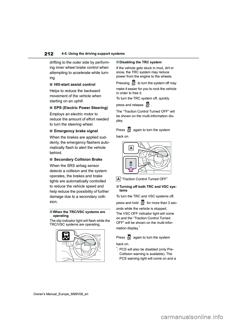
To turn the TRC system off, quickly
press and release .
The “Traction Control Turned OFF” will
be shown on the multi-information dis-
play.
Press again to turn the system
back on.
“Traction Control Turned OFF”
■Turning off both TRC and VSC sys- tems
To turn the TRC and VSC systems off,
press and hold for more than 3 sec-
onds while the vehicle is stopped.
The VSC OFF indicator light will come
on and the “Traction Control Turned
OFF” will be shown on the multi-infor-
mation display.*
Press again to turn the system
back on.
*: PCS will also be disabled (only Pre-
Collision warning is available). The
PCS warning light will come on and a
Page 215 of 494
213
4
Owner's Manual_Europe_M99V08_en
4-5. Using the driving support systems
Driving
message will be displayed on the
multi-information display. ( P.171)
■When the message is displayed on
the multi-information display show-
ing that TRC has been disabled
even if has not been pressed
TRC is temporary deactivated. If the
information continues to show, contact any authorized Toyota retailer or Toyota authorized repairer, or any reliable
repairer.
■Operating conditions of hill-start assist control
When all of the following conditions are
met, the hill-start assist control will oper- ate:
●Vehicles with Multidrive: The shift lever is in a position other than P or N (when starting off forward/backward
on an upward incline).
●Vehicles with manual transmission:
The shift lever is in a position other than R when starting off forward on an upward incline, or the shift lever is in
R when starting off backward on an upward incline.
●The vehicle is stopped
●The accelerator pedal is not
depressed
●The parking brake is not engaged
●The engine switch is turned to ON
■Automatic system cancelation of hill-start assist control
The hill-start assist control will turn off in any of the following situations:
●Vehicles with Multidrive: The shift lever is shifted to P or N.
●Vehicles with manual transmission: The shift lever is shifted to R when starting off forward on an upward
incline, or the shift lever is shifted to other than R when starting off back-ward on an upward incline.
●The accelerator pedal is depressed
●The parking brake is engaged
●2 seconds at maximum elapsed after the brake pedal is released
●The engine switch is turned to OFF
■Sounds and vibrations caused by the ABS, brake assist, VSC, TRC
and hill-start assist control sys- tems
●A sound may be heard from the engine compartment when the brake pedal is depressed repeatedly, when
the engine is started or just after the vehicle begins to move. This sound does not indicate that a malfunction
has occurred in any of these systems.
●Any of the following conditions may
occur when the above systems are operating. None of these indicates that a malfunction has occurred.
• Vibrations may be felt through the vehicle body and steering.• A motor sound may be heard also
after the vehicle comes to a stop. • The brake pedal may pulsate slightly after the ABS is activated.
• The brake pedal may move down slightly after the ABS is activated.
■Active Cornering Assist operation sounds and vibrations
When the Active Cornering Assist is operated, operation sounds and vibra-tions may be generated from the brake
system, but this is not a malfunction.
■EPS operation sound
When the steering wheel is operated, a motor sound (whirring sound) may be
heard. This does not indicate a malfunc- tion.
■Automatic reactivation of TRC and VSC systems
After turning the TRC and VSC systems off, the systems will be automatically re-enabled in the following situations:
●When the engine switch is turned off
●If only the TRC system is turned off, the TRC will turn on when vehicle speed increases.
Page 222 of 494
220
Owner's Manual_Europe_M99V08_en
5-1. Using the air conditioning system and defogger
5-1.Using the a ir c onditioning sys te m and de fog ger
*: If equipped
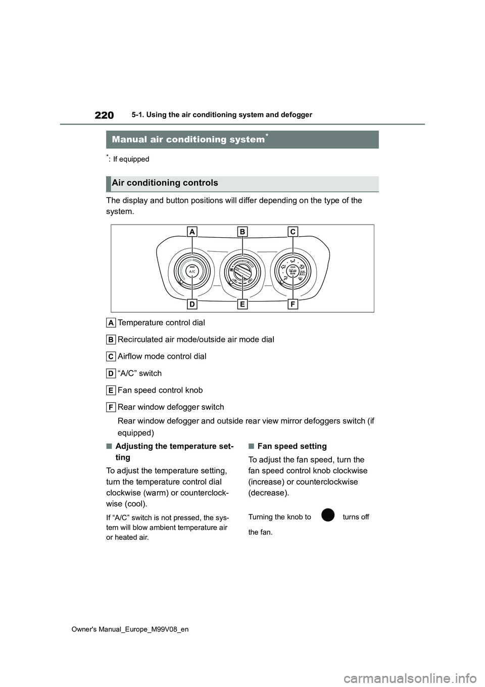
The display and button positions will differ depending on the type of the
system.
Temperature control dial
Recirculated air mode/outside air mode dial
Airflow mode control dial
“A/C” switch
Fan speed control knob
Rear window defogger switch
Rear window defogger and outside rear view mirror defoggers swi tch (if
equipped)
■Adjusting the temperature set-
ting
To adjust the temperature setting,
turn the temperature control dial
clockwise (warm) or counterclock-
wise (cool).
If “A/C” switch is not pressed, the sys-
tem will blow ambient temperature air
or heated air.
■Fan speed setting
To adjust the fan speed, turn the
fan speed control knob clockwise
(increase) or counterclockwise
(decrease).
Turning the knob to turns off
the fan.
Manual air conditioning system*
Air conditioning controls
Page 226 of 494
224
Owner's Manual_Europe_M99V08_en
5-1. Using the air conditioning system and defogger
*: If equipped
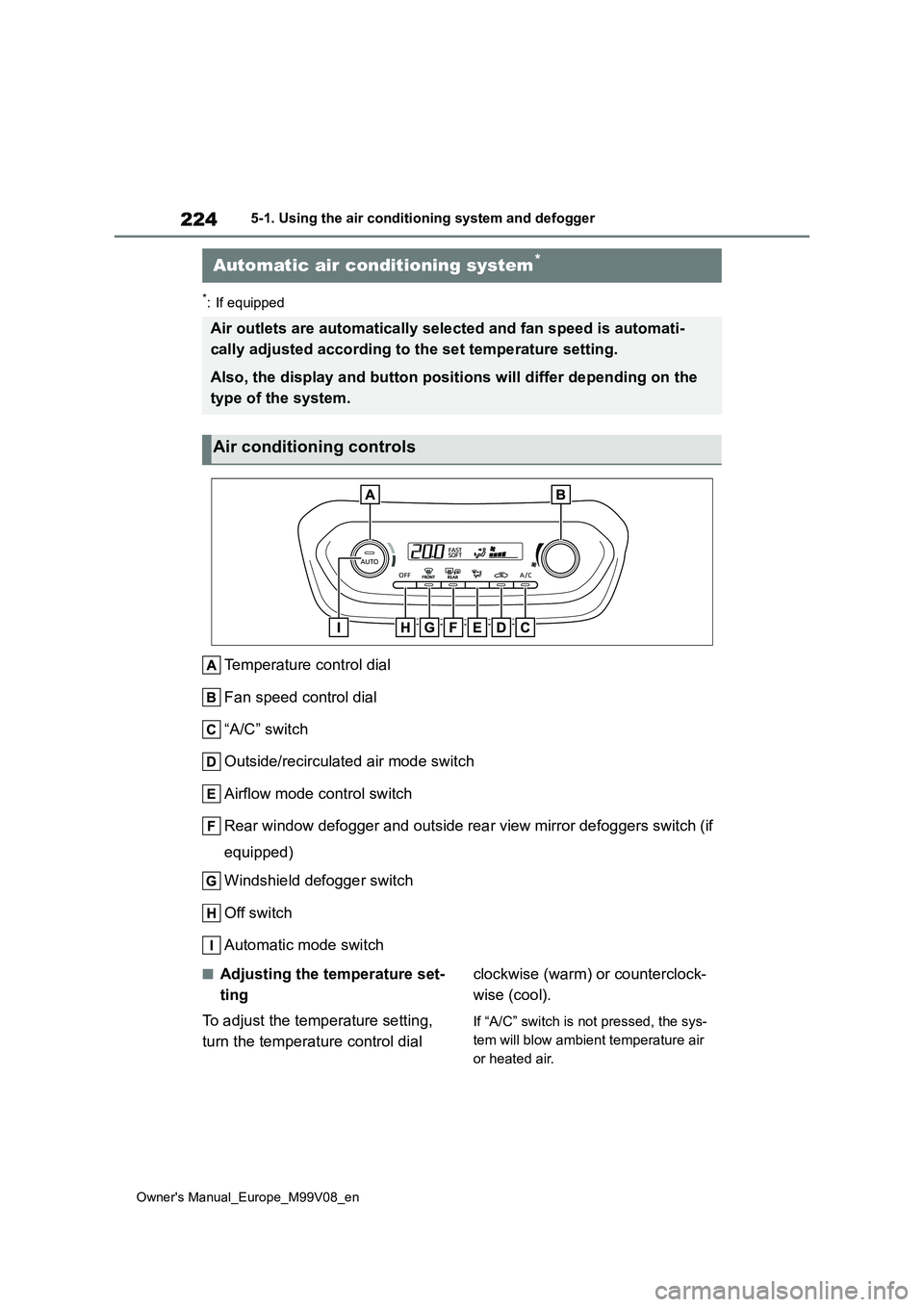
Temperature control dial
Fan speed control dial
“A/C” switch
Outside/recirculated air mode switch
Airflow mode control switch
Rear window defogger and outside rear view mirror defoggers swi tch (if
equipped)
Windshield defogger switch
Off switch
Automatic mode switch
■Adjusting the temperature set-
ting
To adjust the temperature setting,
turn the temperature control dial
clockwise (warm) or counterclock-
wise (cool).
If “A/C” switch is not pressed, the sys-
tem will blow ambient temperature air
or heated air.
Automatic air conditioning system*
Air outlets are automatically selected and fan speed is automat i-
cally adjusted according to the set temperature setting.
Also, the display and button positions will differ depending on the
type of the system.
Air conditioning controls
Page 242 of 494
240
Owner's Manual_Europe_M99V08_en
5-4. Other interior features
wireless charger, the call sensitivity
and communication speed may be reduced.
■Operation sounds
When the power supply is turned on,
while searching for the portable device a sound will be produced, however this is not a malfunction.
■Cleaning the wireless charger
P. 2 4 8
WARNING
■Caution while driving
When charging a portable device, for
safety reasons, the driver should not operate the main part of the portable device while driving.
■Caution regarding interference with electronic devices
People with implantable cardiac pace- makers, cardiac resynchronization therapy-pacemakers or implantable
cardioverter defibrillators, as well as any other electrical medical device, should consult their physician about
the usage of the wireless charger. The operations of the wireless char-ger may have an affect on medical
devices.
■To prevent damage or burns
Observe the following precautions. Failure to do so may result in a possi-bility of equipment failure and dam-
age, catch fire, burns due to overheat.
●Do not insert any metallic objects
between the charging area and the portable device while charging
●Do not attach stickers, metallic objects, etc., to the charger area or portable device
●Do not cover with cloth, etc., and charge
●Do not charge portable devices other than designated
●Do not attempt to dismantle for dis-assembly or modifications
●Do not hit or apply a strong force
NOTICE
■Conditions in which the function may not operate correctly
In the following conditions, it may not operate correctly
●The portable device is fully charged
●There is foreign matter between the
charge area and portable device
●The temperature of the portable
device gets higher from charging
●The charging surface of the porta-
ble device is facing up
●The placement of the portable
device is out of alignment with the charge area
●Near a TV tower, electric power plant, gas station, radio station, large display, airport or other facility
that generates strong radio waves or electrical noise
●When the portable device is in con-tact with, or is covered by the fol-lowing metallic objects
• Cards to which aluminum foil is attached
• Cigarette boxes that have alumi- num foil inside
• Metallic wallets or bags
•Coins
• Hand warmers made of metal
• Media such as CDs and DVDs
Page 262 of 494
260
Owner's Manual_Europe_M99V08_en
6-3. Do-it-yourself maintenance
●When the engine is new, for example
directly after purchasing the vehicle or after replacing the engine
●If low quality oil or oil of an inappropri-ate viscosity is used
●When driving at high engine speeds or with a heavy load, when towing (vehicles with towing packages), or
when driving while accelerating or decelerating frequently
●When leaving the engine idling for a long time, or when driving frequently through heavy traffic
■After changing the engine oil
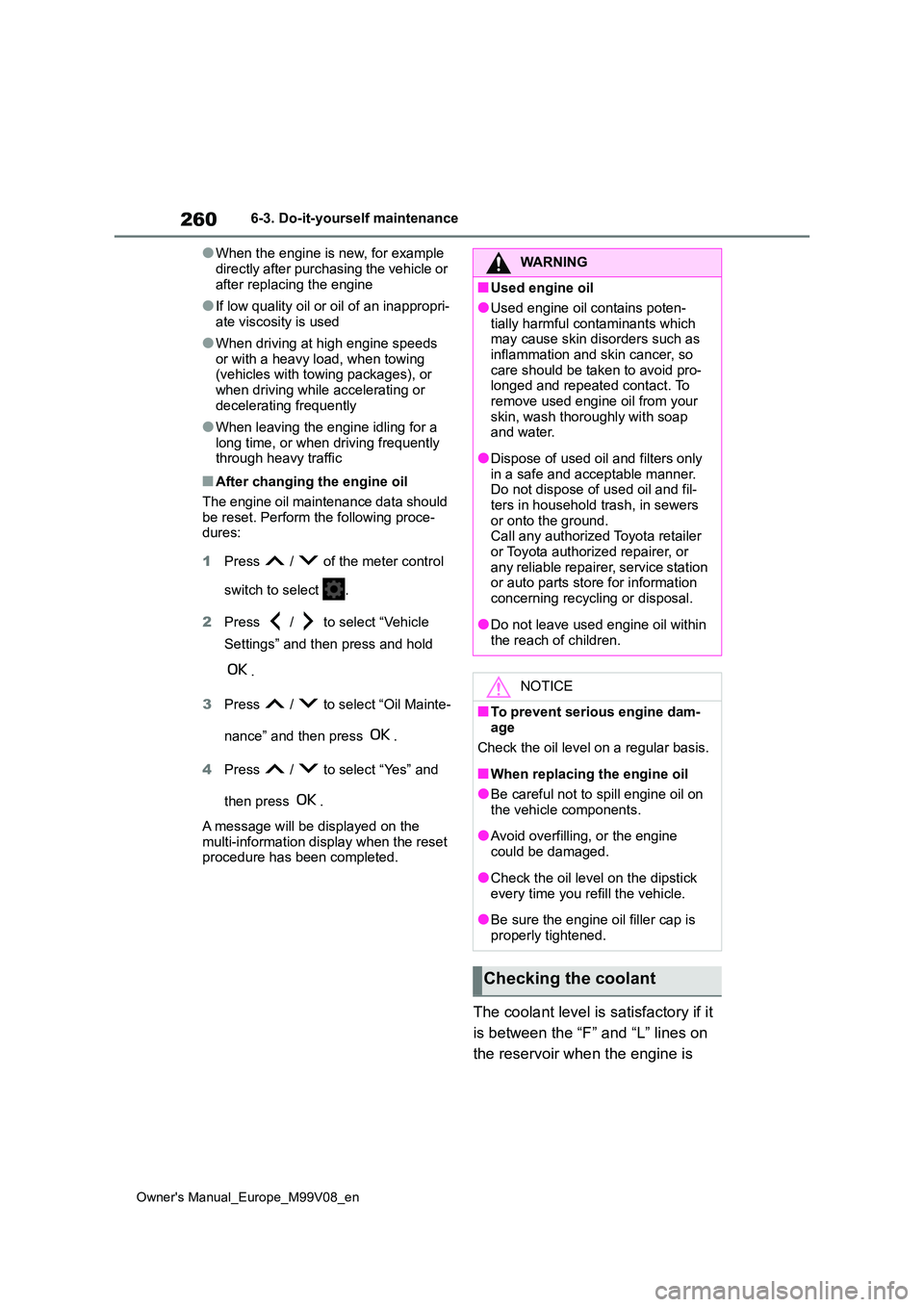
The engine oil maintenance data should be reset. Perform the following proce-dures:
1 Press / of the meter control
switch to select .
2 Press / to select “Vehicle
Settings” and then press and hold
.
3 Press / to select “Oil Mainte-
nance” and then press .
4 Press / to select “Yes” and
then press .
A message will be displayed on the
multi-information display when the reset procedure has been completed.
The coolant level is satisfactory if it
is between the “F” and “L” lines on
the reservoir when the engine is
WARNING
■Used engine oil
●Used engine oil contains poten-
tially harmful contaminants which may cause skin disorders such as inflammation and skin cancer, so
care should be taken to avoid pro- longed and repeated contact. To remove used engine oil from your
skin, wash thoroughly with soap and water.
●Dispose of used oil and filters only in a safe and acceptable manner. Do not dispose of used oil and fil-
ters in household trash, in sewers or onto the ground.Call any authorized Toyota retailer
or Toyota authorized repairer, or any reliable repairer, service station or auto parts store for information
concerning recycling or disposal.
●Do not leave used engine oil within
the reach of children.
NOTICE
■To prevent serious engine dam- age
Check the oil level on a regular basis.
■When replacing the engine oil
●Be careful not to spill engine oil on
the vehicle components.
●Avoid overfilling, or the engine
could be damaged.
●Check the oil level on the dipstick
every time you refill the vehicle.
●Be sure the engine oil filler cap is
properly tightened.
Checking the coolant
Page 306 of 494
304
Owner's Manual_Europe_M99V08_en
7-2. Steps to take in an emergency
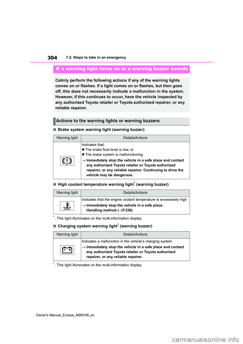
■Brake system warning light (warning buzzer)
■High coolant temperature warning light* (warning buzzer)
*: This light illuminates on the multi-information display.
■Charging system warning light* (warning buzzer)
*: This light illuminates on the multi-information display.
If a warning light turns on or a warning buzzer sounds
Calmly perform the following actions if any of the warning lights
comes on or flashes. If a light comes on or flashes, but then g oes
off, this does not necessarily indicate a malfunction in the sy stem.
However, if this continues to o ccur, have the vehicle inspected by
any authorized Toyota retailer or Toyota authorized repairer, o r any
reliable repairer.
Actions to the warning lights or warning buzzers
Warning lightDetails/Actions
Indicates that:
The brake fluid level is low; or
The brake system is malfunctioning
Immediately stop the vehicle in a safe place and contact
any authorized Toyota retailer or Toyota authorized
repairer, or any reliable repairer. Continuing to drive the
vehicle may be dangerous.
Warning lightDetails/Actions
Indicates that the engine coolant temperature is excessively hi gh
Immediately stop the vehicle in a safe place.
Handling method ( P.339)
Warning lightDetails/Actions
Indicates a malfunction in the vehicle’s charging system
Immediately stop the vehicle in a safe place and contact
any authorized Toyota retailer or Toyota authorized
repairer, or any reliable repairer.