Multimedia system TOYOTA BZ4X 2022 Owners Manual (in English)
[x] Cancel search | Manufacturer: TOYOTA, Model Year: 2022, Model line: BZ4X, Model: TOYOTA BZ4X 2022Pages: 674, PDF Size: 120.02 MB
Page 18 of 674
16
Owners Manual_Europe_M42D76_en
Pictorial index
When the warning messages are displayed ........................ ............P.523
Turn signal lever .............................................. ..............................P.253
Headlight switch ............................................... .............................P.259
Headlights/front position lights/tail lights/license plate ligh ts/
daytime running lights ......................................... .............................P.259
Rear fog light................................................. ...................................P.268
Windshield wiper and washer switch ............................. .............P.269
Usage.......................................................... .....................................P.269
Adding washer fluid............................................ ..............................P.475
Headlight cleaners*1............................................................... .........P.269
Warning messages ............................................... ...........................P.523
Emergency flasher switch....................................... ......................P.506
Hood lock release lever ........................................ .........................P.467
Tilt and telescopic steering lock release lever................ ............P.215
Adjustment ..................................................... ..................................P.215
Air conditioning system ........................................ ........................P.420
Usage.......................................................... .....................................P.420
Rear window defogger ........................................... ..........................P.422
Multimedia system*2
*1: If equipped
*2: Refer to “Multimedia owner’s manual”.
Page 26 of 674
24
Owners Manual_Europe_M42D76_en
Pictorial index
When the warning messages are displayed ........................ ............P.523
Turn signal lever .............................................. ..............................P.253
Headlight switch ............................................... .............................P.259
Headlights/front position lights/tail lights/license plate ligh ts/
daytime running lights ......................................... .............................P.259
Rear fog light................................................. ...................................P.268
Windshield wiper and washer switch ............................. .............P.269
Usage.......................................................... .....................................P.269
Adding washer fluid............................................ ..............................P.475
Headlight cleaners ............................................. ..............................P.269
Warning messages ............................................... ...........................P.523
Emergency flasher switch....................................... ......................P.506
Hood lock release lever ........................................ .........................P.467
Tilt and telescopic steering lock release lever................ ............P.215
Adjustment ..................................................... ..................................P.215
Air conditioning system ........................................ ........................P.420
Usage.......................................................... .....................................P.420
Rear window defogger ........................................... ..........................P.422
Multimedia system*
*: Refer to “Multimedia owner’s manual”.
Page 28 of 674
26
Owners Manual_Europe_M42D76_en
Pictorial index
Power back door switch*1.............................................................P. 193
Automatic High Beam switch*1.....................................................P.265
Adaptive High-beam System switch*1..........................................P.262
Headlight leveling dial*1............................................................... .P.261
“ODO TRIP” switch .............................................. ..........................P.174
Instrument panel light control switches ........................ ..............P.175
*1: If equipped
*2: Refer to “Multimedia owner’s manual”.
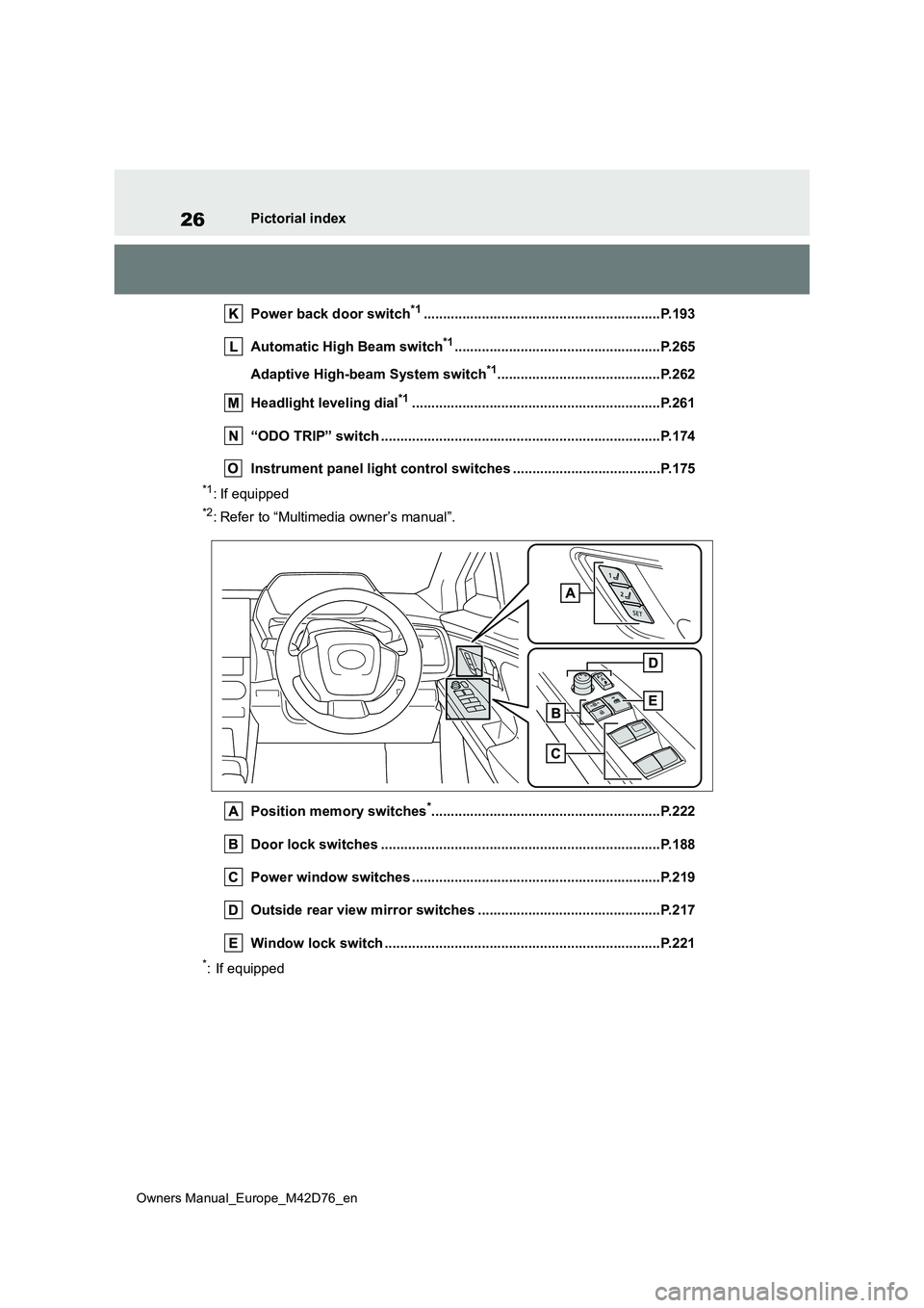
Position memory switches*...........................................................P.22 2
Door lock switches ............................................. ...........................P.188
Power window switches .......................................... ......................P.219
Outside rear view mirror switches .............................. .................P.217
Window lock switch ............................................. ..........................P.221
*: If equipped
Page 127 of 674
125
2
Owners Manual_Europe_M42D76_en
2-2. Charging
Electric Vehicle system
The “Charging Settings” screen will be
displayed.
4 Press or of the meter control
switches to select “Charging Limit”,
and then press .
The “Charging Limit” screen will be dis- played.
5 Select “Full”, “90%”, “80%”, “70%”,
“60%” or “50%” and then press .
●Setting operations on multimedia
1 Select .
2 Select “Vehicle customize”.
3 Select “Charging”.
4 Select “Charging limit”.
5 Select “Full”, “90%”, “80%”, “70%”, “60%” or “50%”.
If the setting is changed during DC charging, charging may stop due to the operation of the DC charger timer and
the traction battery cannot be fully charged.
■Protection function of AC charging inlet overheating
By installing a temperature sensor to the AC charging inlet, prevents parts from melting when the temperature rises due
to foreign matter entering the charging connector.
When a certain temperature increase is
detected, charging is stopped immedi- ately.
After this, when the power switch is off,
a message will be displayed on the multi-information display ( P.160)
WARNING
■When charging
Observe the following precautions.
Failure to do so may cause an unex- pected accident, resulting in death or serious injury.
●Connect to a power source suitable for charging. ( P.112)
●Check that the AC charging cable, plug and socket are free of foreign matter.
●Before charging, check that the AC charging inlet is not deformed,
damaged or corroded, and check that the inlet is free of foreign mat-ter such as dirt, snow and ice.
If there is dirt or dust in these areas, remove completely before inserting the charging connector.
●Before inserting the charging plug into the charger, make sure there is
no dirt or dust on the terminal areas. If there is dirt or dust in these areas, remove completely before
inserting the charging plug.
●Do not get the terminals of the AC
charging inlet wet.
●Only use sockets where the plug
can be securely inserted.
●Do not bundle or wind the AC
charging cable while charging, as doing so may result in overheating.
●Do not touch the terminals of the charging connector and AC charging inlet with a sharp metal
objects (needles, etc.,) or hands, or short them with foreign objects.
Page 132 of 674
130
Owners Manual_Europe_M42D76_en
2-2. Charging
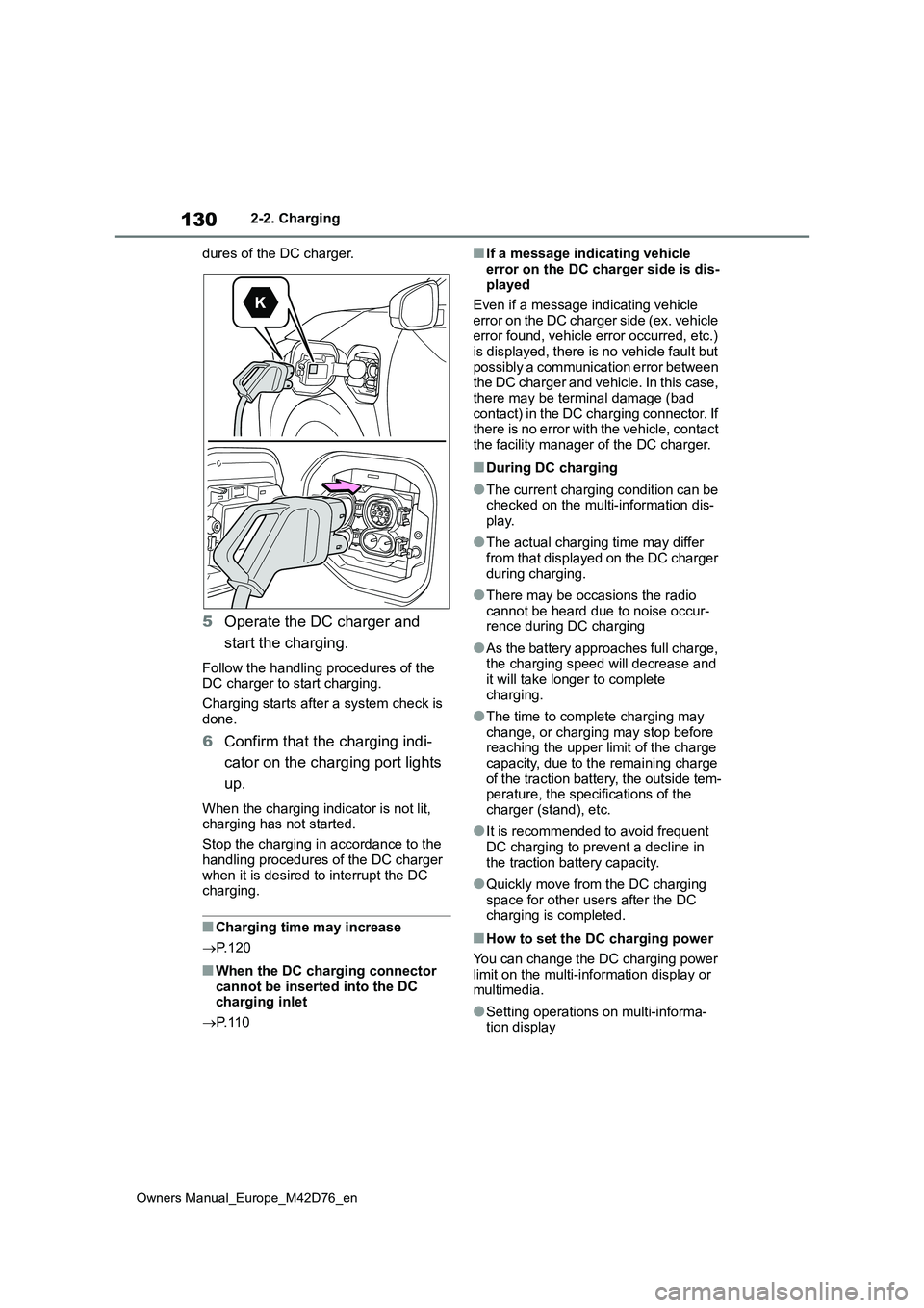
dures of the DC charger.
5 Operate the DC charger and
start the charging.
Follow the handling procedures of the DC charger to start charging.
Charging starts after a system check is
done.
6 Confirm that the charging indi-
cator on the charging port lights
up.
When the charging indicator is not lit, charging has not started.
Stop the charging in accordance to the
handling procedures of the DC charger when it is desired to interrupt the DC charging.
■Charging time may increase
P. 1 2 0
■When the DC charging connector cannot be inserted into the DC charging inlet
P. 1 1 0
■If a message indicating vehicle
error on the DC charger side is dis- played
Even if a message indicating vehicle
error on the DC charger side (ex. vehicle error found, vehicle error occurred, etc.) is displayed, there is no vehicle fault but
possibly a communication error between the DC charger and vehicle. In this case, there may be terminal damage (bad
contact) in the DC charging connector. If there is no error with the vehicle, contact the facility manager of the DC charger.
■During DC charging
●The current charging condition can be checked on the multi-information dis-
play.
●The actual charging time may differ
from that displayed on the DC charger during charging.
●There may be occasions the radio cannot be heard due to noise occur-rence during DC charging
●As the battery approaches full charge, the charging speed will decrease and
it will take longer to complete charging.
●The time to complete charging may change, or charging may stop before reaching the upper limit of the charge
capacity, due to the remaining charge of the traction battery, the outside tem-perature, the specifications of the
charger (stand), etc.
●It is recommended to avoid frequent
DC charging to prevent a decline in the traction battery capacity.
●Quickly move from the DC charging space for other users after the DC charging is completed.
■How to set the DC charging power
You can change the DC charging power limit on the multi-information display or multimedia.
●Setting operations on multi-informa-tion display
Page 133 of 674
131
2
Owners Manual_Europe_M42D76_en
2-2. Charging
Electric Vehicle system
1Press or of the meter control
switches to select .
2 Press or of the meter control
switches to select “Vehicle Settings”,
and then press and hold .
3 Press or of the meter control
switches to select “Charging Set-
tings”, and then press .
The “Charging Settings” screen will be displayed.
4 Press or of the meter control
switches to select “DC charging
power”, and then press .
The “DC charging power” screen will be displayed.
5 Press or of the meter control
switches to select the charging
power from “MAX”, “125kW”,
“100kW”, “75kW”, “50kW” and then
press .
*The maximum power when charging is
limited to the selected power or less.
If “MAX” is selected, the vehicle will be charged with the maximum power that
can be charged.
●Setting operations on multimedia
1 Select .
2 Select “Vehicle customize”.
3 Select “Charging”.
4 Select “DC charging power”.
5 Select from “MAX”, “125kW”,
“100kW”, “75kW”, “50kW”.
*The maximum power when charging is limited to the selected power or less.
If “MAX” is selected, the vehicle will be charged with the maximum power that can be charged.
■Changing the “Charging Limit” set-
tings
P. 1 2 4
■If “Check Charging System Close Charging Port Lid See Owner’s
Manual” is displayed on the multi- information display
If the system check after DC charging is
not completed successfully, the EV sys- tem will not start even if the power switch is pressed while depressing the
brake pedal.
Perform a system check with the follow- ing procedures.
1 Be sure to engage the parking brake
and then turn the power switch off.
2 Close the charging inlet cap, close the charging port lid.
3 Check if “Checking Charging Sys- tem” is displayed on the multi-infor-
mation display when the power switch is turned to ON.
Do not open the charging port lid while
the charging system is checking.
When the system check is completed, the power switch automatically turns off.
4 Press the power switch while
depressing the brake pedal. The “READY” indicator turns on.
Contact any authorized Toyota retailer
or Toyota authorized repairer, or any reli- able repairer if the charging system check is done and the message on the
multi-information display does not go off.
Page 137 of 674
135
2
Owners Manual_Europe_M42D76_en
2-2. Charging
Electric Vehicle system
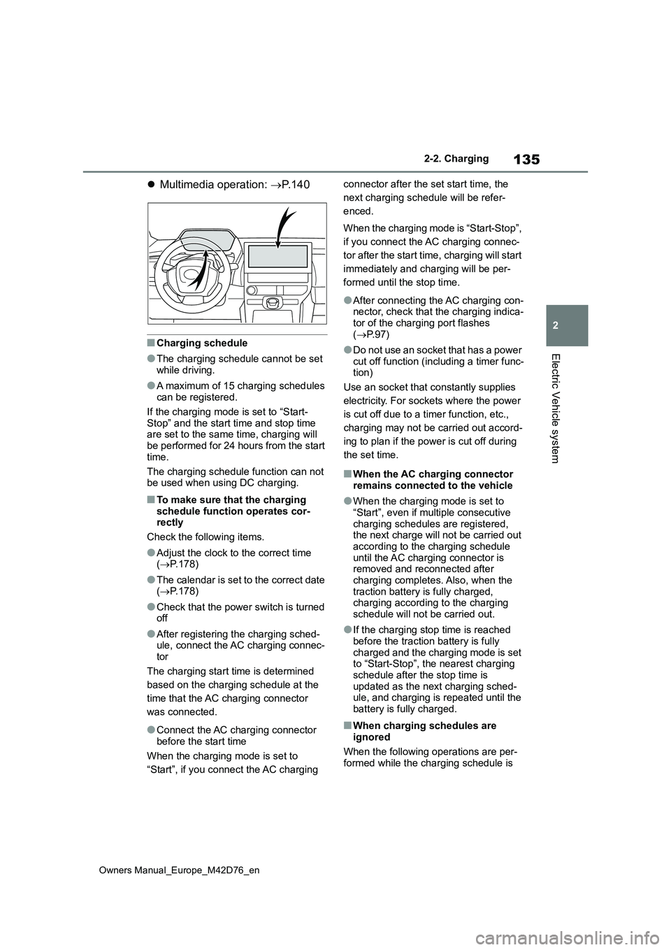
Multimedia operation: P. 1 4 0
■Charging schedule
●The charging schedule cannot be set while driving.
●A maximum of 15 charging schedules can be registered.
If the charging mode is set to “Start-
Stop” and the start time and stop time are set to the same time, charging will be performed for 24 hours from the start
time.
The charging schedule function can not be used when using DC charging.
■To make sure that the charging
schedule function operates cor- rectly
Check the following items.
●Adjust the clock to the correct time ( P.178)
●The calendar is set to the correct date ( P.178)
●Check that the power switch is turned off
●After registering the charging sched-ule, connect the AC charging connec-
tor
The charging start time is determined
based on the charging schedule at the
time that the AC charging connector
was connected.
●Connect the AC charging connector
before the start time
When the charging mode is set to
“Start”, if you connect the AC charging
connector after the set start time, the
next charging schedule will be refer-
enced.
When the charging mode is “Start-Stop”,
if you connect the AC charging connec-
tor after the start time, charging will start
immediately and charging will be per-
formed until the stop time.
●After connecting the AC charging con- nector, check that the charging indica-tor of the charging port flashes
( P. 9 7 )
●Do not use an socket that has a power
cut off function (including a timer func- tion)
Use an socket that constantly supplies
electricity. For sockets where the power
is cut off due to a timer function, etc.,
charging may not be carried out accord-
ing to plan if the power is cut off during
the set time.
■When the AC charging connector remains connected to the vehicle
●When the charging mode is set to “Start”, even if multiple consecutive
charging schedules are registered, the next charge will not be carried out according to the charging schedule
until the AC charging connector is removed and reconnected after charging completes. Also, when the
traction battery is fully charged, charging according to the charging schedule will not be carried out.
●If the charging stop time is reached before the traction battery is fully
charged and the charging mode is set to “Start-Stop”, the nearest charging schedule after the stop time is
updated as the next charging sched- ule, and charging is repeated until the battery is fully charged.
■When charging schedules are
ignored
When the following operations are per- formed while the charging schedule is
Page 146 of 674
144
Owners Manual_Europe_M42D76_en
2-2. Charging
the calendar.
■Turning “Charge now” on
1 Display the “Charging sched-
ule” screen. ( P. 1 4 0 )
2 Press “Charge now”.
Each time the button is pressed,
“Charge now” switches between on
and off.
After setting operations are com-
plete, charging starts when the AC
charging connector is connected.
■Changing Next Event
If the multimedia customize content
“ACC customize” is not set to OFF,
the ending screen will not be dis-
played.If it is this case, check the
settings of the multimedia.
Turn the power switch off.
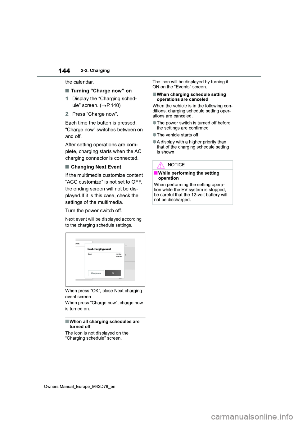
Next event will be displayed according
to the charging schedule settings.
When press “OK”, close Next charging
event screen.
When press “Charge now”, charge now
is turned on.
■When all charging schedules are turned off
The icon is not displayed on the
“Charging schedule” screen.
The icon will be displayed by turning it
ON on the “Events” screen.
■When charging schedule setting operations are canceled
When the vehicle is in the following con-
ditions, charging schedule setting oper- ations are canceled.
●The power switch is turned off before the settings are confirmed
●The vehicle starts off
●A display with a higher priority than
that of the charging schedule setting is shown
NOTICE
■While performing the setting
operation
When performing the setting opera- tion while the EV system is stopped,
be careful that the 12-volt battery will not be discharged.
Page 151 of 674

149
2
Owners Manual_Europe_M42D76_en
2-2. Charging
Electric Vehicle system
Solar roof
Solar ECU
Traction battery
Information related to the solar
charging system can be checked
on the multi-information display and
multimedia.
Meter control switches ( P.176)
Multi-information display
Multimedia
Multi-information display
1 Press or of the meter
control switches to select .
2 Press or of the meter
control switches to select solar
charging screen.
Current power generation
Mileage with power generation*
*: Mileage with power generation from
the end of the previous drive to the
current state. These values are cal-
culated by converting the power gen-
erated into driving distance, and may
differ from the actual driving distance.
When optional tires are installed, the
displayed value may differ from the
actual driving distance.
Multimedia
Energy screen
1 Press .
2 Press “Solar charging”.
If a screen other than the desired one is displayed, select “Energy” on the
Displaying information
related to the solar charging
system
Page 176 of 674
174
Owners Manual_Europe_M42D76_en
3-1. Instrument cluster
●When “--” is displayed, the system
may be malfunctioning. Take your vehicle to any authorized Toyota retailer or Toyota authorized repairer,
or any reliable repairer.
●When the outside temperature is
approximately 3°C (37°F) or lower, the
indicator will flash for approxi-
mately 10 seconds, then stay on.
■Liquid crystal display
P. 1 7 6
■Customization
The gauges and meters can be custom-
ized in of the multi-information dis-
play. ( P.561)
The Multi-Information display can
be switched between display and
hidden.
■Display items
Odometer
Displays the total distance the vehicle
has been driven.
Trip meter A/Trip meter B
Displays the distance the vehicle has
been driven since the meter was last
reset. Trip meters A and B can be used
to record and display different distances
independently.
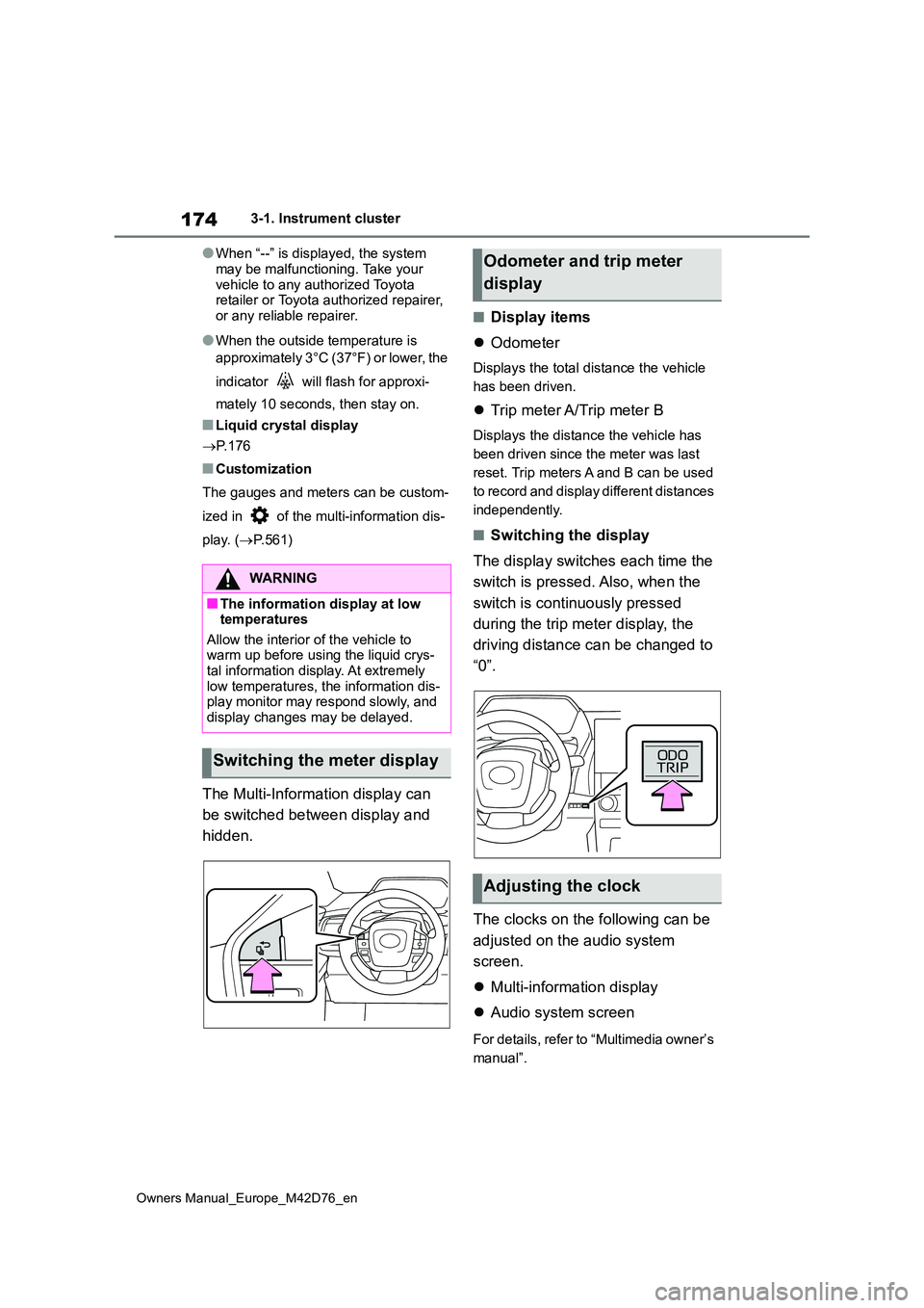
■Switching the display
The display switches each time the
switch is pressed. Also, when the
switch is continuously pressed
during the trip meter display, the
driving distance can be changed to
“0”.
The clocks on the following can be
adjusted on the audio system
screen.
Multi-information display
Audio system screen
For details, refer to “Multimedia owner’s
manual”.
WARNING
■The information display at low temperatures
Allow the interior of the vehicle to warm up before using the liquid crys-tal information display. At extremely
low temperatures, the information dis- play monitor may respond slowly, and display changes may be delayed.
Switching the meter display
Odometer and trip meter
display
Adjusting the clock