warning light TOYOTA BZ4X 2023 Owner's Manual
[x] Cancel search | Manufacturer: TOYOTA, Model Year: 2023, Model line: BZ4X, Model: TOYOTA BZ4X 2023Pages: 628, PDF Size: 11.91 MB
Page 111 of 628
1112-2. Charging
Owners Manual_USA_M42C01_en
2
Electric Vehicle system
1 Unlock the doors to unlock
the charging connector.
( P.93)
The charging connector will be
unlocked and the AC charging inlet
light will illuminate when the doors
are unlocked.
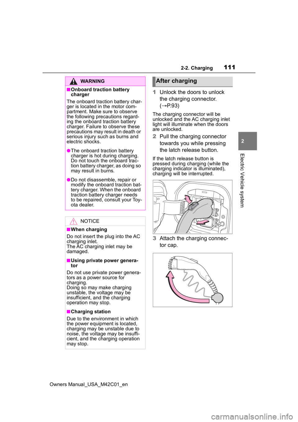
2Pull the charging connector
towards you while pressing
the latch release button.
If the latch release button is
pressed during charging (while the
charging indicator is illuminated),
charging will be interrupted.
3 Attach the charging connec-
tor cap.
WARNING
■Onboard traction battery
charger
The onboard traction battery char-
ger is located in the motor com-
partment. Make sure to observe
the following precautions regard-
ing the onboard traction battery
charger. Failure to observe these
precautions may result in death or
serious injury suc h as burns and
electric shocks.
●The onboard traction battery
charger is hot during charging.
Do not touch the onboard trac-
tion battery charger, as doing so
may result in burns.
●Do not disassemble, repair or
modify the onboard traction bat-
tery charger. When the onboard
traction battery charger needs
to be repaired, consult your Toy-
ota dealer.
NOTICE
■When charging
Do not insert the p lug into the AC
charging inlet.
The AC charging inlet may be
damaged.
■Using private power genera-
tor
Do not use private power genera-
tors as a power source for
charging.
Doing so may make charging
unstable, the voltage may be
insufficient, and the charging
operation may stop.
■Charging station
Due to the environment in which
the power equipme nt is located,
charging may be unstable due to
noise, the voltage may be insuffi-
cient, and the charging operation
may stop.
After charging
Page 112 of 628
1122-2. Charging
Owners Manual_USA_M42C01_en
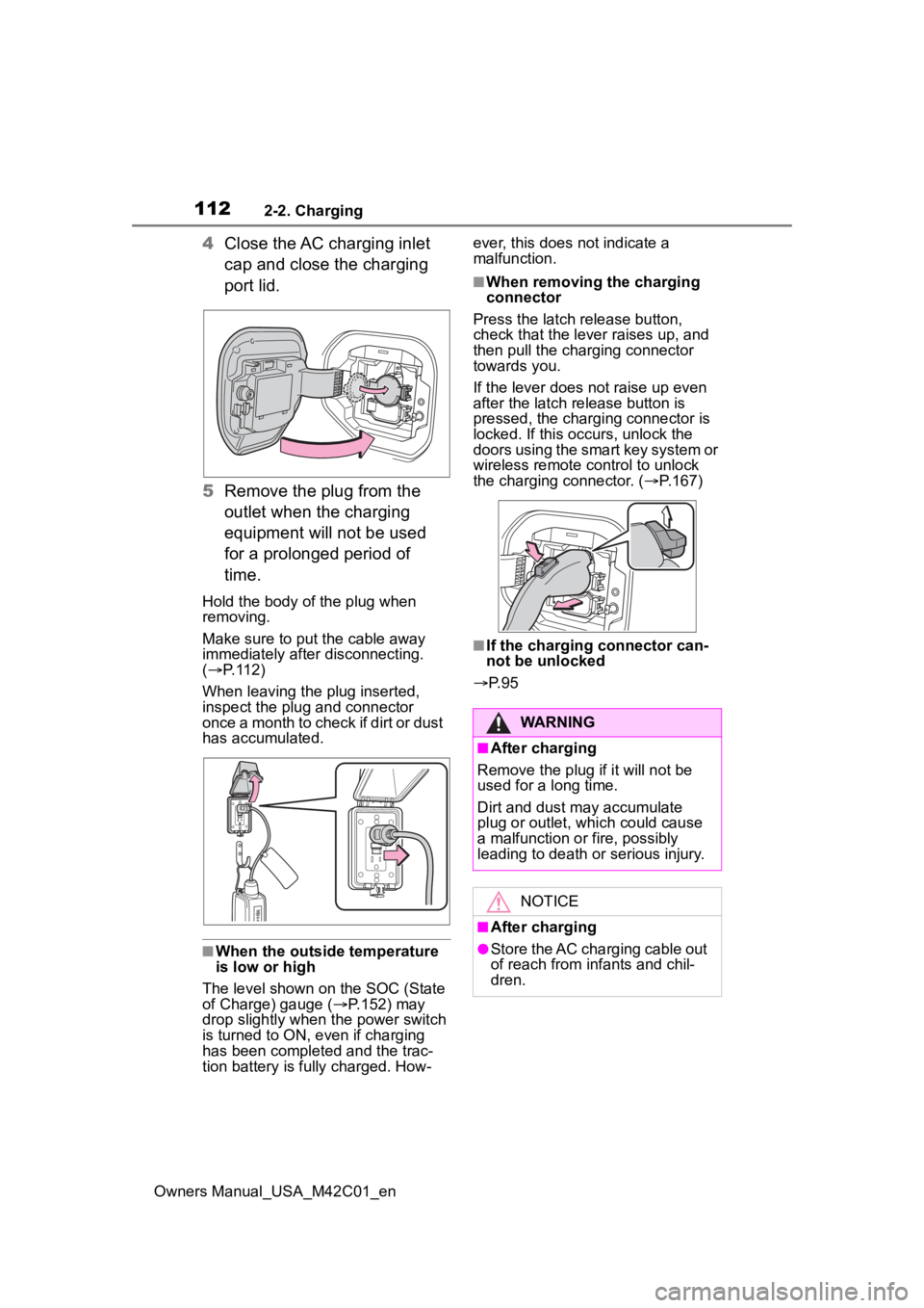
4Close the AC charging inlet
cap and close the charging
port lid.
5 Remove the plug from the
outlet when the charging
equipment will not be used
for a prolonged period of
time.
Hold the body of the plug when
removing.
Make sure to put the cable away
immediately afte r disconnecting.
( P. 1 1 2 )
When leaving the plug inserted,
inspect the plug and connector
once a month to check if dirt or dust
has accumulated.
■When the outside temperature
is low or high
The level shown on the SOC (State
of Charge) gauge ( P.152) may
drop slightly when the power switch
is turned to ON, e ven if charging
has been completed and the trac-
tion battery is fully charged. How- ever, this does not indicate a
malfunction.
■When removing the charging
connector
Press the latch release button,
check that the lever raises up, and
then pull the charging connector
towards you.
If the lever does not raise up even
after the latch release button is
pressed, the charging connector is
locked. If this occurs, unlock the
doors using the smart key system or
wireless remote control to unlock
the charging connector. ( P.167)
■If the charging connector can-
not be unlocked
P. 9 5
WARNING
■After charging
Remove the plug if it will not be
used for a long time.
Dirt and dust may accumulate
plug or outlet, which could cause
a malfunction or fire, possibly
leading to death or serious injury.
NOTICE
■After charging
●Store the AC charging cable out
of reach from infants and chil-
dren.
Page 113 of 628
1132-2. Charging
Owners Manual_USA_M42C01_en
2
Electric Vehicle system
P.102
1 Open the charging port lid.
( P.85)
The charging inlet light will illumi-
NOTICE
●After removing the plug from the
outlet, keep it in a safe place
free from moisture and dust.
The AC charging cable or plug
may be damaged if the cable is
stepped on or ridden over by
the vehicle.
●After disconnecting the charging
connector from the AC charging
inlet, make sure to close the AC
charging inlet cap and close the
charging port lid.
If the AC charging inlet cap is
left open, water or foreign
objects may enter the AC
charging inlet, which could lead
to vehicle damage.
How to use DC
charging
This section explains the
DC charging procedure for
the traction battery.
When using a DC charger,
make sure to check the
operation instructions of
the DC charger.
WARNING
■When using a DC charger
Observe the following precau-
tions.
Failure to do so may cause an
unexpected accident, resulting in
death or serious injury.
●Use a SAE J 1772 compliant
DC charger.
●Do not use the charging cable
longer than 30 meters.
Confirm the following
before charging
When charging
Page 116 of 628
1162-2. Charging
Owners Manual_USA_M42C01_en1
Be sure to engage the parking
brake and then turn the power
switch off.
2 Close the charging inlet cap,
close the charging port lid.
3 Check if “Checking Charging
System” is displayed on the
multi-information display when
the power switch is turned to ON.
Do not open the c harging port lid
while the charging system is check-
ing.
When the system check is com-
pleted, the power switch automati-
cally turns off.
4 Press the power switch while
depressing the brake pedal. The
“READY” indicator turns on.
Contact your Toyot a dealer if the
charging system check is done and
the message on the multi-informa-
tion display does not go off.
WARNING
■Warnings for DC charging
Be sure to observe the following
when using DC charging.
Failure to do so may cause an
accident that could lead to death
or serious injury.
●Check that the DC charger and
DC charging inlet are not dam-
aged. If there is any damage to
the DC charging inlet, do not
perform a DC charge and have
it inspected immediately at your
Toyota dealer.
●Do not touch the terminals of
the DC charging connector or
inlet with metallic sharp tips
(wires and needles), or allow a
short circuit to occur with foreign
objects.
●Do not insert anything other
than the DC charging connector
into the DC charging inlet.
●Check that the DC charging
cable is not coiled up or pinned
underneath heavy objects.
●Be sure the DC charging inlet
makes direct contact with the
DC charging connector.
Do not connect conversion
adapters, extension cords, etc.,
between the DC charging con-
nector and DC ch arging inlet.
●When DC charging is inter-
rupted, follow the handling pro-
cedures of the DC charger.
Immediately stop the DC
charging when the re is an out-
break of heat, smoke, strange
noises or smells, etc., during
charging.
●Check that the DC charging
connector and DC charging inlet
do not have foreign objects or
snow or ice attached to it. If any-
thing is attached t o the inlet, be
sure to complete ly remove the
material before connecting the
DC charging connector.
●Do not charge the vehicle when
there is a possibility of lightning.
If you notice lightning while
charging the vehicle, do not
touch the vehicle and the DC
charging cable.
●Do not get the DC charging inlet
terminals wet.
●Close the hood when using DC
charging. The cooling fan may
suddenly start to run. Keep
hands and clothing (especially a
tie, a scarf or a muffler) away
from the fan. Fa ilure to do so
may cause the hands or cloth-
ing to be caught, resulting in
serious injury.
Page 130 of 628
1302-2. Charging
Owners Manual_USA_M42C01_en
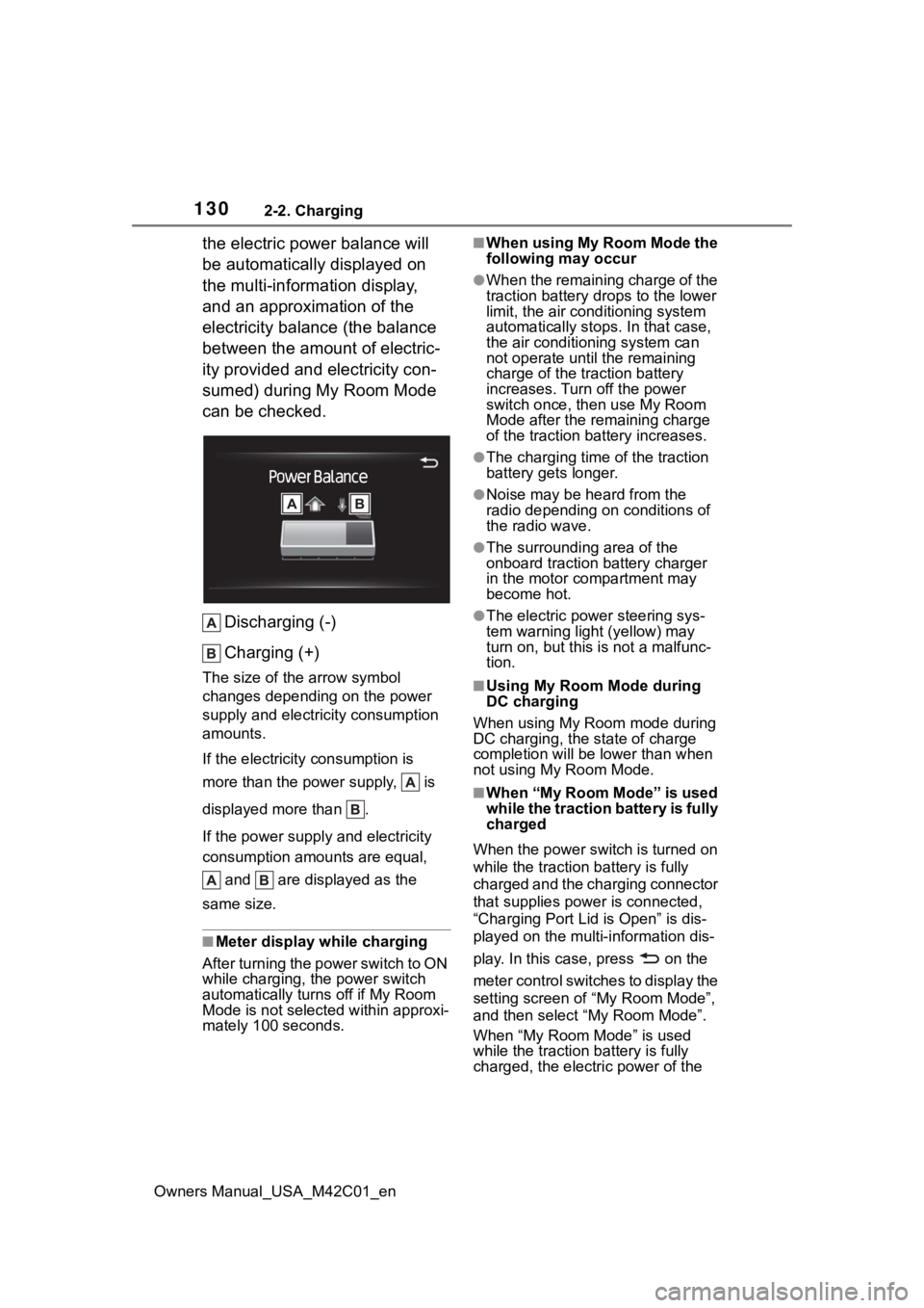
the electric power balance will
be automatically displayed on
the multi-information display,
and an approximation of the
electricity balance (the balance
between the amount of electric-
ity provided and electricity con-
sumed) during My Room Mode
can be checked.Discharging (-)
Charging (+)
The size of the arrow symbol
changes depending on the power
supply and electric ity consumption
amounts.
If the electricity consumption is
more than the power supply, is
displayed more than .
If the power supply and electricity
consumption amounts are equal,
and are displayed as the
same size.
■Meter display while charging
After turning the power switch to ON
while charging, the power switch
automatically turns off if My Room
Mode is not selected within approxi-
mately 100 seconds.
■When using My Room Mode the
following may occur
●When the remaining charge of the
traction battery d rops to the lower
limit, the air conditioning system
automatically stops. In that case,
the air conditioning system can
not operate until the remaining
charge of the traction battery
increases. Turn off the power
switch once, then use My Room
Mode after the remaining charge
of the traction battery increases.
●The charging time of the traction
battery gets longer.
●Noise may be heard from the
radio depending on conditions of
the radio wave.
●The surrounding area of the
onboard traction battery charger
in the motor compartment may
become hot.
●The electric power steering sys-
tem warning light (yellow) may
turn on, but this is not a malfunc-
tion.
■Using My Room Mode during
DC charging
When using My Room mode during
DC charging, the state of charge
completion will be lo wer than when
not using My Room Mode.
■When “My Room Mode” is used
while the traction battery is fully
charged
When the power switch is turned on
while the traction b attery is fully
charged and the charging connector
that supplies power is connected,
“Charging Port Lid is Open” is dis-
played on the multi-information dis-
play. In this cas e, press on the
meter control switches to display the
setting screen of “My Room Mode”,
and then select “My Room Mode”.
When “My Room Mode” is used
while the traction b attery is fully
charged, the electric power of the
Page 147 of 628
147
Owners Manual_USA_M42C01_en
3
3
Vehicle status information and indicators
Vehicle status informa-tion and indicators
3-1. Instrument cluster
Warning lights and indica-tors ............................ 148
Gauges and meters .... 152
Multi-information display .................................. 155
Page 148 of 628
1483-1. Instrument cluster
Owners Manual_USA_M42C01_en
3-1.Instrument cluster
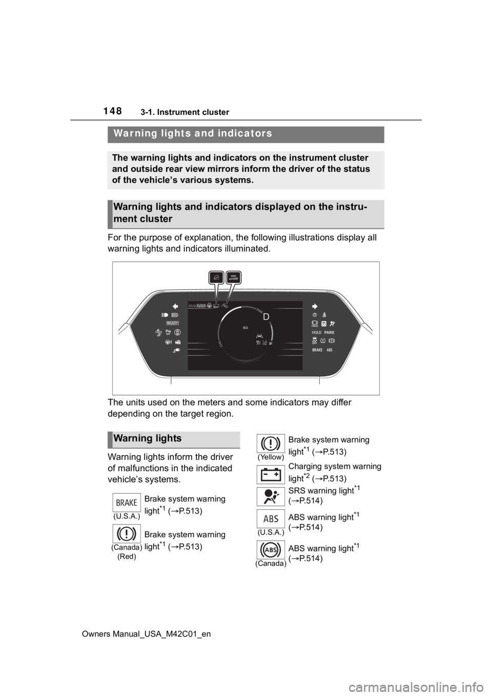
For the purpose of explanation, the following illustrations display all
warning lights and indicators illuminated.
The units used on the meters and some indicators may differ
depending on the target region.
Warning lights inform the driver
of malfunctions in the indicated
vehicle’s systems.
War ning lights and indicators
The warning lights and indicators on the instrument cluster
and outside rear view mirrors inform the driver of the status
of the vehicle’s various systems.
Warning lights and indicators displayed on the instru-
ment cluster
Warning lights
(U.S.A.)
Brake system warning
light
*1 ( P.513)
(Canada)
(Red)
Brake system warning
light
*1 ( P.513)
(Yellow)
Brake system warning
light
*1 ( P.513)
Charging system warning
light
*2 ( P.513)
SRS warning light
*1
( P.514)
(U.S.A.)
ABS warning light*1
( P.514)
(Canada)
ABS warning light*1
( P.514)
Page 149 of 628
1493-1. Instrument cluster
Owners Manual_USA_M42C01_en
3
Vehicle status information and indicators
*1: These lights come on when the power switch is turned to ON to
indicate that a system check is
being performed. They will turn
off after the EV system is started,
or after a few seconds. There
may be a malfunction in a sys-
tem if the lights do not come on,
or turn off. Have the vehicle
inspected by your Toyota dealer.
*2: This light illuminates on the multi-information display with a
message.
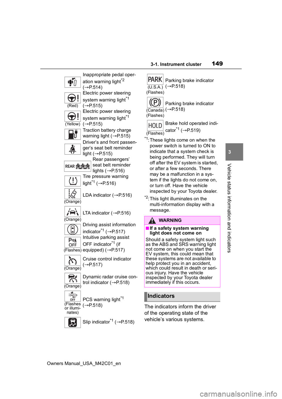
The indicators inform the driver
of the operating state of the
vehicle’s various systems.
Inappropriate pedal oper-
ation warning light
*2
( P.514)
(Red)
Electric power steering
system warning light
*1
( P.515)
(Yellow)
Electric power steering
system warning light
*1
( P.515)
Traction battery charge
warning light ( P.515)
Driver’s and front passen-
ger’s seat belt reminder
light ( P.515)
Rear passengers’
seat belt reminder
lights ( P.516)
Tire pressure warning
light
*1 ( P.516)
(Orange)
LDA indicator ( P.516)
(Orange)
LTA indicator (P.516)
Driving assist information
indicator
*1 ( P.517)
(Flashes)
Intuitive parking assist
OFF indicator
*1 (if
equipped) ( P.517)
(Orange)
Cruise control indicator
( P.517)
(Orange)
Dynamic radar cruise con-
trol indicator ( P.518)
(Flashes
or illumi- nates)PCS warning light*1
( P.518)
Slip indicator
*1 ( P.518)
(U.S.A.)
(Flashes)
Parking brake indicator
( P.518)
(Canada)
(Flashes)
Parking brake indicator
( P.518)
(Flashes)
Brake hold operated indi-
cator
*1 ( P.519)
WARNING
■If a safety system warning
light does not come on
Should a safety system light such
as the ABS and SRS warning light
not come on when you start the
EV system, this c ould mean that
these systems are not available to
help protect you in an accident,
which could result in death or seri-
ous injury. Have the vehicle
inspected by you r Toyota dealer
immediately if this occurs.
Indicators
Page 150 of 628
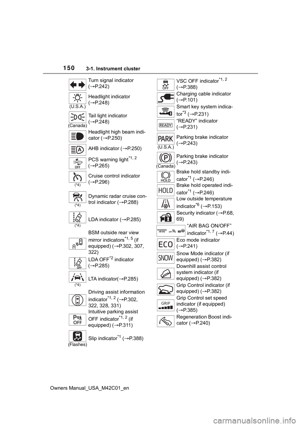
1503-1. Instrument cluster
Owners Manual_USA_M42C01_enTurn signal indicator
(
P.242)
(U.S.A.)
Headlight indicator
( P.248)
(Canada)
Tail light indicator
( P.248)
Headlight high beam indi-
cator ( P.250)
AHB indicator ( P.250)
PCS warning light
*1, 2
( P.265)
(*4)
Cruise control indicator
( P.296)
(*4)
Dynamic radar cruise con-
trol indicator ( P.288)
(*4)
LDA indicator ( P.285)
BSM outside rear view
mirror indicators
*1, 5 (if
equipped) ( P.302, 307,
322)
LDA OFF
*2 indicator
( P.285)
(*4)
LTA i n d i c a t o r ( P.285)
Driving assist information
indicator
*1, 2 ( P.302,
322, 328, 331)
Intuitive parking assist
OFF indicator
*1, 2 (if
equipped) ( P.311)
(Flashes)
Slip indicator*1 ( P.388)
VSC OFF indicator*1, 2
( P.388)
Charging cable indicator
( P.101)
Smart key system indica-
tor
*3 ( P.231)
“READY” indicator
( P.231)
(U.S.A.)
Parking brake indicator
( P.243)
(Canada)
Parking brake indicator
( P.243)
Brake hold standby indi-
cator
*1 ( P.246)
Brake hold operated indi-
cator
*1 ( P.246)
Low outside temperature
indicator
*6 ( P.153)
Security indicator ( P. 6 8 ,
69)
“AIR BAG ON/OFF”
indicator
*1, 7 ( P. 4 4 )
Eco mode indicator
( P.241)
Snow Mode indicator (if
equipped) ( P.382)
Downhill assist control
system indicator (if
equipped) ( P.382)
Grip Control indicator (if
equipped) ( P.382)
Grip Control set speed
indicator (if equipped)
( P.385)
Regeneration Boost indi-
cator ( P.240)
Page 155 of 628
1553-1. Instrument cluster
Owners Manual_USA_M42C01_en
3
Vehicle status information and indicators
If is displayed when is
selected on the mu lti-information
display, the system may be malfunc-
tioning.
Have the vehicle inspected by your
Toyota dealer.
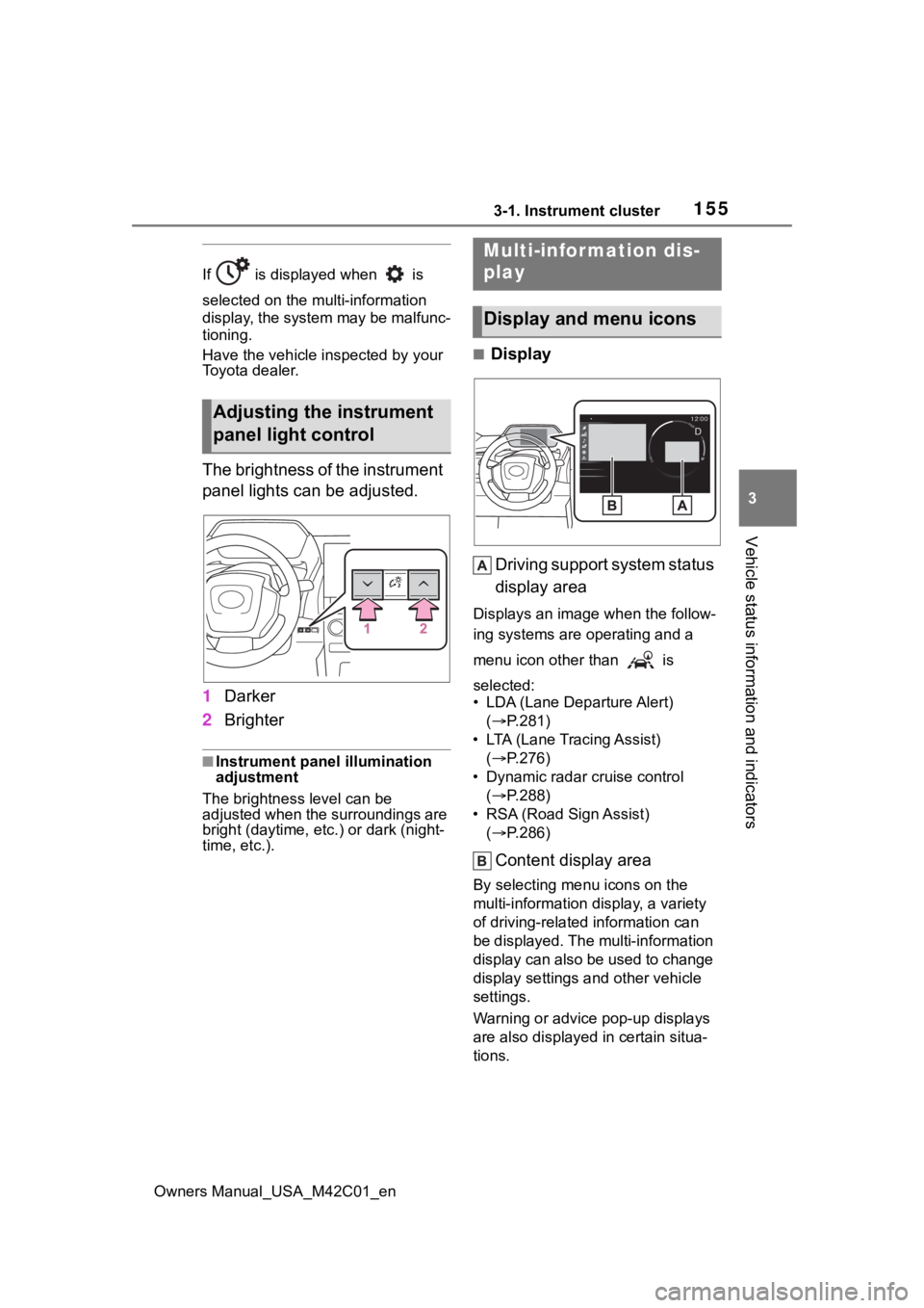
The brightness of the instrument
panel lights can be adjusted.
1 Darker
2 Brighter
■Instrument panel illumination
adjustment
The brightness level can be
adjusted when the surroundings are
bright (daytime, etc.) or dark (night-
time, etc.).
■Display
Driving support system status
display area
Displays an image when the follow-
ing systems are operating and a
menu icon other than is
selected:
• LDA (Lane Departure Alert) ( P.281)
• LTA (Lane Tracing Assist) ( P.276)
• Dynamic radar cruise control ( P.288)
• RSA (Road Sign Assist) ( P.286)
Content display area
By selecting menu icons on the
multi-information di splay, a variety
of driving-related information can
be displayed. The multi-information
display can also be used to change
display settings and other vehicle
settings.
Warning or advice pop-up displays
are also displayed in certain situa-
tions.
Adjusting the instrument
panel light control
Multi-infor mation dis-
play
Display and menu icons