TOYOTA CAMRY V20 1986 Service Information
CAMRY V20 1986
TOYOTA
TOYOTA
https://www.carmanualsonline.info/img/14/57449/w960_57449-0.png
TOYOTA CAMRY V20 1986 Service Information
Trending: torque, wipers, suspension, clutch, tire size, check engine light, emergency towing
Page 621 of 2389
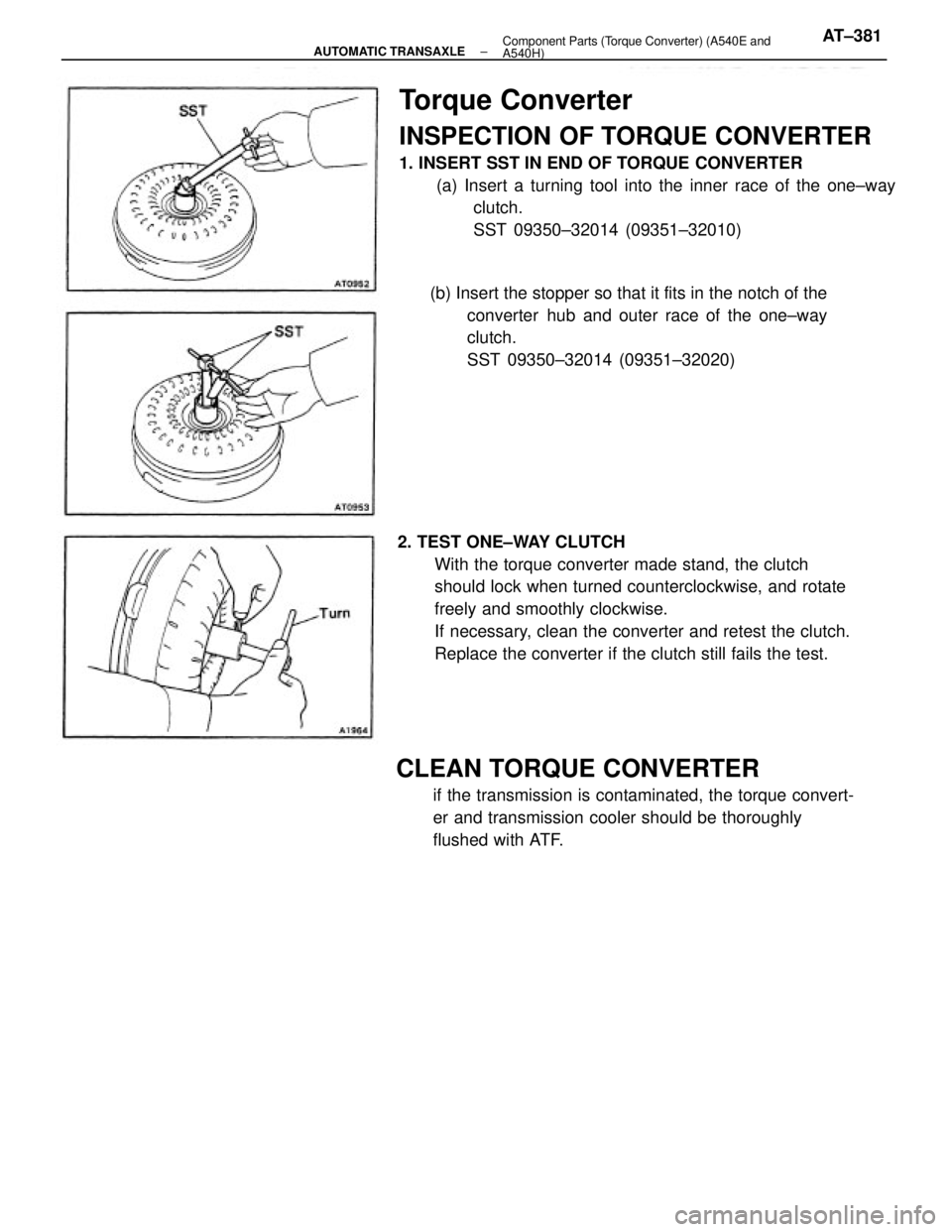
Torque Converter
INSPECTION OF TORQUE CONVERTER
1. INSERT SST IN END OF TORQUE CONVERTER
(a) Insert a turning tool into the inner race of the one±way
clutch.
SST 09350±32014 (09351±32010)
2. TEST ONE±WAY CLUTCH
With the torque converter made stand, the clutch
should lock when turned counterclockwise, and rotate
freely and smoothly clockwise.
If necessary, clean the converter and retest the clutch.
Replace the converter if the clutch still fails the test.
CLEAN TORQUE CONVERTER
if the transmission is contaminated, the torque convert-
er and transmission cooler should be thoroughly
flushed with ATF. (b) Insert the stopper so that it fits in the notch of the
converter hub and outer race of the one±way
clutch.
SST 09350±32014 (09351±32020)
± AUTOMATIC TRANSAXLEComponent Parts (Torque Converter) (A540E and
A540H)AT±381
Page 622 of 2389
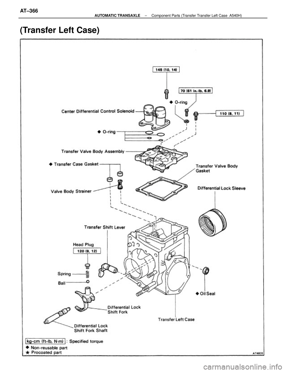
(Transfer Left Case)
± AUTOMATIC TRANSAXLEComponent Parts (Transfer Transfer Left Case A540H)AT±366
Page 623 of 2389
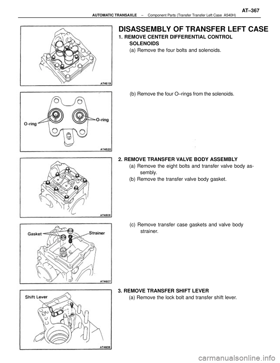
2. REMOVE TRANSFER VALVE BODY ASSEMBLY
(a) Remove the eight bolts and transfer valve body as-
sembly.
(b) Remove the transfer valve body gasket.
DISASSEMBLY OF TRANSFER LEFT CASE
1. REMOVE CENTER DIFFERENTIAL CONTROL
SOLENOIDS
(a) Remove the four bolts and solenoids.
3. REMOVE TRANSFER SHIFT LEVER
(a) Remove the lock bolt and transfer shift lever.(c) Remove transfer case gaskets and valve body
strainer. (b) Remove the four O±rings from the solenoids.
± AUTOMATIC TRANSAXLEComponent Parts (Transfer Transfer Left Case A540H)AT±367
Page 624 of 2389
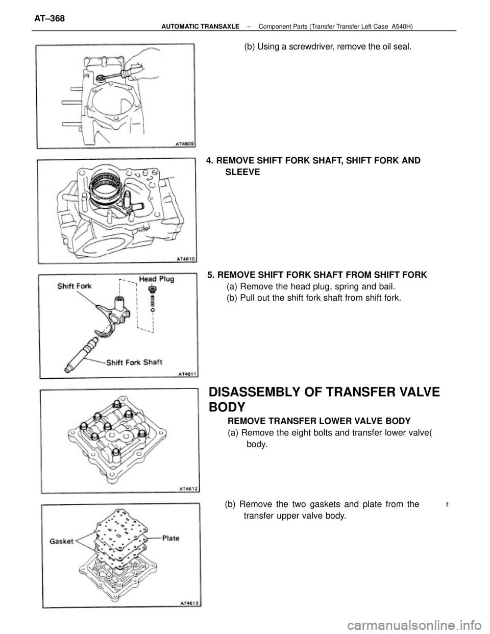
DISASSEMBLY OF TRANSFER VALVE
BODY
REMOVE TRANSFER LOWER VALVE BODY
(a) Remove the eight bolts and transfer lower valve(
body. 5. REMOVE SHIFT FORK SHAFT FROM SHIFT FORK
(a) Remove the head plug, spring and bail.
(b) Pull out the shift fork shaft from shift fork.
(b) Remove the two gaskets and plate from the
transfer upper valve body. 4. REMOVE SHIFT FORK SHAFT, SHIFT FORK AND
SLEEVE(b) Using a screwdriver, remove the oil seal.
± AUTOMATIC TRANSAXLEComponent Parts (Transfer Transfer Left Case A540H)AT±368
Page 625 of 2389
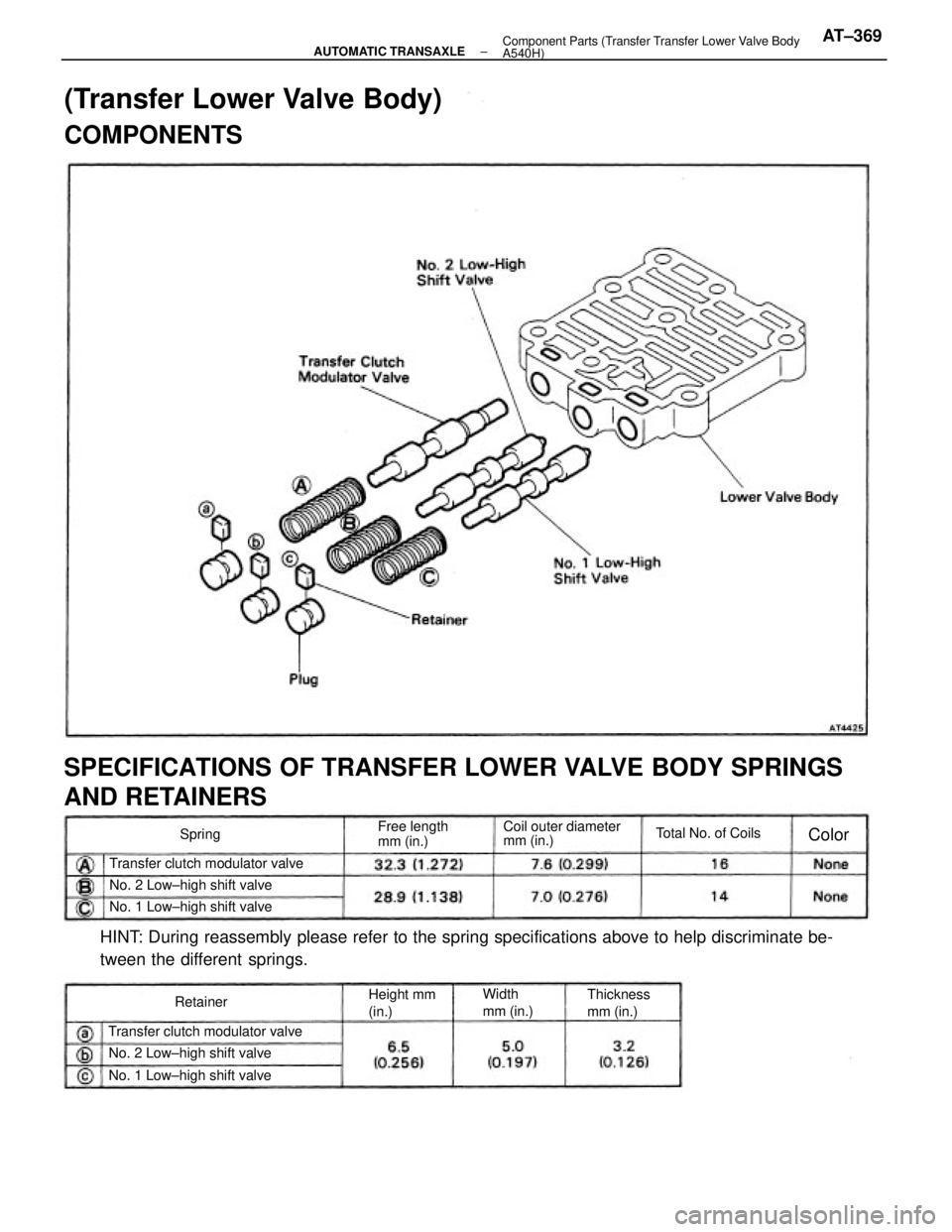
HINT: During reassembly please refer to the spring specifications above to help discriminate be-
tween the different springs.
SPECIFICATIONS OF TRANSFER LOWER VALVE BODY SPRINGS
AND RETAINERS
(Transfer Lower Valve Body)
COMPONENTS
Transfer clutch modulator valveTransfer clutch modulator valveCoil outer diameter
mm (in.)
No. 2 Low±high shift valveNo. 2 Low±high shift valve
No. 1 Low±high shift valveNo. 1 Low±high shift valveFree length
mm (in.)Total No. of Coils
Thickness
mm (in.) Height mm
(in.)Width
mm (in.) RetainerSpring
Color
± AUTOMATIC TRANSAXLEComponent Parts (Transfer Transfer Lower Valve Body
A540H)AT±369
Page 626 of 2389
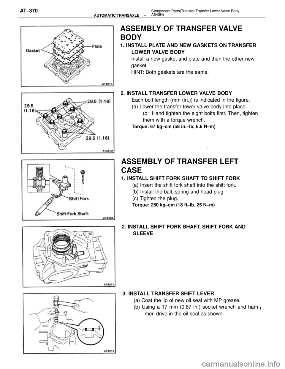
ASSEMBLY OF TRANSFER VALVE
BODY
1. INSTALL PLATE AND NEW GASKETS ON TRANSFER
LOWER VALVE BODY
Install a new gasket and plate and then the other new
gasket.
HINT: Both gaskets are the same.
2. INSTALL TRANSFER LOWER VALVE BODY
Each bolt length (mm (in.)) is indicated in the figure.
(a) Lower the transfer tower valve body into place.
(b1 Hand tighten the eight bolts first. Then, tighten
them with a torque wrench.
Torque: 67 kg±cm (58 in.±lb, 6.6 N±m)
ASSEMBLY OF TRANSFER LEFT
CASE
1. INSTALL SHIFT FORK SHAFT TO SHIFT FORK
(a) Insert the shift fork shaft into the shift fork.
(b) Install the ball, spring and head plug.
(c) Tighten the plug.
Torque: 250 kg±cm (18 ft±Ib, 25 N±m)
3. INSTALL TRANSFER SHIFT LEVER
(a) Coat the lip of new oil seal with MP grease.
(b) Using a 17 mm (0.67 in.) socket wrench and ham
mer, drive in the oil seal as shown. 2. INSTALL SHIFT FORK SHAFT, SHIFT FORK AND
SLEEVE
± AUTOMATIC TRANSAXLEComponent Parts(Transfer Transfer Lower Valve Body
A540H)AT±370
Page 627 of 2389
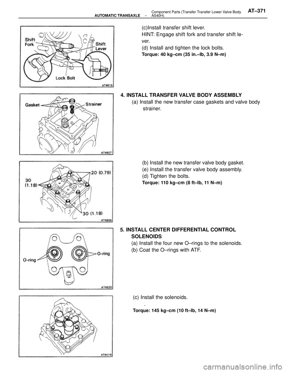
5. INSTALL CENTER DIFFERENTIAL CONTROL
SOLENOIDS
(a) Install the four new O±rings to the solenoids.
(b) Coat the O±rings with ATF.(c)Install transfer shift lever.
HINT: Engage shift fork and transfer shift le-
ver.
(d) Install and tighten the lock bolts.
Torque: 40 kg±cm (35 in.±Ib, 3.9 N±m)
(b) Install the new transfer valve body gasket.
(e) Install the transfer valve body assembly.
(d) Tighten the bolts.
Torque: 110 kg±cm (8 ft±lb, 11 N±m)
4. INSTALL TRANSFER VALVE BODY ASSEMBLY
(a) Install the new transfer case gaskets and valve body
strainer.
(c) Install the solenoids.
.
Torque: 145 kg±cm (10 ft±Ib, 14 N±m)
± AUTOMATIC TRANSAXLEComponent Parts (Transfer Transfer Lower Valve Body
A540H)AT±371
Page 628 of 2389
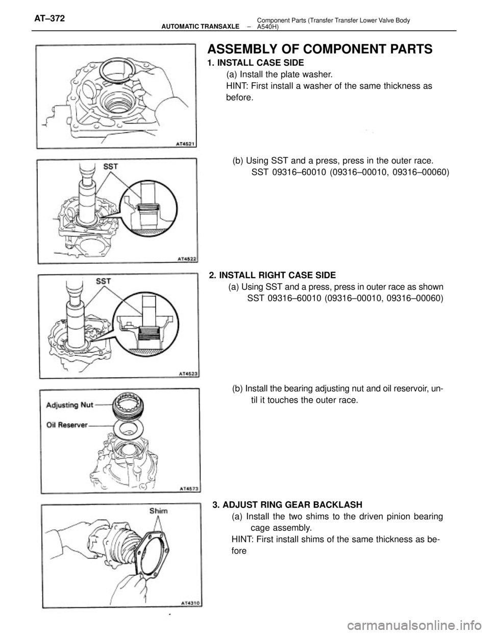
ASSEMBLY OF COMPONENT PARTS
1. INSTALL CASE SIDE
(a) Install the plate washer.
HINT: First install a washer of the same thickness as
before.
3. ADJUST RING GEAR BACKLASH
(a) Install the two shims to the driven pinion bearing
cage assembly.
HINT: First install shims of the same thickness as be-
fore 2. INSTALL RIGHT CASE SIDE
(a) Using SST and a press, press in outer race as shown
SST 09316±60010 (09316±00010, 09316±00060)
(b) Install the bearing adjusting nut and oil reservoir, un-
til it touches the outer race. (b) Using SST and a press, press in the outer race.
SST 09316±60010 (09316±00010, 09316±00060)
± AUTOMATIC TRANSAXLEComponent Parts (Transfer Transfer Lower Valve Body
A540H)AT±372
Page 629 of 2389
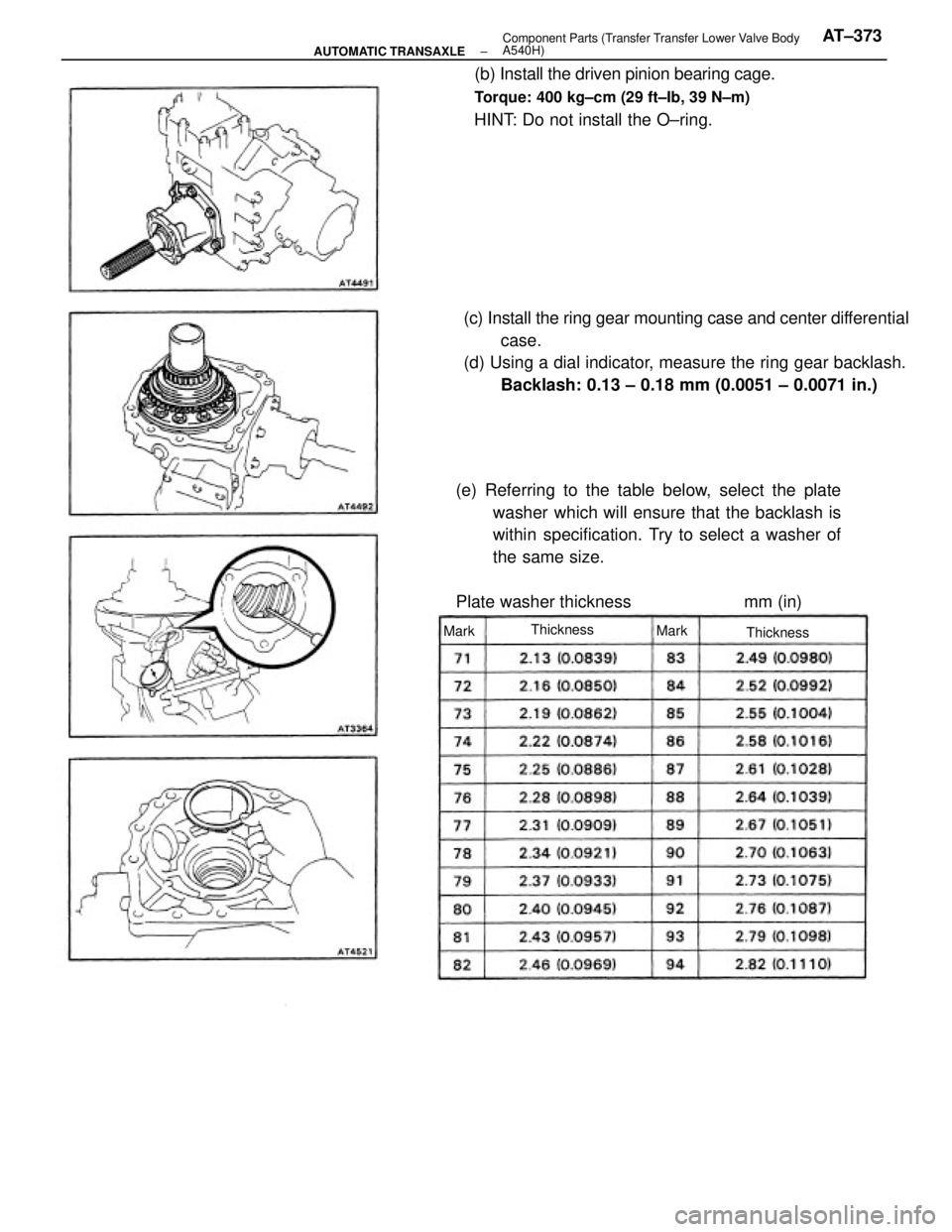
(c) Install the ring gear mounting case and center differential
case.
(d) Using a dial indicator, measure the ring gear backlash.
Backlash: 0.13 ± 0.18 mm (0.0051 ± 0.0071 in.)
(e) Referring to the table below, select the plate
washer which will ensure that the backlash is
within specification. Try to select a washer of
the same size.
Plate washer thickness mm (in)(b) Install the driven pinion bearing cage.
Torque: 400 kg±cm (29 ft±Ib, 39 N±m)
HINT: Do not install the O±ring.
Thickness
Thickness Mark
Mark
± AUTOMATIC TRANSAXLEComponent Parts (Transfer Transfer Lower Valve Body
A540H)AT±373
Page 630 of 2389
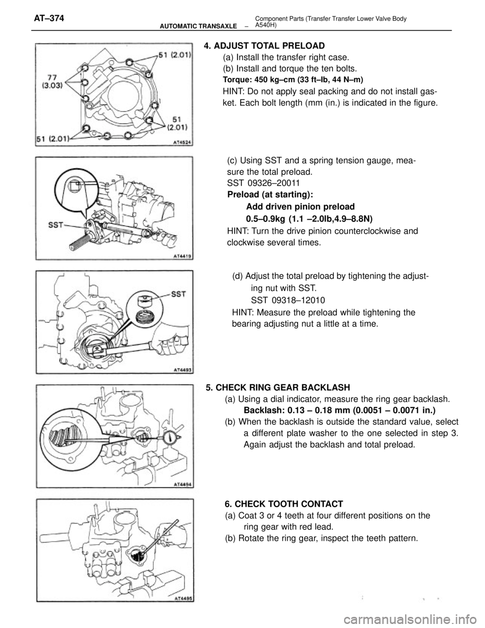
4. ADJUST TOTAL PRELOAD
(a) Install the transfer right case.
(b) Install and torque the ten bolts.
Torque: 450 kg±cm (33 ft±Ib, 44 N±m)
HINT: Do not apply seal packing and do not install gas-
ket. Each bolt length (mm (in.) is indicated in the figure.
(c) Using SST and a spring tension gauge, mea-
sure the total preload.
SST 09326±20011
Preload (at starting):
Add driven pinion preload
0.5±0.9kg (1.1 ±2.0lb,4.9±8.8N)
HINT: Turn the drive pinion counterclockwise and
clockwise several times.
5. CHECK RING GEAR BACKLASH
(a) Using a dial indicator, measure the ring gear backlash.
Backlash: 0.13 ± 0.18 mm (0.0051 ± 0.0071 in.)
(b) When the backlash is outside the standard value, select
a different plate washer to the one selected in step 3.
Again adjust the backlash and total preload. (d) Adjust the total preload by tightening the adjust-
ing nut with SST.
SST 09318±12010
HINT: Measure the preload while tightening the
bearing adjusting nut a little at a time.
6. CHECK TOOTH CONTACT
(a) Coat 3 or 4 teeth at four different positions on the
ring gear with red lead.
(b) Rotate the ring gear, inspect the teeth pattern.
± AUTOMATIC TRANSAXLEComponent Parts (Transfer Transfer Lower Valve Body
A540H)AT±374
Trending: air condition, ECU, gas mileage, heating, battery capacity, brake sensor, air bleeding
