TOYOTA CAMRY V20 1986 Service Information
CAMRY V20 1986
TOYOTA
TOYOTA
https://www.carmanualsonline.info/img/14/57449/w960_57449-0.png
TOYOTA CAMRY V20 1986 Service Information
Trending: reset, radiator, service interval, wheel torque, transmission fluid, roof rack, wiper fluid
Page 661 of 2389
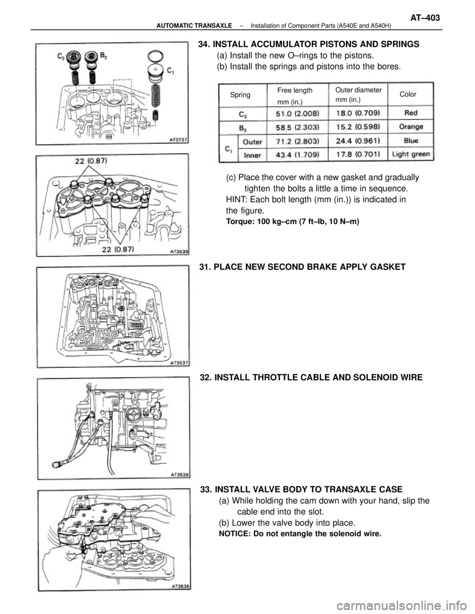
33. INSTALL VALVE BODY TO TRANSAXLE CASE
(a) While holding the cam down with your hand, slip the
cable end into the slot.
(b) Lower the valve body into place.
NOTICE: Do not entangle the solenoid wire.
(c) Place the cover with a new gasket and gradually
tighten the bolts a little a time in sequence.
HINT: Each bolt length (mm (in.)) is indicated in
the figure.
Torque: 100 kg±cm (7 ft±Ib, 10 N±m)
34. INSTALL ACCUMULATOR PISTONS AND SPRINGS
(a) Install the new O±rings to the pistons.
(b) Install the springs and pistons into the bores.
31. PLACE NEW SECOND BRAKE APPLY GASKET
32. INSTALL THROTTLE CABLE AND SOLENOID WIRE
Outer diameter
mm (in.) Free length
mm (in.) SpringColor
± AUTOMATIC TRANSAXLEInstallation of Component Parts (A540E and A540H)AT±403
Page 662 of 2389
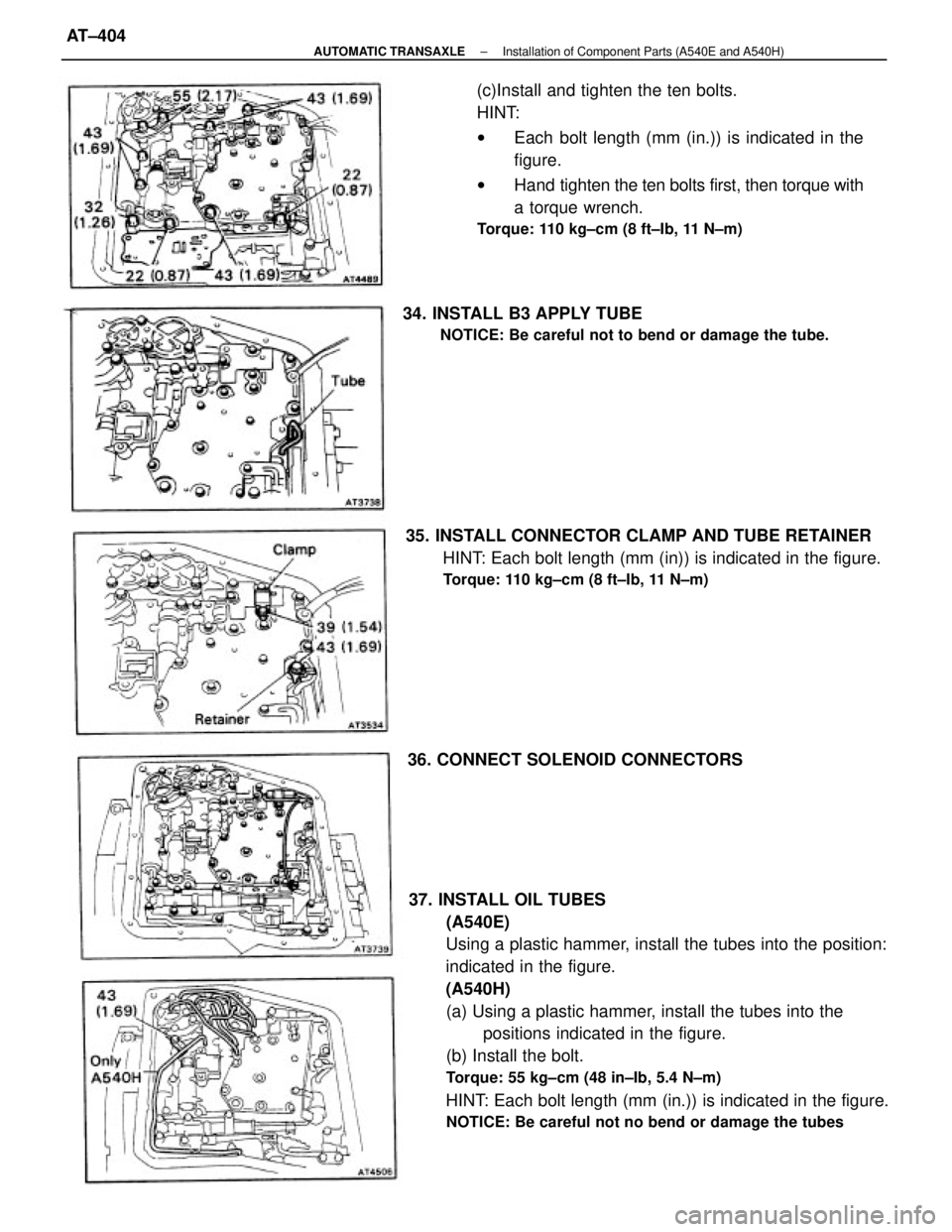
37. INSTALL OIL TUBES
(A540E)
Using a plastic hammer, install the tubes into the position:
indicated in the figure.
(A540H)
(a) Using a plastic hammer, install the tubes into the
positions indicated in the figure.
(b) Install the bolt.
Torque: 55 kg±cm (48 in±Ib, 5.4 N±m)
HINT: Each bolt length (mm (in.)) is indicated in the figure.
NOTICE: Be careful not no bend or damage the tubes
(c)Install and tighten the ten bolts.
HINT:
wEach bolt length (mm (in.)) is indicated in the
figure.
wHand tighten the ten bolts first, then torque with
a torque wrench.
Torque: 110 kg±cm (8 ft±Ib, 11 N±m)
35. INSTALL CONNECTOR CLAMP AND TUBE RETAINER
HINT: Each bolt length (mm (in)) is indicated in the figure.
Torque: 110 kg±cm (8 ft±Ib, 11 N±m)
34. INSTALL B3 APPLY TUBE
NOTICE: Be careful not to bend or damage the tube.
36. CONNECT SOLENOID CONNECTORS
± AUTOMATIC TRANSAXLEInstallation of Component Parts (A540E and A540H)AT±404
Page 663 of 2389

38. INSTALL MANUAL VALVE BODY AND DETENT
SPRING
HINT: Each bolt length (mm (in.)) is indicated in the figure.
(a) Align the manual valve with the pin on the manual shaft le-
ver.
(b) Lower the manual valve body into place.
(e¿ Hand tighten the five bolts first. Then, tighten them
with a torque wrench.
Torque: 110 kg±cm (8 ft±Ib, 11 N±m)
(d) Place the detent springs on the manual valve body and
hand tighten the two bolts first.
Then, tighten them with a torque±wrench.
Torque: 110 kg±cm (8 ft±Ib, 11 N±m)
HINT: Each bolt length (mm (in.)) is indicated in the figure.
(e) Check that the manual valve lever is touching the center of
the detent spring tip roller.
39. INSTALL TUBE BRACKET AND OIL STRAINER
Each bolt length (mm (in.)) is indicated in the figure.
Torque:
Tube bracket 100 kg±cm (7 ft±Ib, 10 N±m)
Oil strainer 110 kg±cm (8 ft±Ib, 11 N±m))
40. INSTALL MAGNETS IN PLACE AS SHOWN
NOTICE: Make sure that the magnets do not interfere with
the oil tubes.
41. INSTALL OIL PAN WITH NEW GASKET
Torque: 50 kg±cm (43 in±Ib, 4.9 N±m)
± AUTOMATIC TRANSAXLEInstallation of Component Parts (A540E and A540H)AT±405
Page 664 of 2389
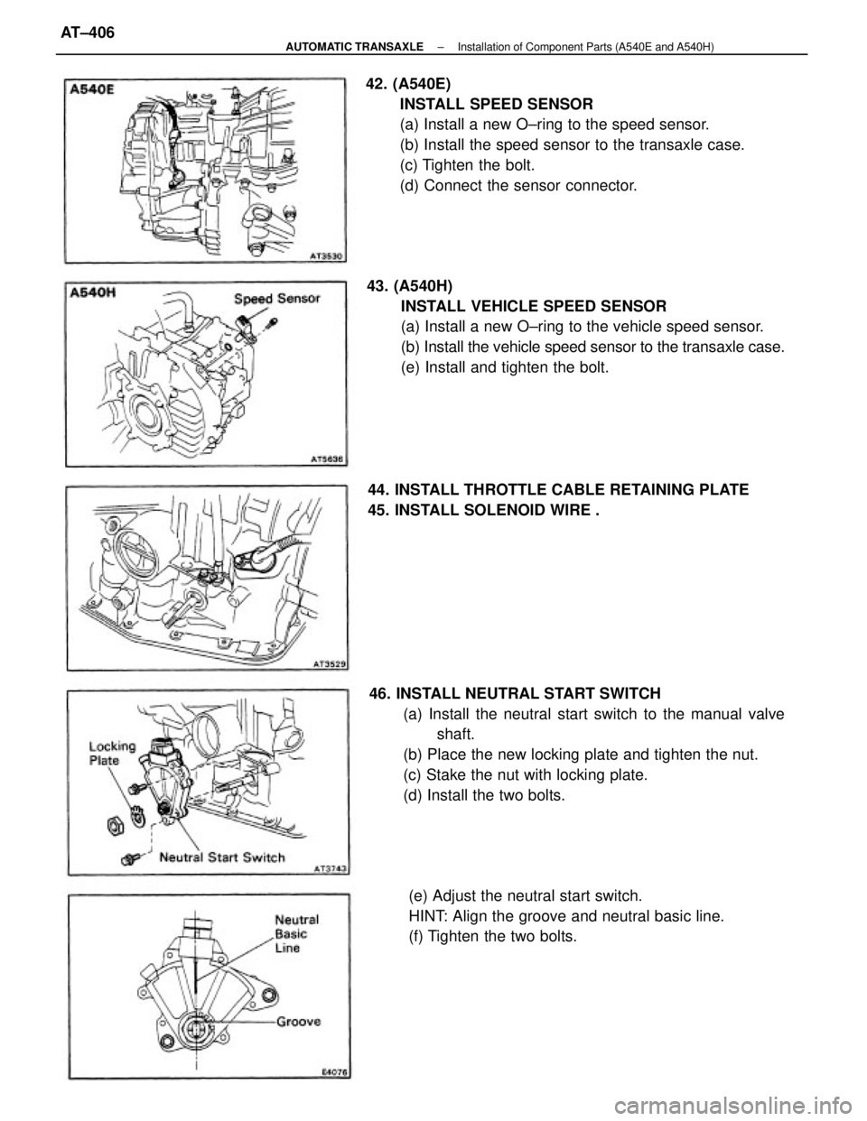
46. INSTALL NEUTRAL START SWITCH
(a) Install the neutral start switch to the manual valve
shaft.
(b) Place the new locking plate and tighten the nut.
(c) Stake the nut with locking plate.
(d) Install the two bolts. 42. (A540E)
INSTALL SPEED SENSOR
(a) Install a new O±ring to the speed sensor.
(b) Install the speed sensor to the transaxle case.
(c) Tighten the bolt.
(d) Connect the sensor connector.
43. (A540H)
INSTALL VEHICLE SPEED SENSOR
(a) Install a new O±ring to the vehicle speed sensor.
(b) Install the vehicle speed sensor to the transaxle case.
(e) Install and tighten the bolt.
(e) Adjust the neutral start switch.
HINT: Align the groove and neutral basic line.
(f) Tighten the two bolts. 44. INSTALL THROTTLE CABLE RETAINING PLATE
45. INSTALL SOLENOID WIRE .
± AUTOMATIC TRANSAXLEInstallation of Component Parts (A540E and A540H)AT±406
Page 665 of 2389
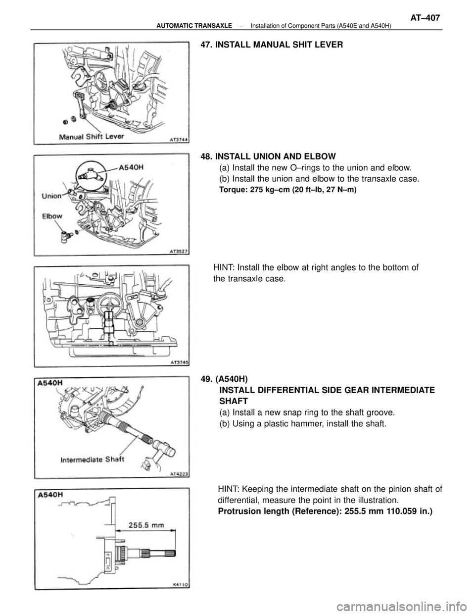
49. (A540H)
INSTALL DIFFERENTIAL SIDE GEAR INTERMEDIATE
SHAFT
(a) Install a new snap ring to the shaft groove.
(b) Using a plastic hammer, install the shaft. 48. INSTALL UNION AND ELBOW
(a) Install the new O±rings to the union and elbow.
(b) Install the union and elbow to the transaxle case.
Torque: 275 kg±cm (20 ft±Ib, 27 N±m)
HINT: Keeping the intermediate shaft on the pinion shaft of
differential, measure the point in the illustration.
Protrusion length (Reference): 255.5 mm 110.059 in.) HINT: Install the elbow at right angles to the bottom of
the transaxle case. 47. INSTALL MANUAL SHIT LEVER
± AUTOMATIC TRANSAXLEInstallation of Component Parts (A540E and A540H)AT±407
Page 666 of 2389
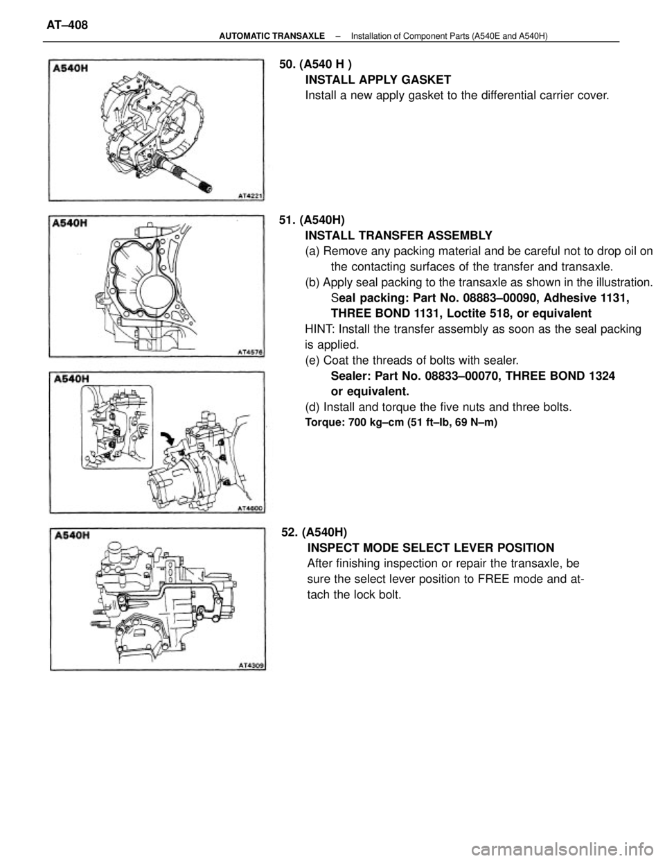
51. (A540H)
INSTALL TRANSFER ASSEMBLY
(a) Remove any packing material and be careful not to drop oil on
the contacting surfaces of the transfer and transaxle.
(b) Apply seal packing to the transaxle as shown in the illustration.
Seal packing: Part No. 08883±00090, Adhesive 1131,
THREE BOND 1131, Loctite 518, or equivalent
HINT: Install the transfer assembly as soon as the seal packing
is applied.
(e) Coat the threads of bolts with sealer.
Sealer: Part No. 08833±00070, THREE BOND 1324
or equivalent.
(d) Install and torque the five nuts and three bolts.
Torque: 700 kg±cm (51 ft±Ib, 69 N±m)
52. (A540H)
INSPECT MODE SELECT LEVER POSITION
After finishing inspection or repair the transaxle, be
sure the select lever position to FREE mode and at-
tach the lock bolt. 50. (A540 H )
INSTALL APPLY GASKET
Install a new apply gasket to the differential carrier cover.
± AUTOMATIC TRANSAXLEInstallation of Component Parts (A540E and A540H)AT±408
Page 667 of 2389
Page 668 of 2389
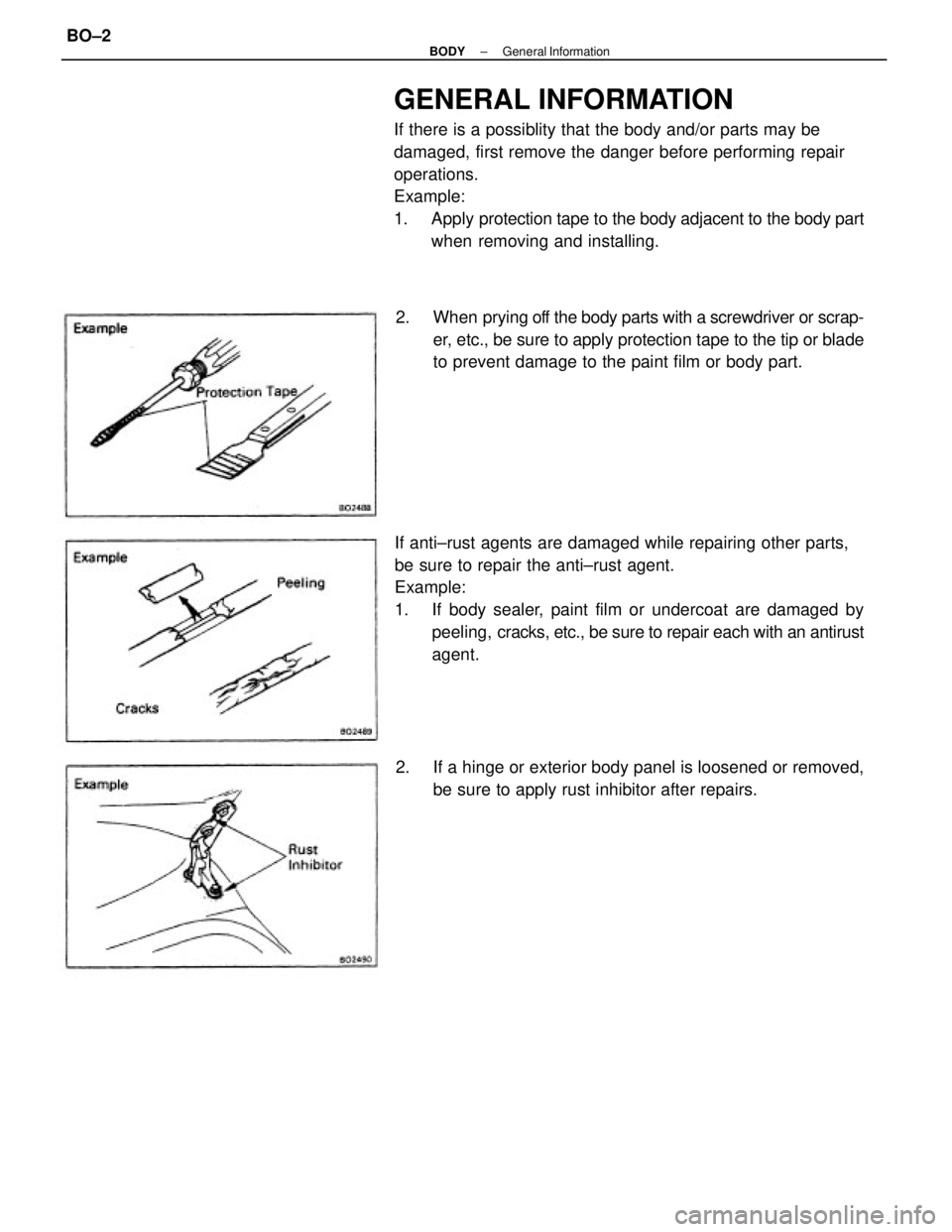
GENERAL INFORMATION
If there is a possiblity that the body and/or parts may be
damaged, first remove the danger before performing repair
operations.
Example:
1. Apply protection tape to the body adjacent to the body part
when removing and installing.
If anti±rust agents are damaged while repairing other parts,
be sure to repair the anti±rust agent.
Example:
1. If body sealer, paint film or undercoat are damaged by
peeling, cracks, etc., be sure to repair each with an antirust
agent. 2. When prying off the body parts with a screwdriver or scrap-
er, etc., be sure to apply protection tape to the tip or blade
to prevent damage to the paint film or body part.
2. If a hinge or exterior body panel is loosened or removed,
be sure to apply rust inhibitor after repairs.
± BODYGeneral InformationBO±2
Page 669 of 2389
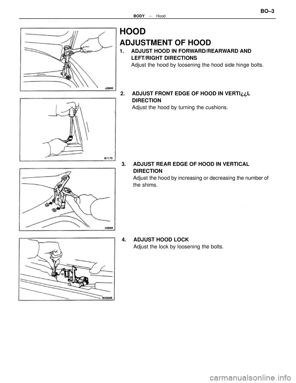
HOOD
ADJUSTMENT OF HOOD
1. ADJUST HOOD IN FORWARD/REARWARD AND
LEFT/RIGHT DIRECTIONS
Adjust the hood by loosening the hood side hinge bolts.
3. ADJUST REAR EDGE OF HOOD IN VERTICAL
DIRECTION
Adjust the hood by increasing or decreasing the number of
the shims. 2. ADJUST FRONT EDGE OF HOOD IN VERTI¿¿L
DIRECTION
Adjust the hood by turning the cushions.
4. ADJUST HOOD LOCK
Adjust the lock by loosening the bolts.
± BODYHoodBO±3
Page 670 of 2389
FRONT DOOR
COMPONENTS
± BODYFront DoorBO±4
Trending: suspension, child restraint, battery replacement, roof, high beam, key, buttons
