TOYOTA CAMRY V20 1986 Service Information
CAMRY V20 1986
TOYOTA
TOYOTA
https://www.carmanualsonline.info/img/14/57449/w960_57449-0.png
TOYOTA CAMRY V20 1986 Service Information
Trending: checking oil, width, brake pads replacement, coolant capacity, oil viscosity, battery replacement, ac relay
Page 591 of 2389
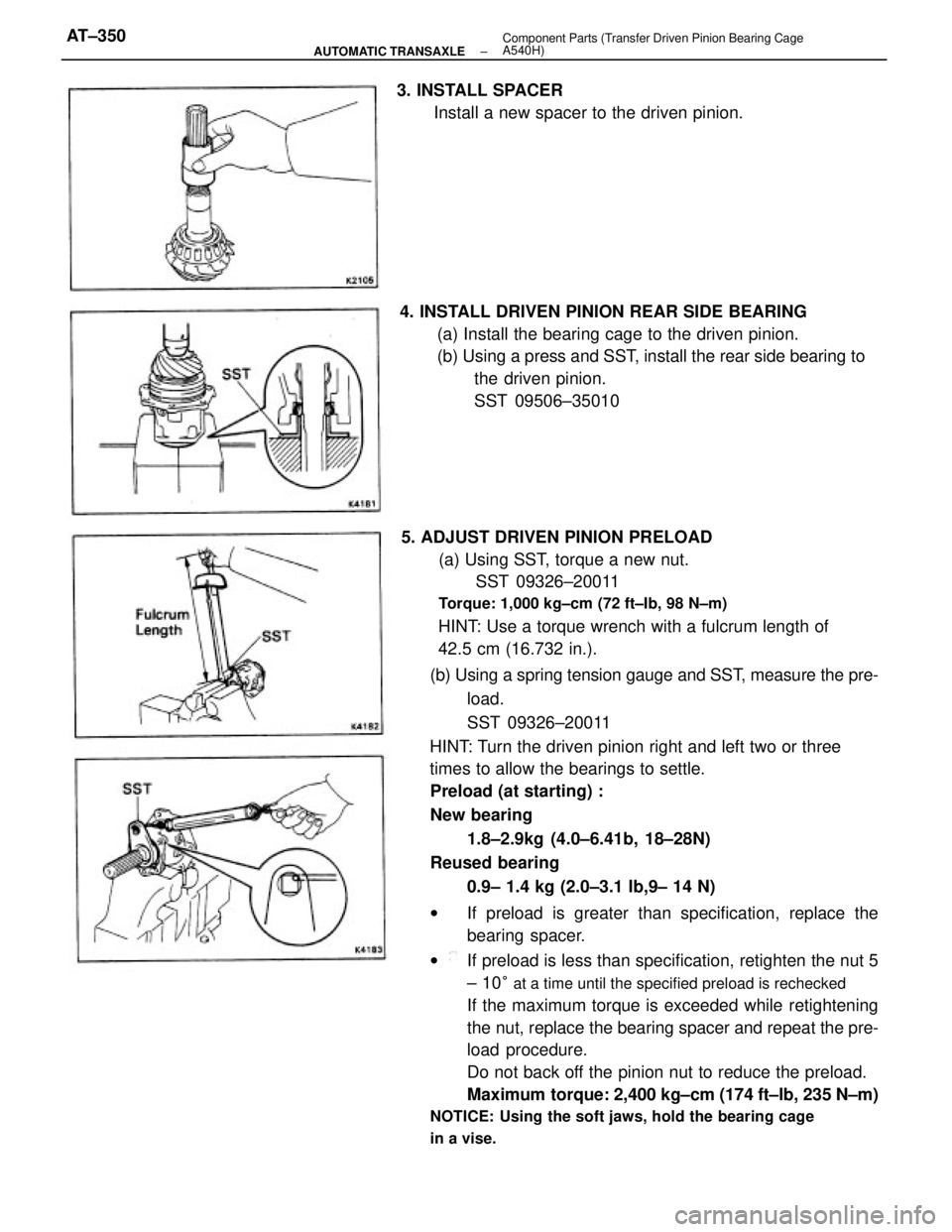
(b) Using a spring tension gauge and SST, measure the pre-
load.
SST 09326±20011
HINT: Turn the driven pinion right and left two or three
times to allow the bearings to settle.
Preload (at starting) :
New bearing
1.8±2.9kg (4.0±6.41b, 18±28N)
Reused bearing
0.9± 1.4 kg (2.0±3.1 Ib,9± 14 N)
wIf preload is greater than specification, replace the
bearing spacer.
wIf preload is less than specification, retighten the nut 5
± 10
° at a time until the specified preload is rechecked
If the maximum torque is exceeded while retightening
the nut, replace the bearing spacer and repeat the pre-
load procedure.
Do not back off the pinion nut to reduce the preload.
Maximum torque: 2,400 kg±cm (174 ft±Ib, 235 N±m)
NOTICE: Using the soft jaws, hold the bearing cage
in a vise.
5. ADJUST DRIVEN PINION PRELOAD
(a) Using SST, torque a new nut.
SST 09326±20011
Torque: 1,000 kg±cm (72 ft±Ib, 98 N±m)
HINT: Use a torque wrench with a fulcrum length of
42.5 cm (16.732 in.). 4. INSTALL DRIVEN PINION REAR SIDE BEARING
(a) Install the bearing cage to the driven pinion.
(b) Using a press and SST, install the rear side bearing to
the driven pinion.
SST 09506±35010 3. INSTALL SPACER
Install a new spacer to the driven pinion.
± AUTOMATIC TRANSAXLEComponent Parts (Transfer Driven Pinion Bearing Cage
A540H)AT±350
Page 592 of 2389
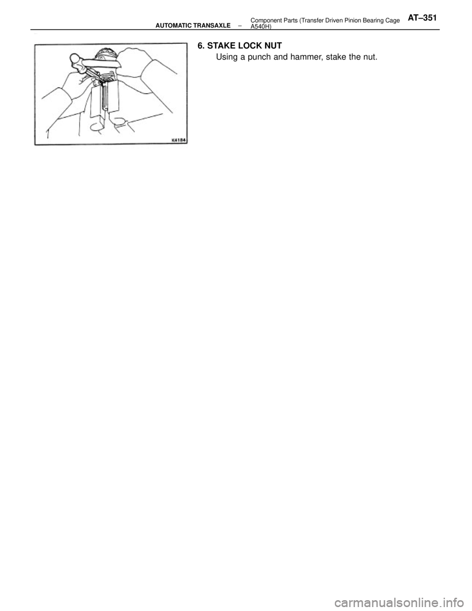
6. STAKE LOCK NUT
Using a punch and hammer, stake the nut.
± AUTOMATIC TRANSAXLEComponent Parts (Transfer Driven Pinion Bearing Cage
A540H)AT±351
Page 593 of 2389
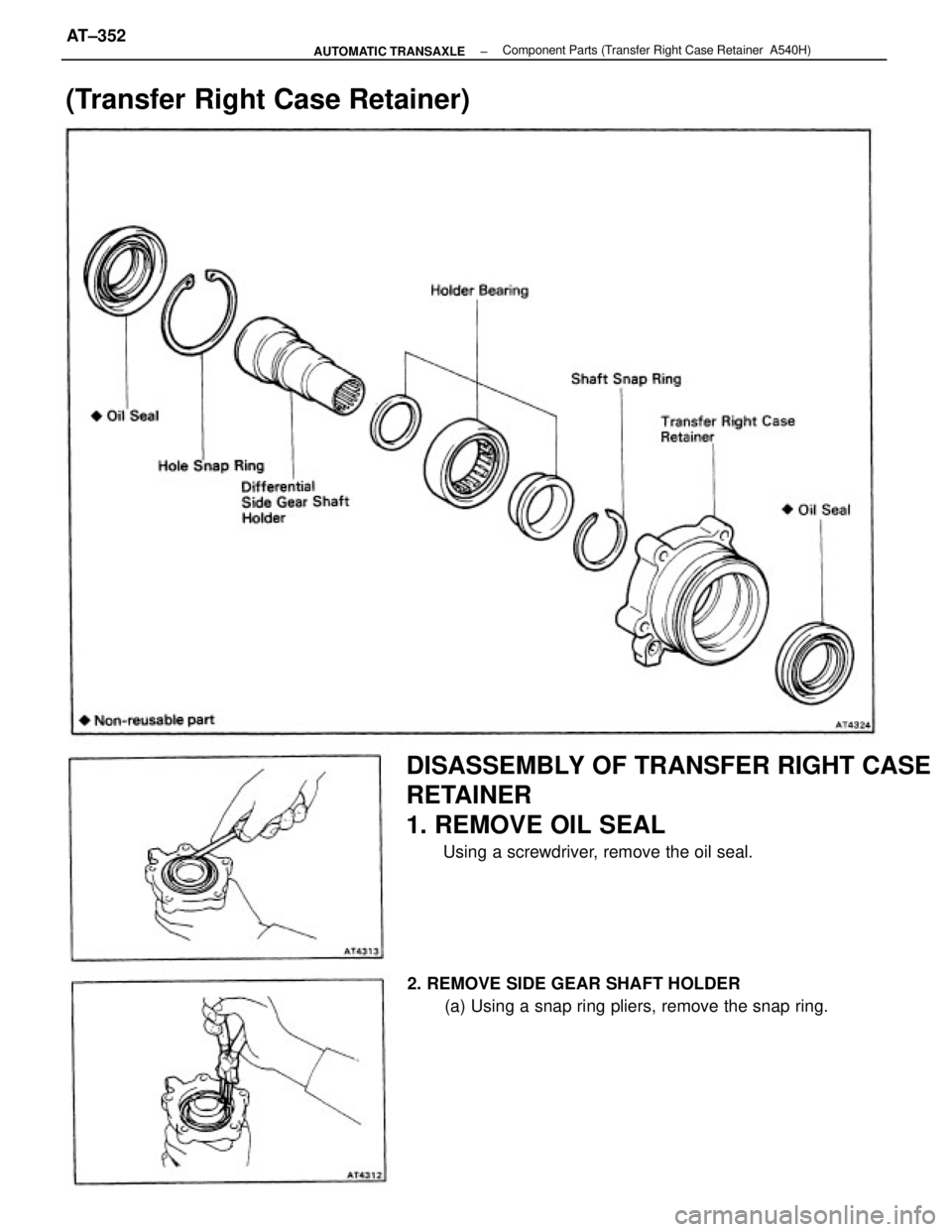
DISASSEMBLY OF TRANSFER RIGHT CASE
RETAINER
1. REMOVE OIL SEAL
Using a screwdriver, remove the oil seal.
2. REMOVE SIDE GEAR SHAFT HOLDER
(a) Using a snap ring pliers, remove the snap ring.
(Transfer Right Case Retainer)
± AUTOMATIC TRANSAXLEComponent Parts (Transfer Right Case Retainer A540H)AT±352
Page 594 of 2389
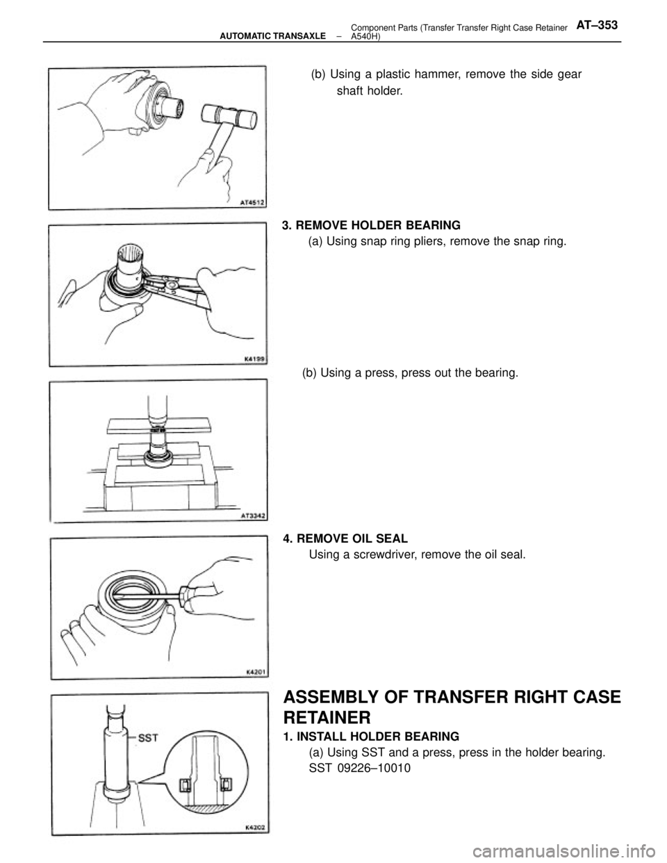
ASSEMBLY OF TRANSFER RIGHT CASE
RETAINER
1. INSTALL HOLDER BEARING
(a) Using SST and a press, press in the holder bearing.
SST 09226±10010 3. REMOVE HOLDER BEARING
(a) Using snap ring pliers, remove the snap ring.(b) Using a plastic hammer, remove the side gear
shaft holder.
4. REMOVE OIL SEAL
Using a screwdriver, remove the oil seal. (b) Using a press, press out the bearing.
± AUTOMATIC TRANSAXLEComponent Parts (Transfer Transfer Right Case Retainer
A540H)AT±353
Page 595 of 2389
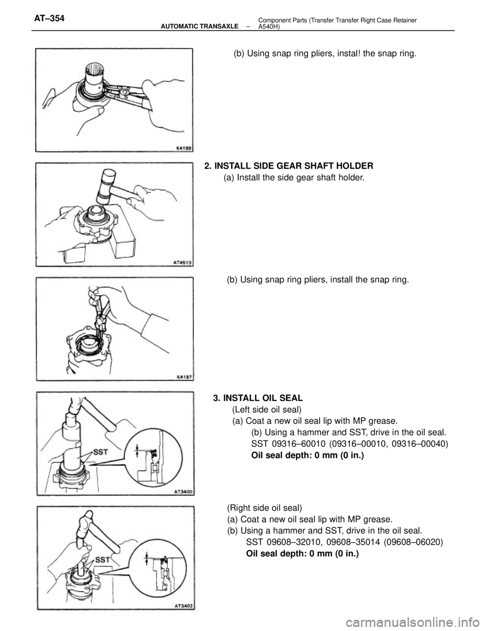
3. INSTALL OIL SEAL
(Left side oil seal)
(a) Coat a new oil seal lip with MP grease.
(b) Using a hammer and SST, drive in the oil seal.
SST 09316±60010 (09316±00010, 09316±00040)
Oil seal depth: 0 mm (0 in.)
(Right side oil seal)
(a) Coat a new oil seal lip with MP grease.
(b) Using a hammer and SST, drive in the oil seal.
SST 09608±32010, 09608±35014 (09608±06020)
Oil seal depth: 0 mm (0 in.) (b) Using snap ring pliers, instal! the snap ring.
2. INSTALL SIDE GEAR SHAFT HOLDER
(a) Install the side gear shaft holder.
(b) Using snap ring pliers, install the snap ring.
± AUTOMATIC TRANSAXLEComponent Parts (Transfer Transfer Right Case Retainer
A540H)AT±354
Page 596 of 2389
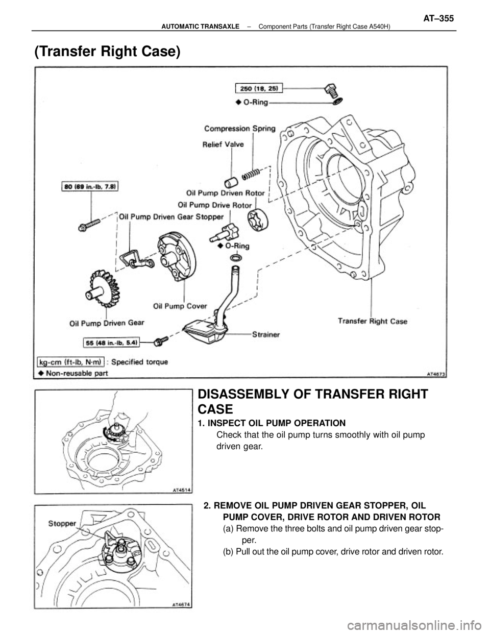
2. REMOVE OIL PUMP DRIVEN GEAR STOPPER, OIL
PUMP COVER, DRIVE ROTOR AND DRIVEN ROTOR
(a) Remove the three bolts and oil pump driven gear stop-
per.
(b) Pull out the oil pump cover, drive rotor and driven rotor.
DISASSEMBLY OF TRANSFER RIGHT
CASE
1. INSPECT OIL PUMP OPERATION
Check that the oil pump turns smoothly with oil pump
driven gear.
(Transfer Right Case)
± AUTOMATIC TRANSAXLEComponent Parts (Transfer Right Case A540H)AT±355
Page 597 of 2389
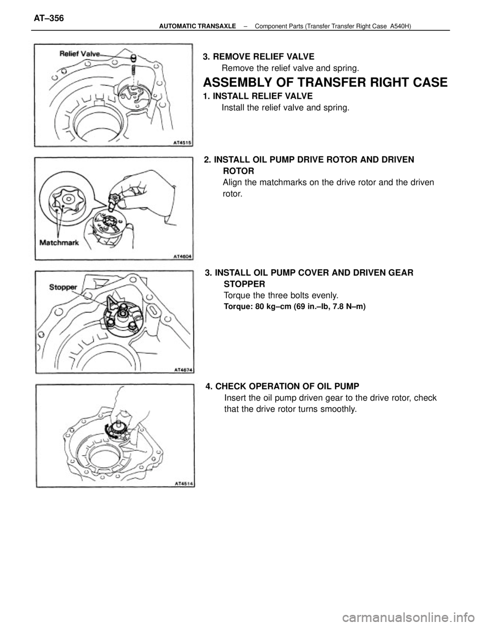
3. REMOVE RELIEF VALVE
Remove the relief valve and spring.
ASSEMBLY OF TRANSFER RIGHT CASE
1. INSTALL RELIEF VALVE
Install the relief valve and spring.
3. INSTALL OIL PUMP COVER AND DRIVEN GEAR
STOPPER
Torque the three bolts evenly.
Torque: 80 kg±cm (69 in.±Ib, 7.8 N±m)
2. INSTALL OIL PUMP DRIVE ROTOR AND DRIVEN
ROTOR
Align the matchmarks on the drive rotor and the driven
rotor.
4. CHECK OPERATION OF OIL PUMP
Insert the oil pump driven gear to the drive rotor, check
that the drive rotor turns smoothly.
± AUTOMATIC TRANSAXLEComponent Parts (Transfer Transfer Right Case A540H)AT±356
Page 598 of 2389
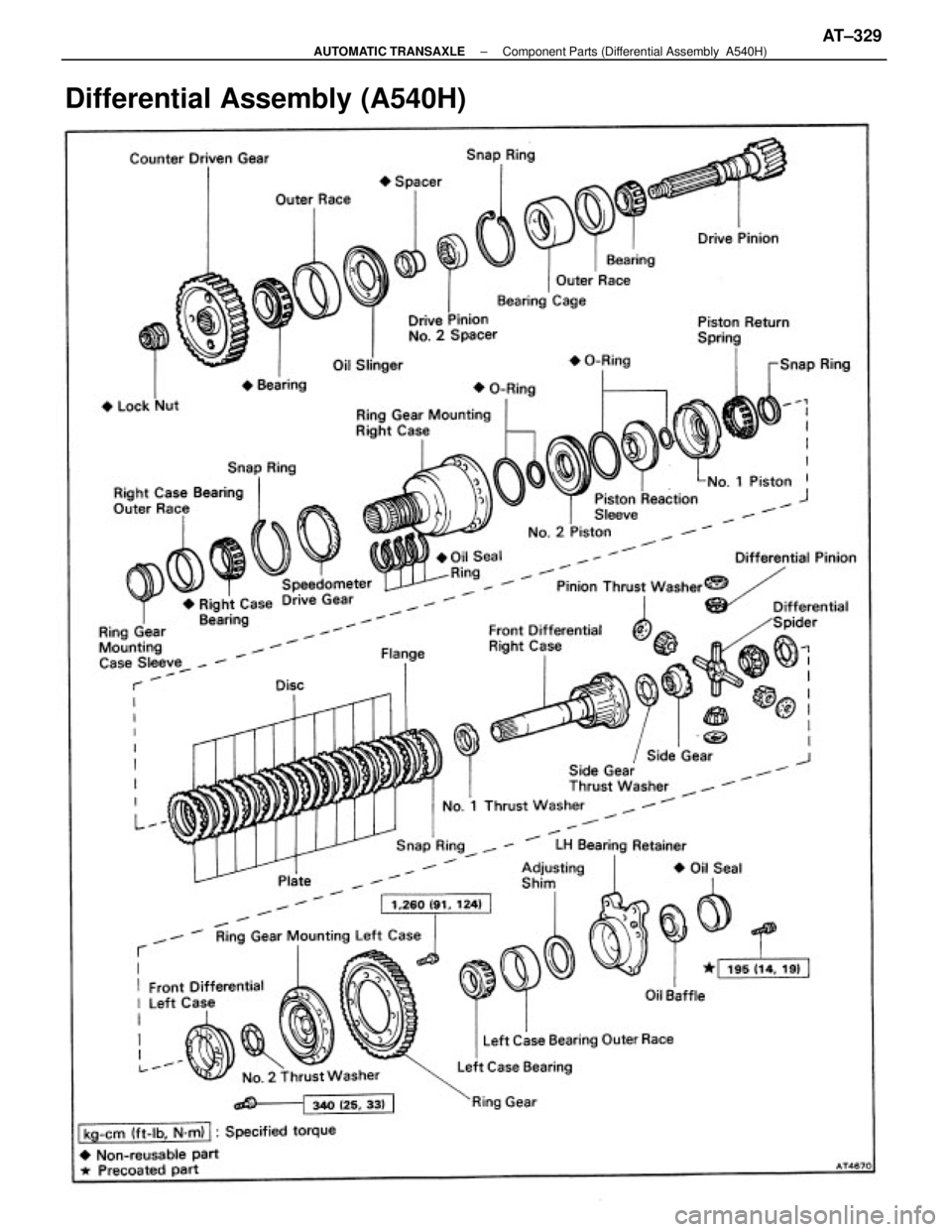
Differential Assembly (A540H)
± AUTOMATIC TRANSAXLEComponent Parts (Differential Assembly A540H)AT±329
Page 599 of 2389
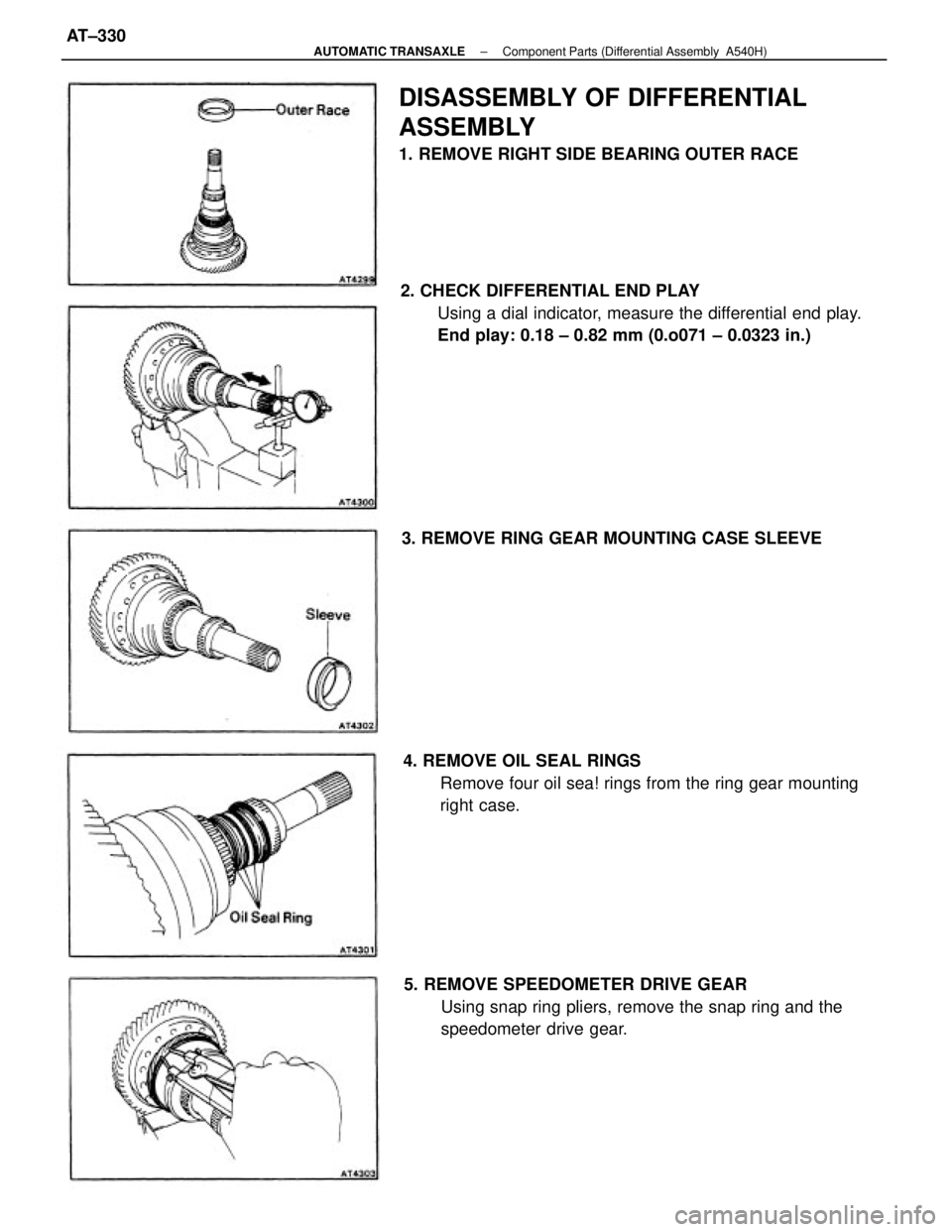
2. CHECK DIFFERENTIAL END PLAY
Using a dial indicator, measure the differential end play.
End play: 0.18 ± 0.82 mm (0.o071 ± 0.0323 in.)
DISASSEMBLY OF DIFFERENTIAL
ASSEMBLY
1. REMOVE RIGHT SIDE BEARING OUTER RACE
4. REMOVE OIL SEAL RINGS
Remove four oil sea! rings from the ring gear mounting
right case.
5. REMOVE SPEEDOMETER DRIVE GEAR
Using snap ring pliers, remove the snap ring and the
speedometer drive gear. 3. REMOVE RING GEAR MOUNTING CASE SLEEVE
± AUTOMATIC TRANSAXLEComponent Parts (Differential Assembly A540H)AT±330
Page 600 of 2389
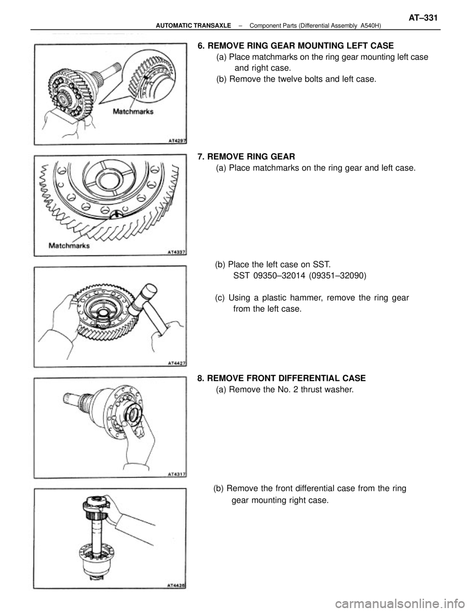
6. REMOVE RING GEAR MOUNTING LEFT CASE
(a) Place matchmarks on the ring gear mounting left case
and right case.
(b) Remove the twelve bolts and left case.
(b) Place the left case on SST.
SST 09350±32014 (09351±32090)
(c) Using a plastic hammer, remove the ring gear
from the left case. 7. REMOVE RING GEAR
(a) Place matchmarks on the ring gear and left case.
(b) Remove the front differential case from the ring
gear mounting right case. 8. REMOVE FRONT DIFFERENTIAL CASE
(a) Remove the No. 2 thrust washer.
± AUTOMATIC TRANSAXLEComponent Parts (Differential Assembly A540H)AT±331
Trending: boot, headlights, washer fluid, seat adjustment, tow bar, seats, wipers

