TOYOTA CAMRY V20 1986 Service Information
CAMRY V20 1986
TOYOTA
TOYOTA
https://www.carmanualsonline.info/img/14/57449/w960_57449-0.png
TOYOTA CAMRY V20 1986 Service Information
Trending: suspension, overheating, boot, fuses, wheel bolt torque, parking sensors, coolant level
Page 611 of 2389
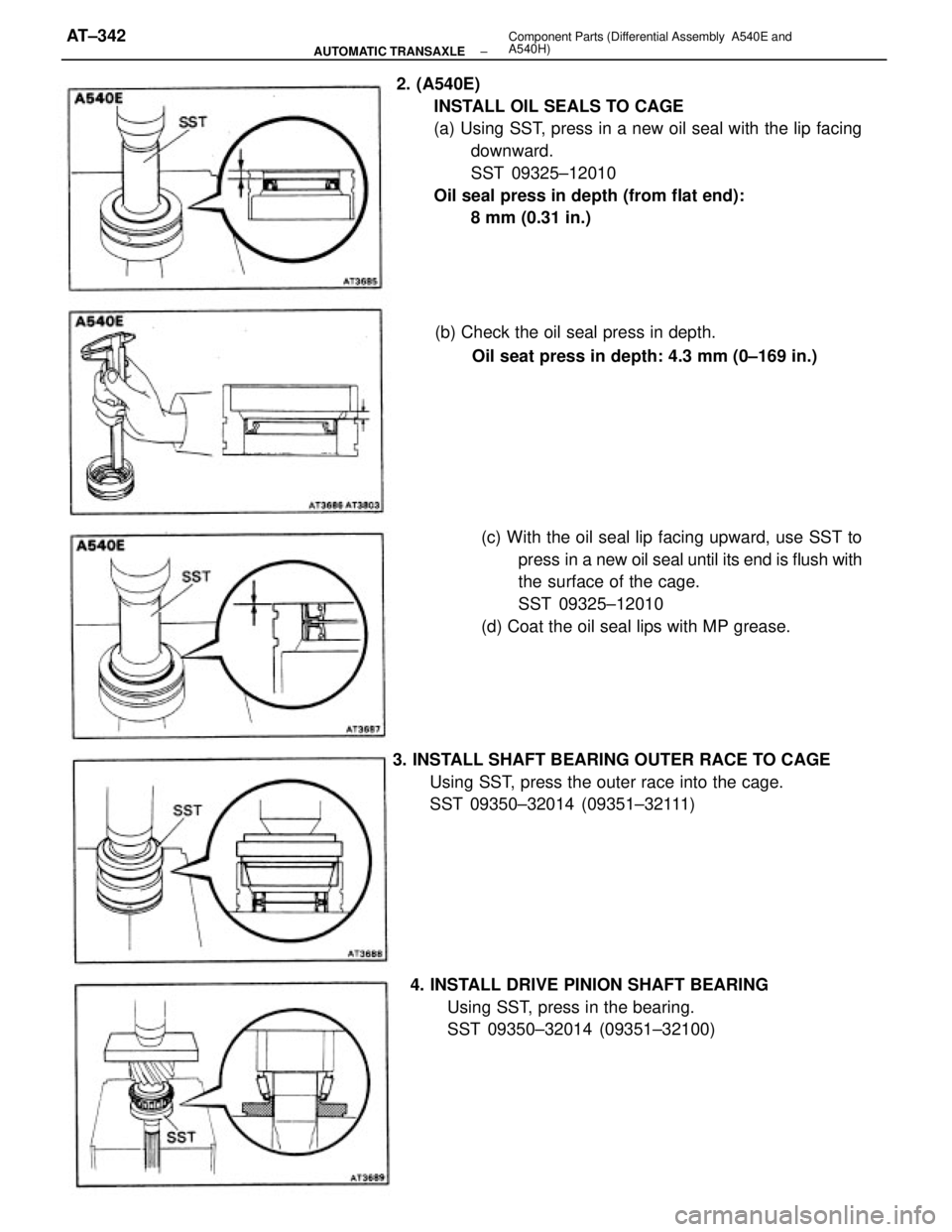
2. (A540E)
INSTALL OIL SEALS TO CAGE
(a) Using SST, press in a new oil seal with the lip facing
downward.
SST 09325±12010
Oil seal press in depth (from flat end):
8 mm (0.31 in.)
(c) With the oil seal lip facing upward, use SST to
press in a new oil seal until its end is flush with
the surface of the cage.
SST 09325±12010
(d) Coat the oil seal lips with MP grease.
3. INSTALL SHAFT BEARING OUTER RACE TO CAGE
Using SST, press the outer race into the cage.
SST 09350±32014 (09351±32111)
4. INSTALL DRIVE PINION SHAFT BEARING
Using SST, press in the bearing.
SST 09350±32014 (09351±32100) (b) Check the oil seal press in depth.
Oil seat press in depth: 4.3 mm (0±169 in.)
± AUTOMATIC TRANSAXLEComponent Parts (Differential Assembly A540E and
A540H)AT±342
Page 612 of 2389
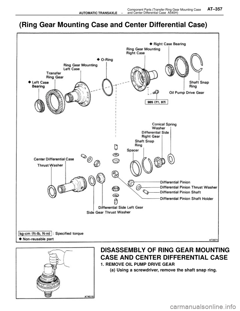
DISASSEMBLY OF RING GEAR MOUNTING
CASE AND CENTER DIFFERENTIAL CASE
1. REMOVE OIL PUMP DRIVE GEAR
(a) Using a screwdriver, remove the shaft snap ring.
(Ring Gear Mounting Case and Center Differential Case)
± AUTOMATIC TRANSAXLEComponent Parts (Transfer Ring Gear Mounting Case
and Center Differential Case A540H)AT±357
Page 613 of 2389
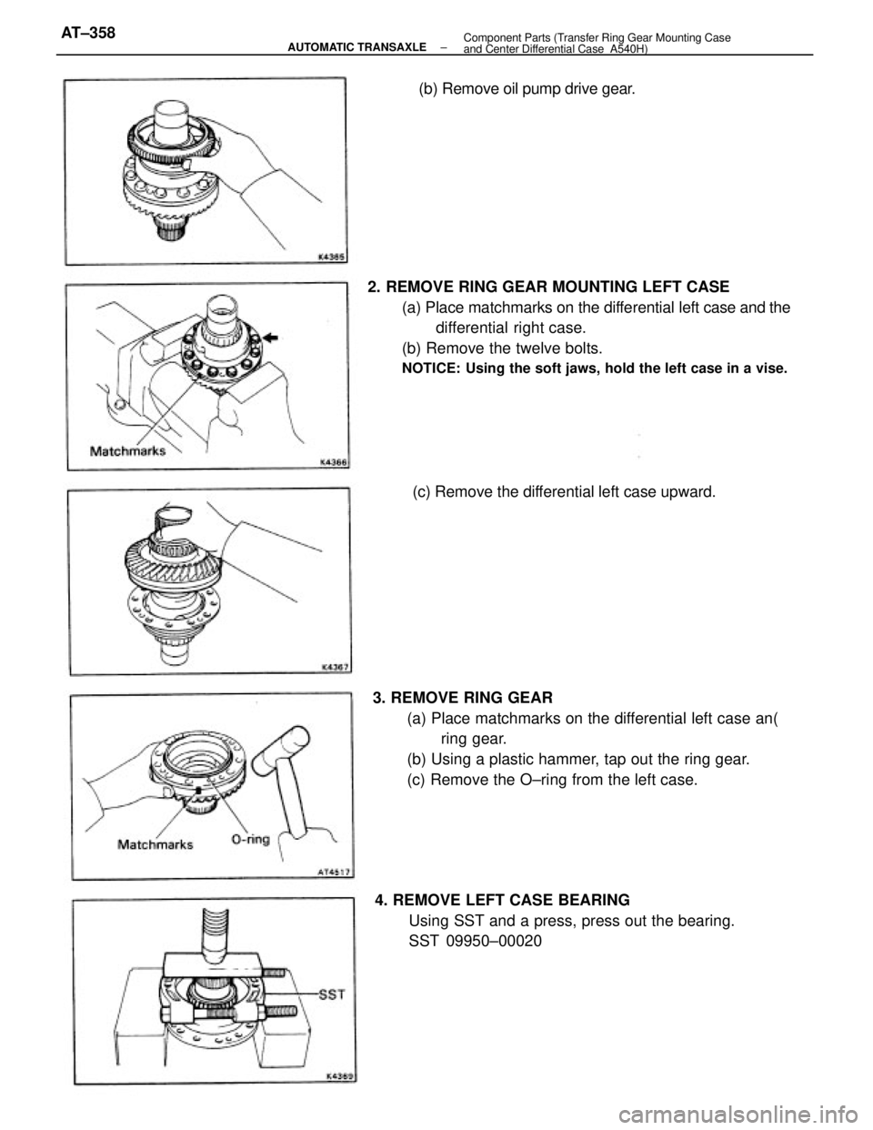
2. REMOVE RING GEAR MOUNTING LEFT CASE
(a) Place matchmarks on the differential left case and the
differential right case.
(b) Remove the twelve bolts.
NOTICE: Using the soft jaws, hold the left case in a vise.
3. REMOVE RING GEAR
(a) Place matchmarks on the differential left case an(
ring gear.
(b) Using a plastic hammer, tap out the ring gear.
(c) Remove the O±ring from the left case.
4. REMOVE LEFT CASE BEARING
Using SST and a press, press out the bearing.
SST 09950±00020(c) Remove the differential left case upward.(b) Remove oil pump drive gear.
± AUTOMATIC TRANSAXLEComponent Parts (Transfer Ring Gear Mounting Case
and Center Differential Case A540H)AT±358
Page 614 of 2389
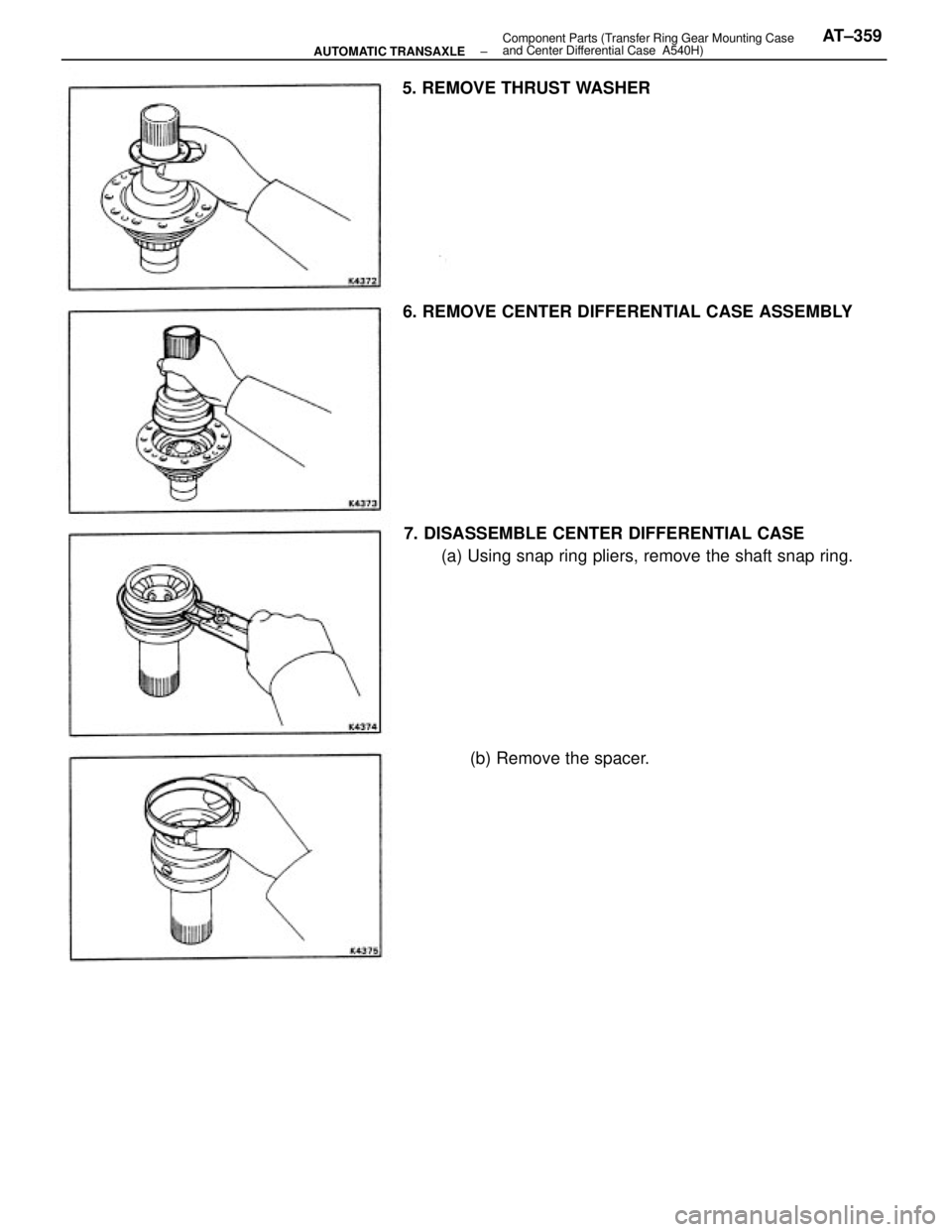
7. DISASSEMBLE CENTER DIFFERENTIAL CASE
(a) Using snap ring pliers, remove the shaft snap ring. 6. REMOVE CENTER DIFFERENTIAL CASE ASSEMBLY 5. REMOVE THRUST WASHER
(b) Remove the spacer.
± AUTOMATIC TRANSAXLEComponent Parts (Transfer Ring Gear Mounting Case
and Center Differential Case A540H)AT±359
Page 615 of 2389
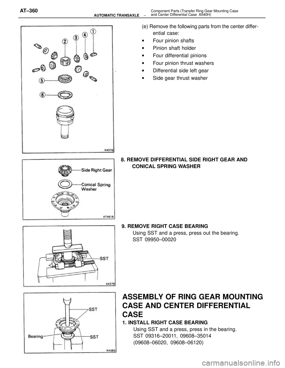
(e) Remove the following parts from the center differ-
ential case:
wFour pinion shafts
wPinion shaft holder
wFour differential pinions
wFour pinion thrust washers
wDifferential side left gear
wSide gear thrust washer
ASSEMBLY OF RING GEAR MOUNTING
CASE AND CENTER DIFFERENTIAL
CASE
1. INSTALL RIGHT CASE BEARING
Using SST and a press, press in the bearing.
SST 09316±20011, 09608±35014
(09608±06020, 09608±06120) 9. REMOVE RIGHT CASE BEARING
Using SST and a press, press out the bearing.
SST 09950±00020 8. REMOVE DIFFERENTIAL SIDE RIGHT GEAR AND
CONICAL SPRING WASHER
± AUTOMATIC TRANSAXLEComponent Parts (Transfer Ring Gear Mounting Case
and Center Differential Case A540H)AT±360
Page 616 of 2389
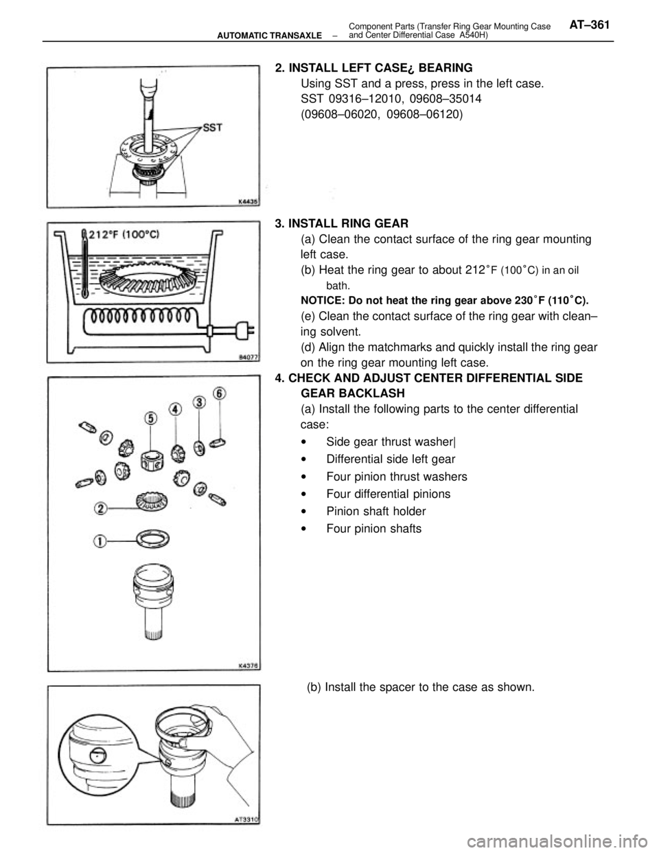
3. INSTALL RING GEAR
(a) Clean the contact surface of the ring gear mounting
left case.
(b) Heat the ring gear to about 212
°F (100°C) in an oil
bath.
NOTICE: Do not heat the ring gear above 230°F (110°C).
(e) Clean the contact surface of the ring gear with clean±
ing solvent.
(d) Align the matchmarks and quickly install the ring gear
on the ring gear mounting left case.
4. CHECK AND ADJUST CENTER DIFFERENTIAL SIDE
GEAR BACKLASH
(a) Install the following parts to the center differential
case:
wSide gear thrust washer|
wDifferential side left gear
wFour pinion thrust washers
wFour differential pinions
wPinion shaft holder
wFour pinion shafts 2. INSTALL LEFT CASE¿ BEARING
Using SST and a press, press in the left case.
SST 09316±12010, 09608±35014
(09608±06020, 09608±06120)
(b) Install the spacer to the case as shown.
± AUTOMATIC TRANSAXLEComponent Parts (Transfer Ring Gear Mounting Case
and Center Differential Case A540H)AT±361
Page 617 of 2389
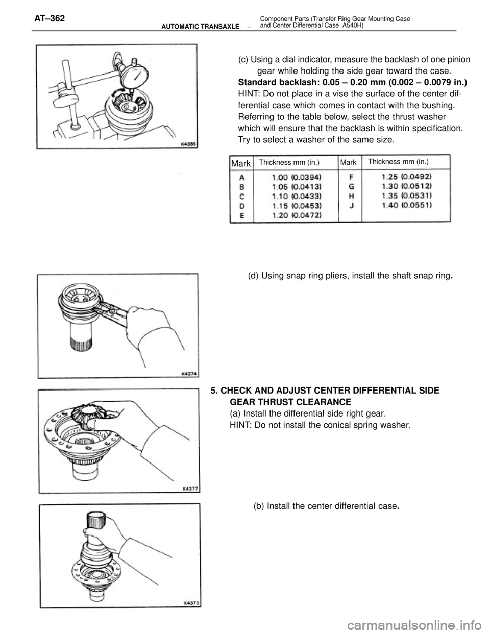
(c) Using a dial indicator, measure the backlash of one pinion
gear while holding the side gear toward the case.
Standard backlash: 0.05 ± 0.20 mm (0.002 ± 0.0079 in.)
HINT: Do not place in a vise the surface of the center dif-
ferential case which comes in contact with the bushing.
Referring to the table below, select the thrust washer
which will ensure that the backlash is within specification.
Try to select a washer of the same size.
5. CHECK AND ADJUST CENTER DIFFERENTIAL SIDE
GEAR THRUST CLEARANCE
(a) Install the differential side right gear.
HINT: Do not install the conical spring washer.(d) Using snap ring pliers, install the shaft snap ring.
(b) Install the center differential case.
Thickness mm (in.)
Thickness mm (in.) MarkMark
± AUTOMATIC TRANSAXLEComponent Parts (Transfer Ring Gear Mounting Case
and Center Differential Case A540H)AT±362
Page 618 of 2389
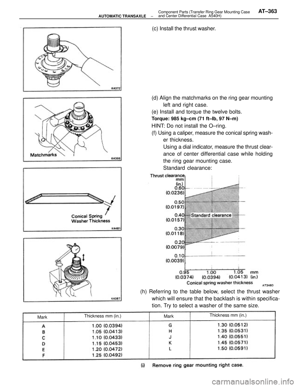
(d) Align the matchmarks on the ring gear mounting
left and right case.
(e) Install and torque the twelve bolts.
Torque: 985 kg±cm (71 ft±Ib, 97 N±m)
HINT: Do not install the O±ring.
(f) Using a caliper, measure the conical spring wash-
er thickness.
Using a dial indicator, measure the thrust clear-
ance of center differential case while holding
the ring gear mounting case.
Standard clearance:
(h) Referring to the table below, select the thrust washer
which will ensure that the backlash is within specifica-
tion. Try to select a washer of the same size.(c) Install the thrust washer.
Thickness mm (in.)Thickness mm (in.)
MarkMark
± AUTOMATIC TRANSAXLEComponent Parts (Transfer Ring Gear Mounting Case
and Center Differential Case A540H)AT±363
Page 619 of 2389
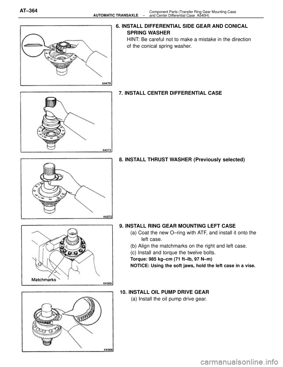
9. INSTALL RING GEAR MOUNTING LEFT CASE
(a) Coat the new O±ring with ATF, and install it onto the
left case.
(b) Align the matchmarks on the right and left case.
(c) Install and torque the twelve bolts.
Torque: 985 kg±cm (71 ft±Ib, 97 N±m)
NOTICE: Using the soft jaws, hold the left case in a vise.
6. INSTALL DIFFERENTIAL SIDE GEAR AND CONICAL
SPRING WASHER
HINT: Be careful not to make a mistake in the direction
of the conical spring washer.
10. INSTALL OIL PUMP DRIVE GEAR
(a) Install the oil pump drive gear. 7. INSTALL CENTER DIFFERENTIAL CASE
8. INSTALL THRUST WASHER (Previously selected)
± AUTOMATIC TRANSAXLEComponent Parts (Transfer Ring Gear Mounting Case
and Center Differential Case A540H)AT±364
Page 620 of 2389
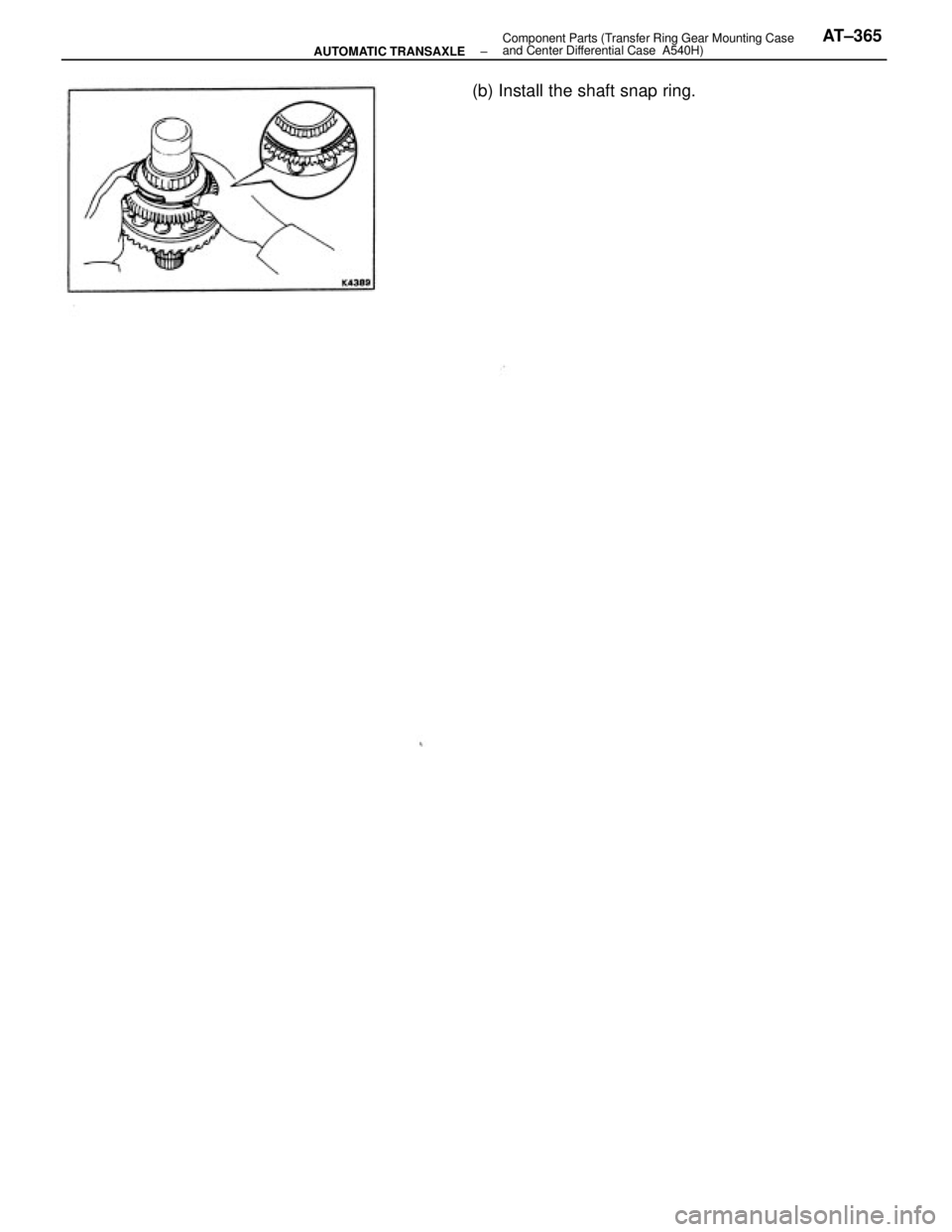
(b) Install the shaft snap ring.
± AUTOMATIC TRANSAXLEComponent Parts (Transfer Ring Gear Mounting Case
and Center Differential Case A540H)AT±365
Trending: engine oil capacity, warning light, height adjustment, seats, overheating, brake light, emergency towing
