TOYOTA CELICA 1987 Service Repair Manual
Manufacturer: TOYOTA, Model Year: 1987, Model line: CELICA, Model: TOYOTA CELICA 1987Pages: 346, PDF Size: 35.13 MB
Page 221 of 346
ENGINE MECHANICAL - CylinderHead
EM&Q
C Front
EX
EM300’
:
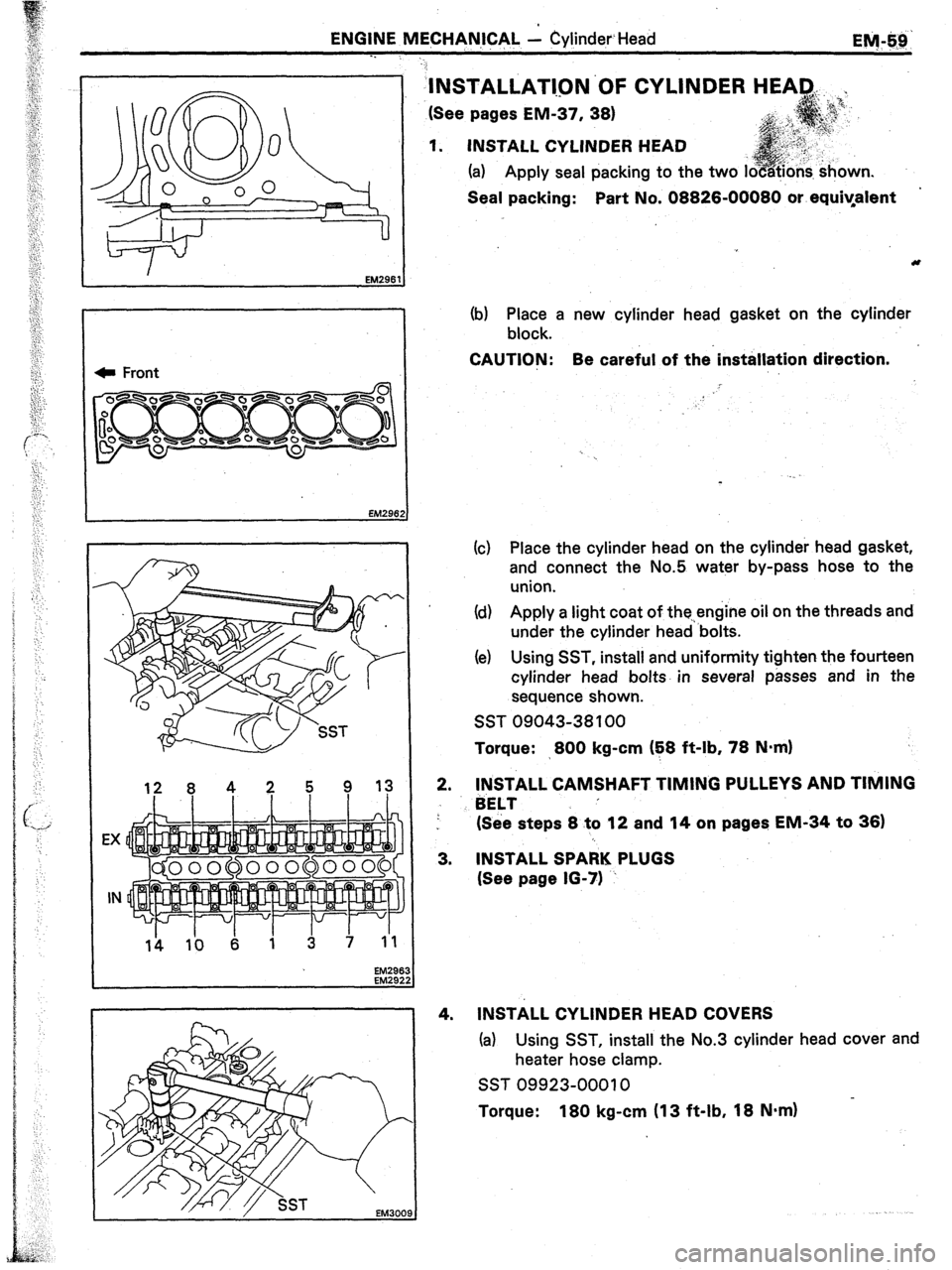
‘INSTALLATl.QN’OF CYLINDER
(See pages EM-37, 38)
1. INSTALL CYLINDER HEAD
(a) Apply seal packing to the two i
Seal packing: Part No. 08826-00080 or equiyafent
(b) Place a new cylinder head gasket on the cylinder
block.
CAUTION: Be careful of the’installation direction.
!
(c) Place the cylinder head on the cylinder head gasket,
and connect the No.5 water by-pass hose to the
union.
Id) Apply a light coat of the.,engine oil on the threads and
under the cylinder head ‘bolts.
(e) Using SST, install and uniformity tighten the fourteen
cylinder head bolts. in several passes and in the
sequence shown.
SST 09043-38 100
Torque: >800 kg-cm (E8 ft-lb, 78 N=m)
2.
3.
4. INSTALL CAMSHAFT TIMING PULLEYS AND TIMING
BELT ’
(See steps 8 to 12 and 14 on pages EM-34 to 36)
INSTALL SPARK PLUGS
(See page 16-71 ~
INSTALL CYLINDER HEAD COVERS
(a) Using SST, install the No.3 cylinder head cover and
heater hose clamp.
SST 09923-00010 in.
Torque: 180 kg-cm (13 ft-lb, 18 N.m)
Page 222 of 346
EM-60
ENGINE MECHANICAL c Cylinder Head
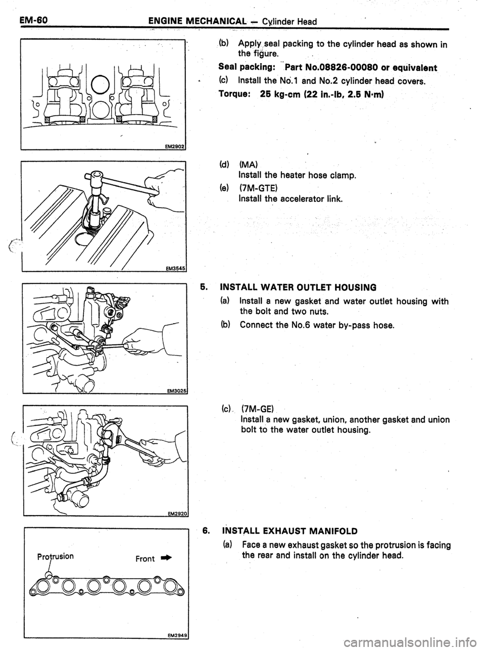
(b) Apply seal packing to the cylinder head as shown in
the figure.
Seal packing: .-Part No.08826-00080 or equivalent
*
(cl Install the No.1 and No.2 cylinder head covers.
Torque: 25 kg-cm (22 in-lb, 2.5 N*m)
(d) (MA)
Install the heater hose clamp.
(e) (7M-GTE)
Install the accelerator link.
5.
INSTALL WATER OUTLET HOUSING
EM302
(a) Install a new gasket and water outlet housing with
the bolt and two nuts.
(b) Connect the No.6 water by-pass hose.
(cl, (7M-GE)
Install a new gasket, union, another gasket and union
bolt to the water outlet housing.
Front * 6. INSTALL EXHAUST MANIFOLD
(a) Face a new exhaust gasket so the protrusion is facing
the rear and install on the cylinder head.
EM2949
Page 223 of 346
ENGINE MECHANICAL- - .Cyli,nder Head
I.
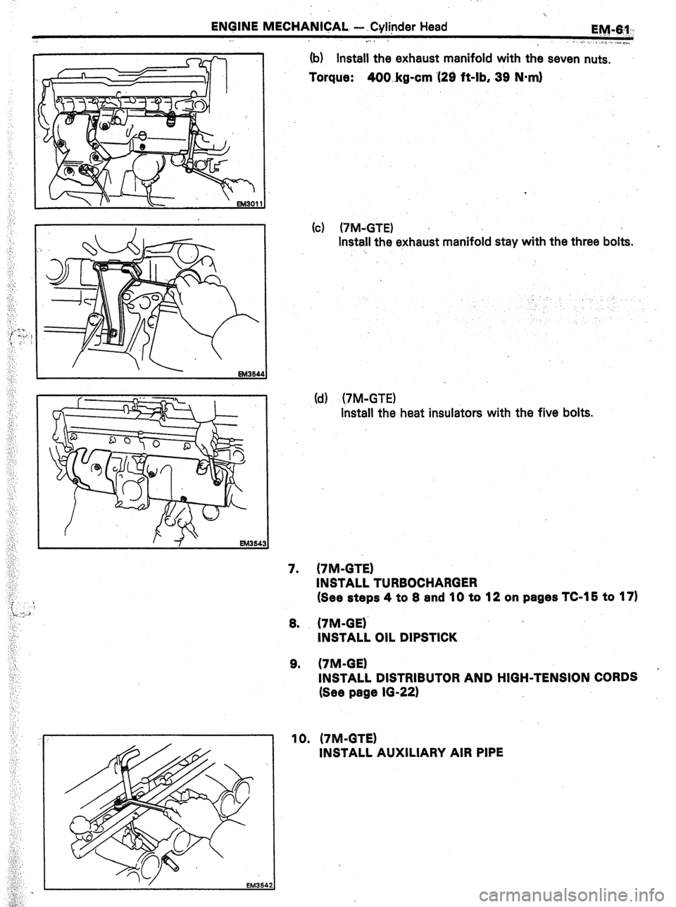
(b) Install the
exhaust manifold with the seven nuts.
Torque: 400.kg-cm ‘(29 ft-lb, 39 N-m)
(c) (7M-GTE)
Install the exhaust manifold stay with the three bolts.
‘.
.(d) (TM-GTE)
install the heat insulators with the five bolts.
7. (7M-GTE)
INSTALL TURBOCHARGER
(See steps 4 to 8 and 10 to 12 on pages TC-15 to 17)
8. (7M-GE)‘
INSTALL OIL DIPSTICK
9. (7M-GE)
.
INSTALL DISTRIBUTOR AND HIGH-TENSION CORDS
(See page 10-22)
Page 224 of 346
EM-62
ENGINE MECHANICAL + Cylinder Head
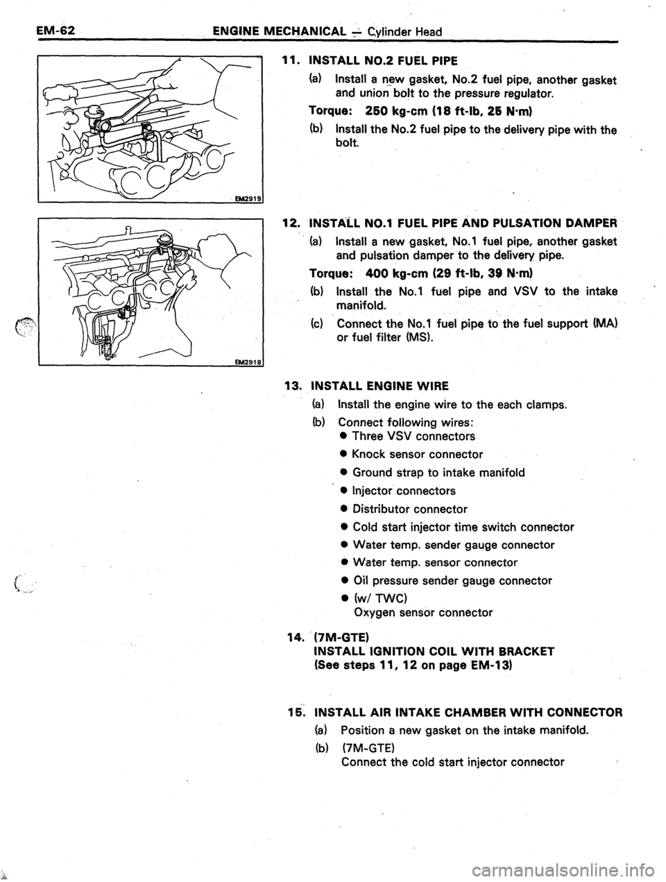
11. INSTALL NO.2 FUEL PIPE
(a) Install a r-13~ gasket, No.2 fuel pipe, another gasket
and union bolt to the pressure regulator.
Torque: 2bO kg-cm (18 ft-lb, 28 N-m)
(b) Install the No.2 fuel pipe to the delivery pipe with the
bolt.
12. INSTALL ~0.1 FUEL PIPE AND PULSATION DAMP&~
(a) Install a new gasket, No.1 fuel pipe, another gasket
and pulsation damper to the delivery pipe.
Torque: 400 kg-cm (29 ft-lb, 39 N*m)
(b) Install the No.1 fuel pipe and VSV to the intake
manifold.
(c) Connect the No.1 fuel pipe to the fuel support (MA)
or fuel filter (MS).
13. INSTALL ENGINE WIRE
(a) Install the engine wire to the each clamps.
(b) Connect following wires:
0 Three VSV connectors
0 Knock sensor connector
0 Ground strap to intake manifold
l Injector connectors
l Distributor connector
l Cold start injector time switch connector
0 Water temp. sender gauge connector
l Water temp. sensor connector
l Oil pressure sender gauge connector
l (w/ nvc)
Oxygen sensor connector
14. (7M-GTE)
INSTALL IGNITION COIL WITH BRACKET
(See steps 11, 12 on page EM-1 31
15. INSTALL AIR INTAKE CHAMBER WITH CONNECTOR
(a) Position a new gasket on the intake manifold.
(b) (7M-GTE)
Connect the cold start injector connector
Page 225 of 346
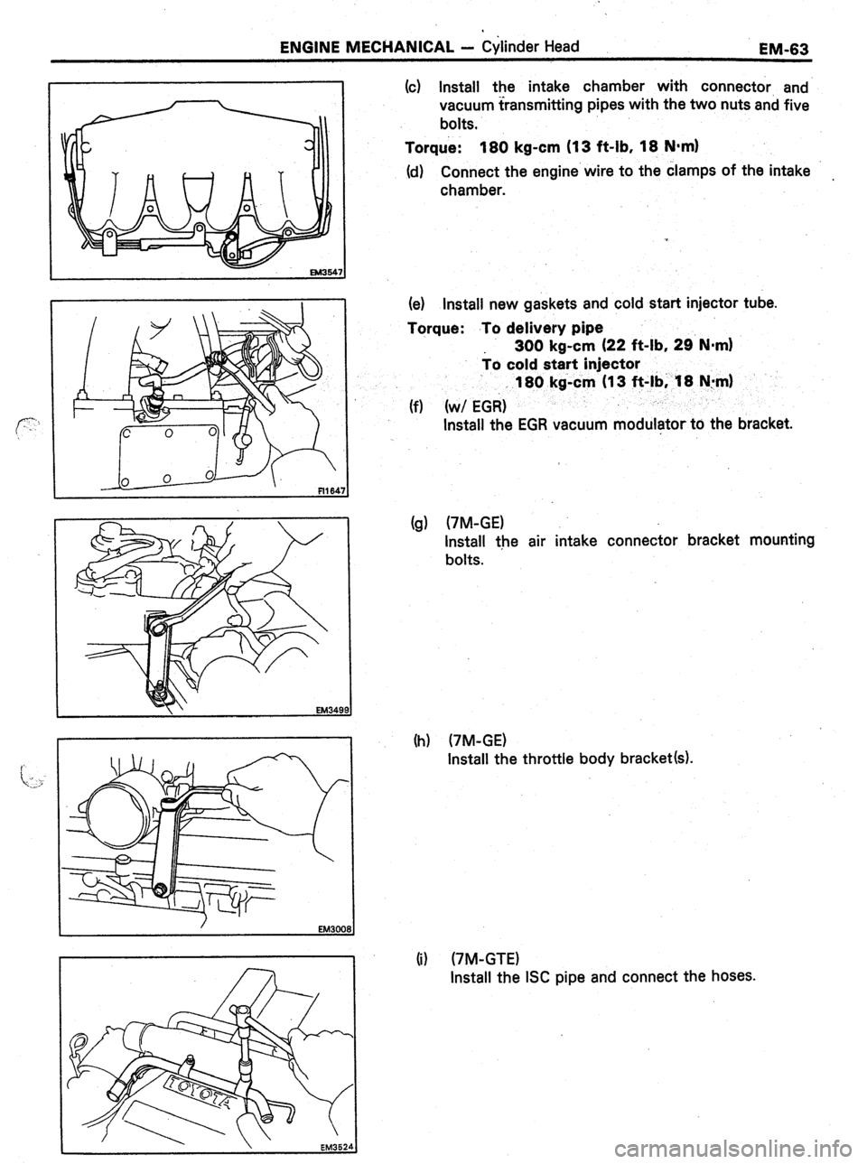
ENGINE MECHANICAL - Cylinder Head
EM-63
(c) Install the intake chamber with connector, and
vacuum transmitting pipes with the two nuts and five
bolts.
Torque: 180 kg-cm (13 f&lb, 18 N-m)
(d) Connect the engine wire to the clamps of the intake
chamber.
(e) install new gaskets and cold start injector tube.
Torque: .To delivery pipe
300 kg-cm (22 f&lb, 29. N-m)
io cold start injector
(f) (w/ EG& 180 kg-cm (I 3 ft-lb; ‘I8 N:m)
Install the EGR vacuum modulator to the bracket.
(g) (7M-GE)
Install the air intake connector bracket mounting
bolts.
(h) (7M-GE)
Install the throttle body bracket(s).
(i) (7M-GTE)
Install the ISC pipe and connect the hoses.
Page 226 of 346
-.
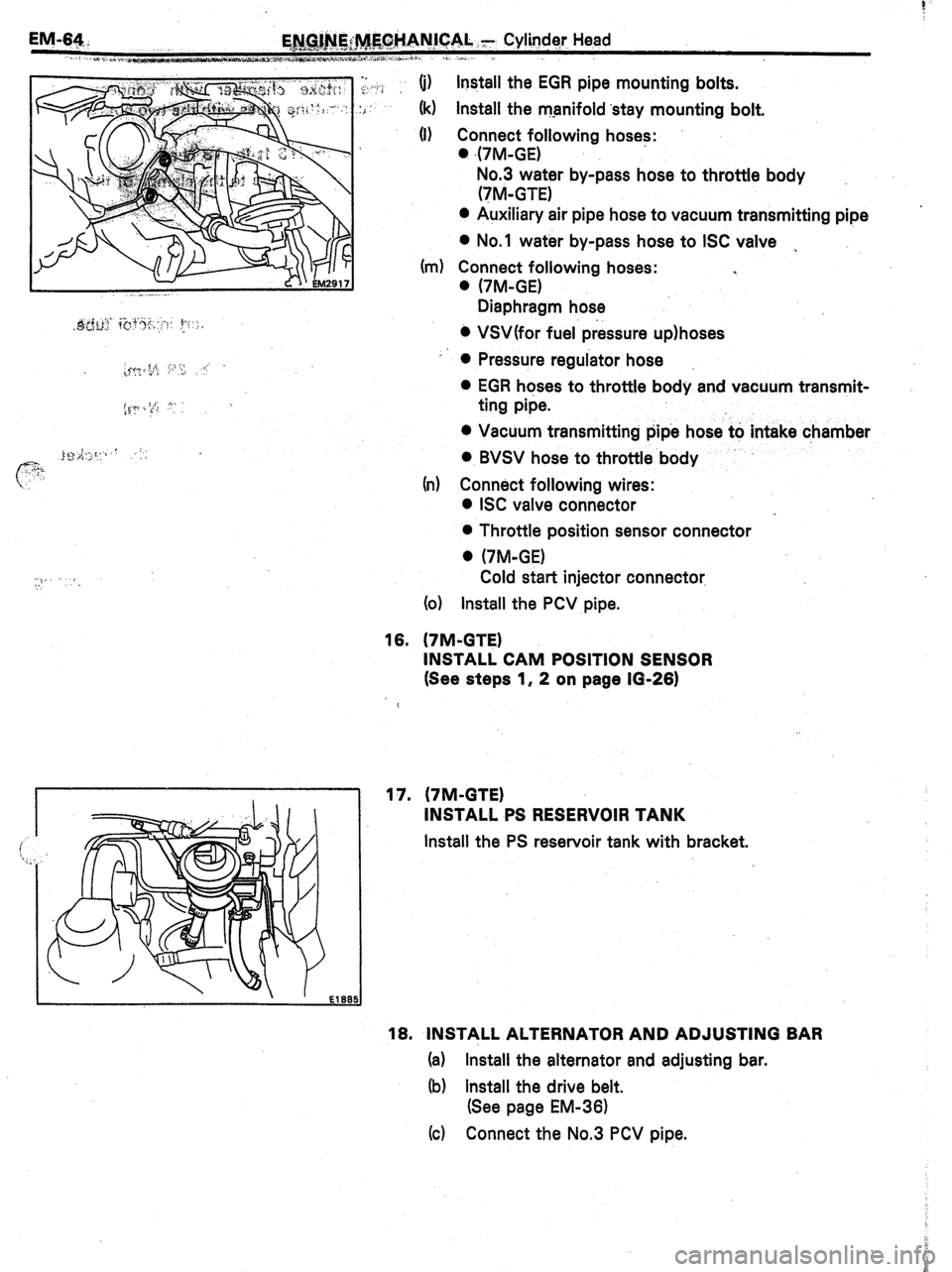
,y. ,. P > .: (i) install the EGR
pipe mounting bolts.
:i
(k) Install the manifold ‘stay mounting bolt.
(I) Connect following hoses:
. 47M-GE)
No.3 water by-pass hose to throttle body
(‘IM-GTE)
0 Auxiliary air pipe hose to vacuum transmitting pipe ’
l No.1 water by-pass hose to ISC valve .
(m) Connect following hoses: .,
. (7M-GE)
Diaphragm hose
0 VSWfor fuel. pressure up)hoses
l Pressure regulator hose
0 EGR hoses to throttle body and vacuum transmit-
ting pipe.
0 Vacuum transmitting pipe hose to intake chamber
-I
0 BVSV hose to throttle body
(r-r) Connect following wires:
0 ISC valve connector
0 Throttle position sensor connector
0 (‘/M-GE)
Cold start injector connector.
(01 Install the PCV pipe.
16. (‘IM-GTE)
INSTALL CAM POSITION SENSOR
(See steps 1, 2 on page 10-26)
17. (7M-GTE)
INSTALL PS RESERVOIR TANK
Install the PS reservoir tank with bracket.
18. INSTALL ALTERNATOR AND ADJUSTING BAR
(a) Install the alternator and adjusting bar.
(b) Install the drive belt.
(See page EM-361
(c) Connect the No.3 PCV pipe.
Page 227 of 346
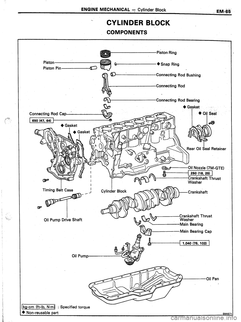
ENGINE MECHANICAL 7 Cylinder Block
7.
CYLINDER BLOCK
COMPONENTS
EM.-6$-
Piston
Piston - + Snap Ring
Connecting Rod Bushing
Connecting Rod Bearing
+ Gasket
t.
Connecting Rod Cap I + Oi! Seal
Rear Oil Seal Retainer
W-Oil Nozzle (7M-GTE)
I
260 (18. 261 I
Crr;;k;aft Thrust
Oil Pump
Page 228 of 346
EM-66 ENGINE MECHANICAL - Cylinder Block
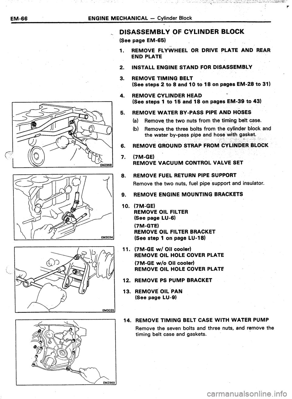
_. DISASSEMBLY OF CYLINDER BLOCK
(See page EM-651
1. REMOVE FLYWHEEL OR DRIVE PLATE AND REAR
END PLATE
2. INSTALL ENGINE STAND FOR DISASSEMBLY
3. REMOVE TIMING BELT
(See steps 2 to 8 and 10 to 18 on pages EM-28 to 31)
4. REMOVE CYLINDER HEAD .I
(See steps 1 to 15 and 18 on pages EM-39 to 43)
5. REMOVE WATER BY-PASS PIPE AND H&ES
(a) Remove. the two nuts from the timing belt case.
(b) Remove.the three bolts from the cylinder block and
the water by-pass pipe and hose with gasket.
__” r
6. REMOVE GROUND STRAP FROlV&Y~l~tiER BLOkK
7. (7M-GE) -
REMOVE VACUUM CONTROL VALVE SET
8. REMOVE FUEL RETURN PIPE SUPPORT
Remove the two nuts, fuel pipe support and insulator.
9. REMOVE ENGINE MOUNTING BRACKETS
10. (‘IM-GE)
REMOVE OIL FILTER
(See page LU-6)
(7M-GTE)
REMOVE OIL FILTER BRACKET
(See step 1 on page LU-18)
11.
12.
13. (7M-GE w/ C#l cooler)
REMOVE OIL HOLE COVER PLATE
(7M-GE w/o Oil cooler)
REMOVE OIL HOLE COVER PLATE
REMOVE PS PUMP BRACKET
REMOVE OIL.PAN
(See page LU-9)
14. REMOVE TIMING BELT CASE WITH WATER PUMP
Remove the seven bolts and three nuts, and r!move the
timing belt case and gaskets.
Page 229 of 346
ENGINE MECHANICAL - Cylinder Block
EM-67
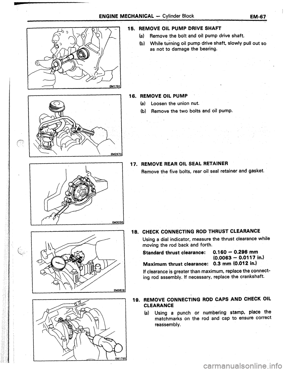
15. REMOVE OIL PUMP DRIVE SHAFT
(a)
Remove the bolt and oil pump drive shaft.
(b) While turning oil pump drive shaft, slowly pull out so
as not to damage the bearing.
16. REMOVE OIL PUMP /
(a) Loosen the union nut.
(b)
Remove the two bolts and oil pump.
17. REMOVE REAR OIL SEAL RETAINER
Remove the five bolts, rear oil seal retainer and gasket.
18. CHECK CONNECTING ROD THRUST CLEARANCE
Using a dial indicator, measure the thrust clearance while
moving the rod back and forth.
Standard thrust clearance:
0.160 - 0.296 mm
(0.0063 - .0.0117 in.)
Maximum thrust clearance:
0.3 mm (0.012 in.)
If clearance is greater than maximum, replace the connect-
ing rod assembly. If necessary, replace the crankshaft.
19. REMOVE CONNECTING ROD CAPS AND CHECK OIL
CLEARANCE
Ia) Using a punch or numbering stamp, place the
matchmarks on the rod and cap to ensure correct
reassembly.
Page 230 of 346
EM-68 . ENGINE MECHANICAL - ,Cylinder Block
EM39
J ,32
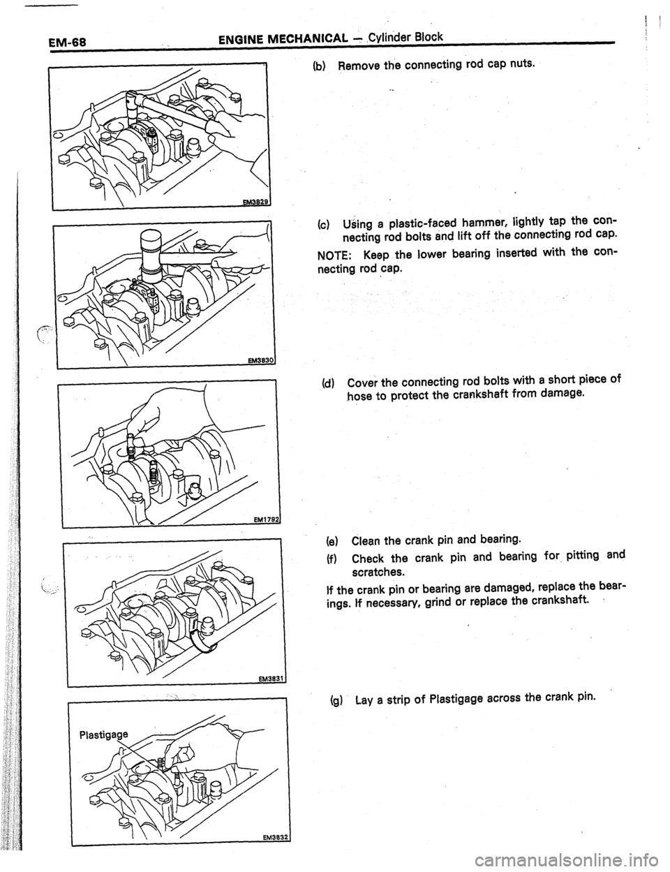
(b) Remove the connecting rod cap nuts.
(c) Using a plastic-faced hammer, lightly tap the con-
necting rod bolts and lift off the connecting rod cap.
NOTE: Keep the lower bearing inserted with the con-
necting rod cap.
(d) Cover the connecting rod bolts with a short piece of
,hose to protect the crankshaft from damage.
(e) Clean the crank pin and bearing.
(f) Check the crank pin and bearing for. pitting and
scratches.
If the crank pin or bearing are damaged, replace the bear-
ings. If necessary, grind or replace the crankshaft.
(g) Lay a strip of Plastigage across the crank pin.