TOYOTA CELICA 1987 Service Repair Manual
Manufacturer: TOYOTA, Model Year: 1987, Model line: CELICA, Model: TOYOTA CELICA 1987Pages: 346, PDF Size: 35.13 MB
Page 251 of 346
ENGINE MECHANICAL A Cylinder Block
EM-@-
3.
4.
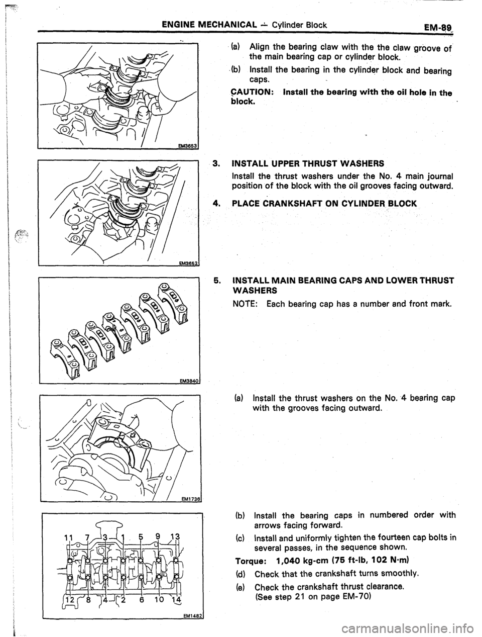
5. (a)
Align the bearing claw with the the claw -groove of.
the main bearing cap or cylind,er block.
(b)
Install the bearing in the cylinder block and bearing
caps.
GAUTION:
Install the bearing with the oil hole in the
block.
INSTALL UPPER THRUST WASHERS
Install the thrust washers under the No. 4 main journal
position of the block with the oil grooves facing outward.
PLACE &ANKSHAFT ON CYLINDER BLOCK
INSTALL MAIN BEARING CAPS AND LOWER THRUST
WASHERS
NOTE: Each bearing cap has a number and front mark.
(a) Install the thrust washers on the No. -4 bearing cap
with the grooves facing outward.
(b) Install the bearing caps in numbered order with
arrows facing forward.
(c) Install and uniformly tighten the fourteen cap bolts in
several passes, in the sequence shown.
Torque: 1,040 kg-cm (75 ft-lb, 102 N.mI
(d) Check that the crankshaft turns smoothly.
(e) Check the crankshaft thrust clearance.
(See step 21 on page EM-701
Page 252 of 346
EM-90 ENdIM IV~ECHAN~CAL - Cylinder Block
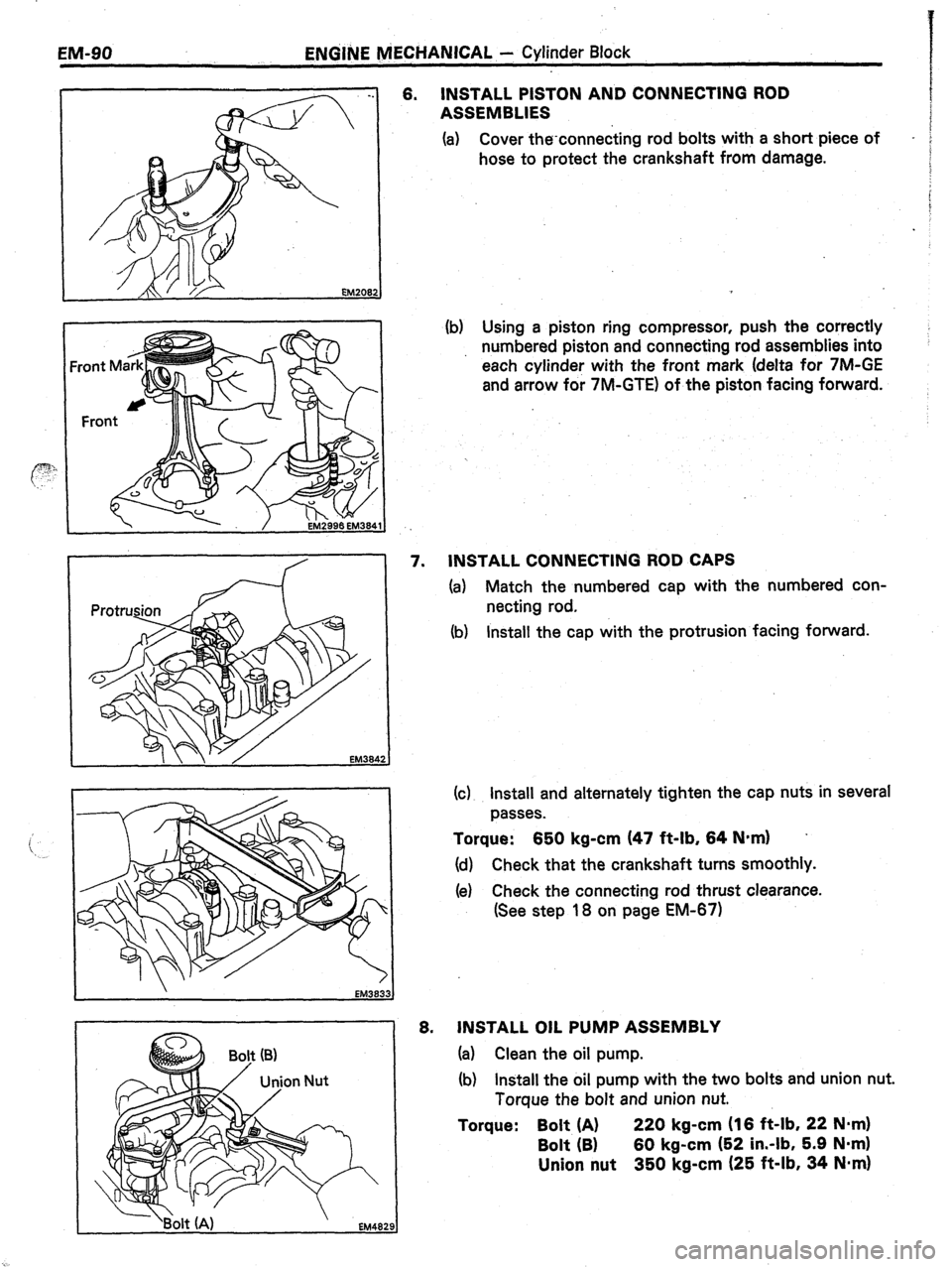
6. INSTALL PISTON AND CONNECTING ROD
ASSEMBLIES
(a) Cover the-connecting rod bolts with a short piece of
-
hose to protect the crankshaft from damage.
(b) Using a piston ring compressor, push the correctly
numbered piston and connecting rod assemblies into
each cylinder with the front mark (delta for 7M-GE
and arrow for 7M-GTE) of the piston facing forward.
EM384
EM383.
EM482
7. INSTALL CONNECTING ROD CAPS
(a) Match the numbered cap with the numbered con-
necting rod.
(b) Install the cap with the protrusion facing forward.
(c) Install and alternately tighten the cap nuts in several
passes.
Torque: 650 kg-cm (47 ft-lb, 64 N-m) .
(d) Check that the crankshaft turns smoothly.
(e) Check the connecting rod thrust clearance.
(See step 18 on page EM-671
6. JNSTALL OIL PUMP ASSEMBLY
(a) Clean the oil pump.
(b) Install the oil pump with the two bolts and union nut.
Torque the bolt and union nut.
Torque: Bolt (A) 220 kg-cm (16 ft-lb, 22 N*m)
Bolt (B) 60 kg-cm (52 in.-lb, 5.9 Nom)
Union nut 350 kg-cm (25 ft-lb, 34 Nmrn)
Page 253 of 346
ENGINE MECHANICAL - Cylinder Block
Qy g&
.
e. .-. .a ,j .a. VI ,... :~.~.**-.-. ),
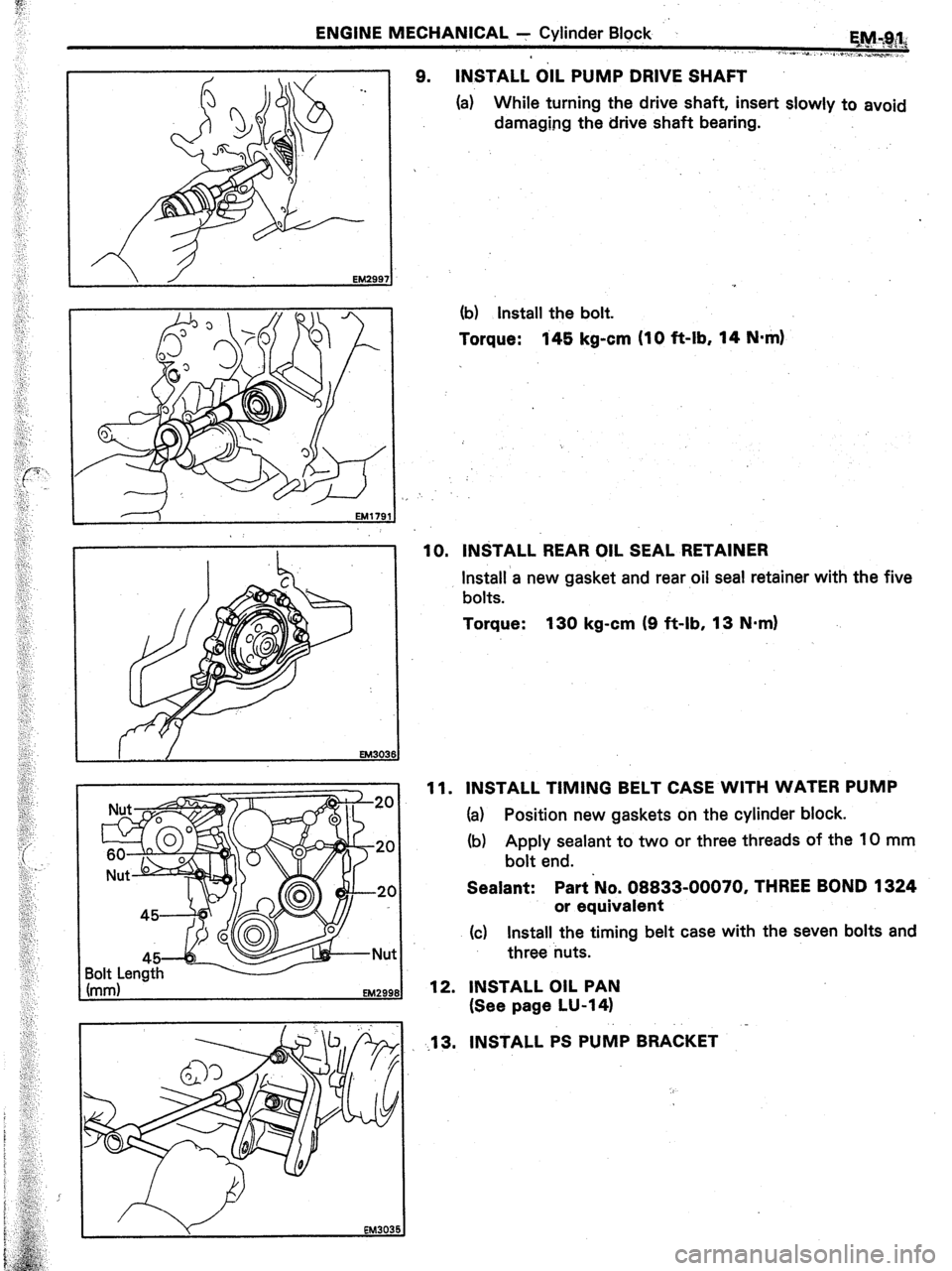
9. INSTALL OIL PUMP DRIVE SHAFT
(a) While turning the drive shaft, insert slowly to avoid
damaging the drive shaft bearing.
(b) Install the bolt.
Torque:
145 kg-cm (10 ft-lb, 14 N*m)
10. INSTALL REAR OIL SEAL RETAINER
Install
a new gasket and rear oil seal retainer with the five
bolts.
Torque: 130 kg-cm (9 ft-lb, 13 N.m)
11. INSTALL TIMING BELT CASE WITH WATER PUMP
(a) Position new
gaskets on the cylinder block.
(b) Apply sealant to two or three threads of the 10 mm
bolt end.
Sealant: Part No. 08833-00070, THREE BOND 1324
or equivalent
(c) Install the timing belt case with the seven bolts and
three nuts.
12. INSTALL OIL PAN
(See page LU-14)
.13. INSTALL PS PUMP BRACKET
Page 254 of 346
EM-92 _. ENGINE MECHANICAL +’ Cylinder Block
-..
: .
;,,
“.’
‘i4. (7M-GE w/ Oil Cooler)
INSTALL Oil.. REGULATOR
Install a new gasket and oil regulator with. the two bolts.
(7M-GE w/o Oil Cooler and.7M-GTE)
INSTALL OIL HOLE COVER PLATE
Install a new gasket and oil hole cover plate with the two .
bolts.
15. (7M-GE)
INSTALL NEW OIL FILTER
(See page LU-6)
16. INSTALL ENGlNE MOUNTING BRACKETS
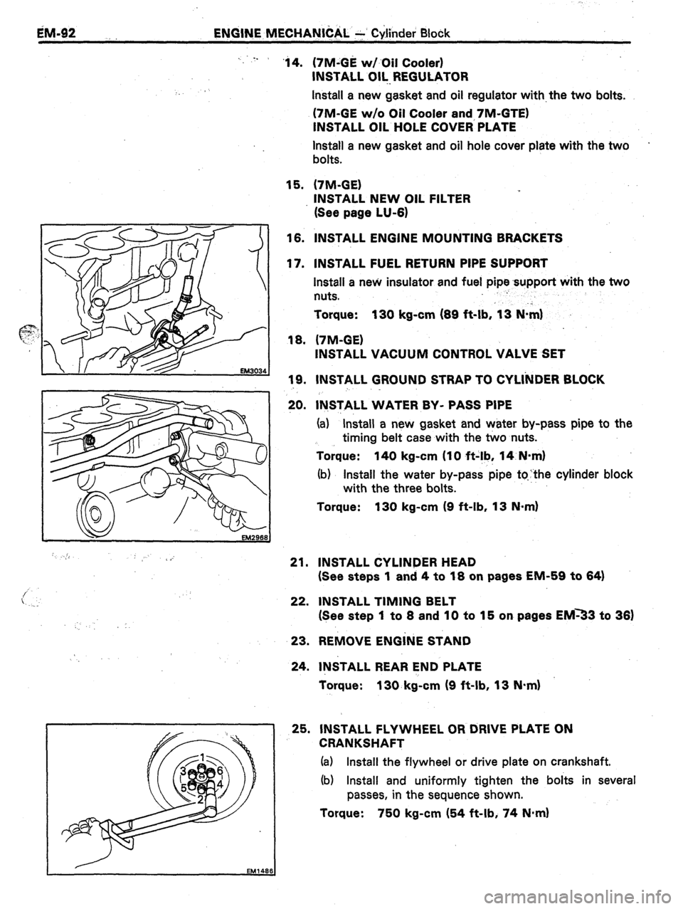
17. INSTALL FUEL RETURN PIPE SUPPORT
Install a new insulator and fuel pipe support with the two
nuts. :
Torque: 130 kg-cm (69 ft-lb, ‘1.3 N&l
18. (7M-GE)
INSTALL VACUUM CONTROL VALVE SET
19. INSTALL GROUND STRAP TO CYLI’NDER BLOCK
20. lN,STALL WATER BY- PASS PIPE
(a) “Install a new gasket and water by-pass pipe to the
timing belt case with the two nuts.
Torque: 140 kg-cm (IO ft-!b, 14 N-m)
(b) Install the water by-pass pipe tqthe cylinder block
with the three bolts.
Torque: 130 kg-cm (9 ft-lb, 13 N-m)
21. INSTALL CYLINDER HEAD
(See steps 1 and 4 to 18 on pages EM-59 to 64)
22. INSTALL TIMING BELT
(See step 1 to 8 and 10 to 15 on pages EM33 to 36)
23. REMOVE ENGiNE STAND
24. INSTALL REAR END PLATE
Torque: 130. kg-cm (9 ft-lb, 13 N.m)
25. INSTALL FLYWHEEL OR DRIVE PLATE ON
CRANKSHAFT
(a) Install the flywheel or drive plate on crankshaft.
(b) Install and uniformly tighten the bolts in several
passes, in the sequence shown.
Torque: 750 kg-cm (54 ft-lb, 74 N*m)
Page 255 of 346
. .
-.
.’ .,
-.. . . t .’
. . . ,..
1.1 .I.. -I ““... _.. ____ ,,_
_ ..I,. ..-. It
_-
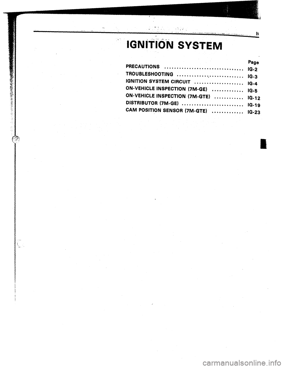
IGNiiid’N SYSTEM
PRECAUTIONS Page
................................
16-2
TROUBLESHOOTING
............................
IG-3
IGNITION SYSTEM CIRCUIT
....................
ON-VEHICLE INSPkTlON (7M-GE) IO-4
............. IO-5
ON-VEHICLE INSPECTION (7M-GTE)
............ IO-1 2
DISTRIBUTOR (7M-GE)
.........................
IO-19
CAM POSITION SENSOR (7M-GTE)
............. 16-23
Page 256 of 346
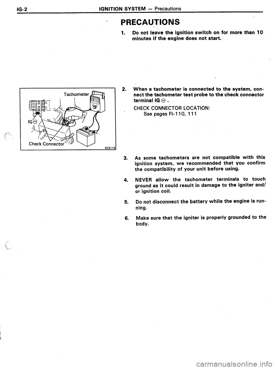
16-2 IGNITION SYSTEM - precautions
-.
PRECAUTIONS
1.
2.
3.
4.
5.
6.
. *
Do not leave the ignition switch on for more than 10
minutes if the engine does not start.
When a tachometer is connected to the system; con-
nect the tachometer test probe to the check connector
terminal IG 0 .
CHECK CONNECTOR LOCATION:
See pages FI-110, 111
As some tachometers are not compatible with this
ignition system, we recommended that you confirm
the compatibility of your unit before using.
NEVER allow the tachometer terminals to touch
ground as it could result in damage to the igniter and/
or ignition coil.
Do not disconnect the battery while the engine is run-
ning.
Make sure that the igniter is properly grounded to the
body.
Page 257 of 346
:on-
ztor
thi
‘irr
‘UC
mc
WI
tf
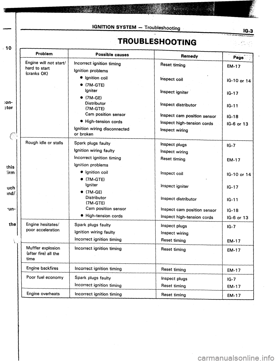
Problem
Engine will not star-t/
hard to start
(cranks OK)
Rough idle or stalls
Engine hesitates/
poor acceleration
Muffler explosion
(after fire) all the
time
Engine backfires
Poor fuel economy
Engine overheats
TROUBLESHOOTING
Possible causes
Incorrect ignition timing
Ignition problems
0 Ignition coil
. (7M-GTE)
Igniter
. (7M-GE)
Distributor
(7M-GTE)
Cam position sensor
l High-tension cords
Ignition wiring disconnected
or broken
Spark plugs faulty
Ignition wiring faulty
Incorrect ignition timing
Ignition problems
0 Ignition coil
. I7M-GTE)
Igniter
. (7M-GE)
Distributor
(7M-GTE)
Cam position sensor
0 High-tension cords
Spark plugs faulty
Ignition wiring faulty
Incorrect ignition timing
Incorrect ignition timing
Incorrect ignition timing
Spark plugs faulty
Incorrect ignition timing
Incorrect ignition timing Remedy
Reset timing
lrkpect coil
Inspect igniter
Inspect distributor
Inspect cam position sensor
Inspect high-tension cords
Inspect wiring
Inspect plugs
Inspect wiring
Reset timing
Inspect coil
Inspect igniter
Inspect distributor
Inspect cam position sensor
Inspect high-tension cords
Inspect plugs
Inspect wiring
Reset timing
Reset timing
Reset timing
Inspect plugs
Reset timing
Reset timing =
Page-.. :
-
EM-17
IG-10 or 14
IG-17
IG-11
IG-1%
IG-6 or 13
IG-7
EM-l 7
IG-10 or 11
IG-17
IG-I 1
IG-18
IG-6 or 13
IG-7
EM-l 7
EM-1 7
Page 258 of 346
IQ-4
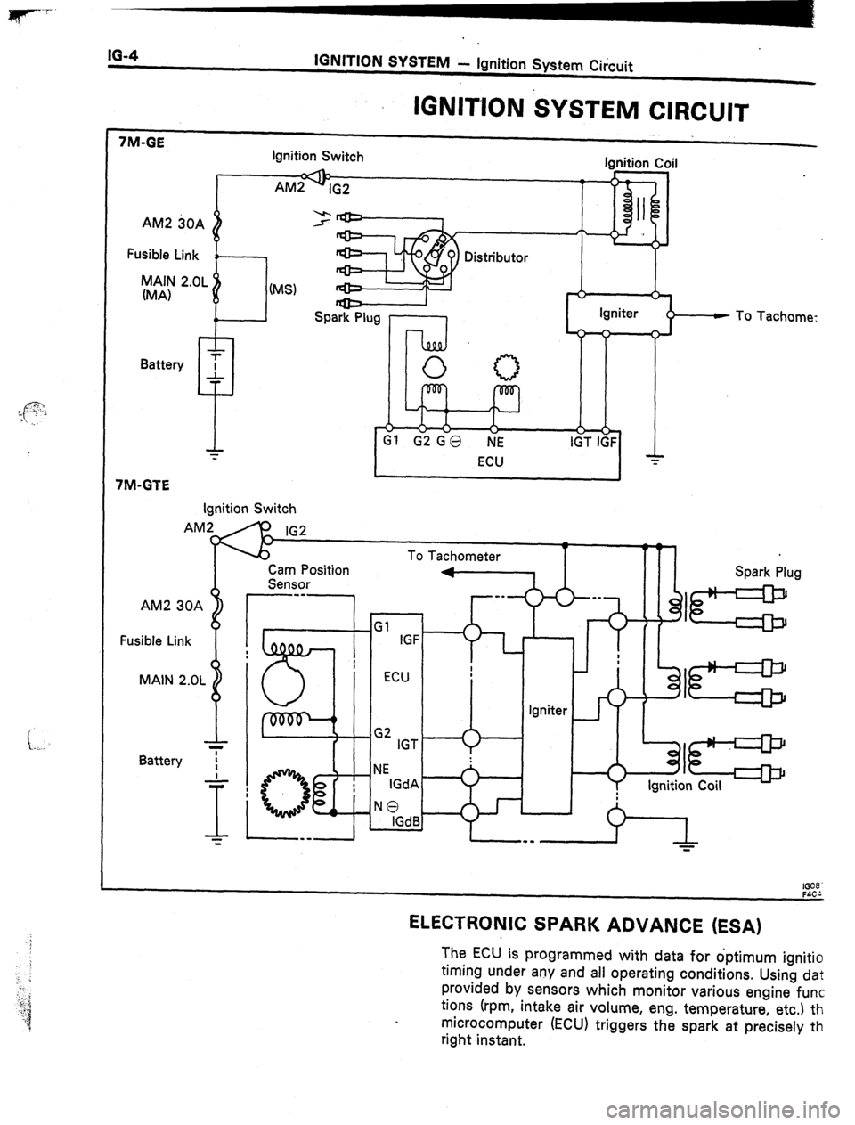
IGNITION SYSTEM - Ignition System Circuit
IGNlTlON SYSTEM CIRCUIT
7M-GE, Ignition Switch lanitian Cnil
AM2 30A
Fusible Link
MAIN 2.OL
(MA)
~“. _._. _ _..
AM29~2
I “i!l A II
I
(MS)
I
Spark Plug l-1 II
R Igniter
1
7M-GTE
I
Ignition Switch
AM2 30A
Fusible Link
MAIN 2.OL
Battery IG2
To Tachometer
1 f
Cam Position
Sensor
r--1
G2 IGT
NE
IGdA
NO
IGdB f
To Tachome:
n Spark Plug
Igniter
: I=
B
I=
Ignition Coil
It08
ELECTRONIC SPARK ADVANCE (ESA)
The ECU is programmed with data for optimum ignitio
timing under any and all operating conditions. Using dat
provided by sensors which monitor various engine func
tions (rpm,
intake air volume, eng. temperature, etc.) th
microcomputer (ECU) triggers the spark at precisely th
right instant.
Page 259 of 346
IGNITION SYSTEM - On-Vehicle Inspection (7M-GE)
IO-6 *
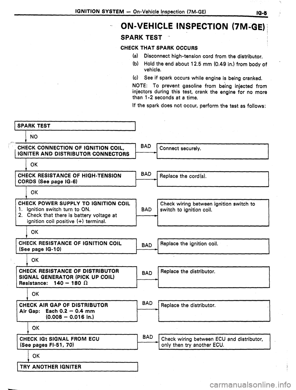
-. ON-VEHICLE INSPECTION (7M43E)‘;
SPARK TEST --
CHECK THAT SPARK OCCURS
(a) Disconnect high-tension cord from the distributor.
(b) Hold the end about 12.5 mm (0.49 in.) from body of
vehicle.
(G) See if spark occurs while engine is being cranked.
NOTE: To prevent gasoline from being injected from
injectors during this test, crank the engine for no more
than l-2 seconds at a time.
If the spark does not occur, perform the test as follows:
SPARK TEST
1
NO
,‘.
CHECK CONNECTION OF IGNITION COIL, BAD
Connect securely.
IGNITER AND DISTRIBUTOR CONNECTORS c
OK
CHECK RESISTANCE OF HIGH-TENSION
CORDS (See page IG-6) ’ BAD
Replace the cord(s).
OK
CHECK POWER SUPPLY TO IGNITION COIL
1. Ignition switch turn to ON.
2. Check that there is battery voltage at
ignition coil positive I+) terminal. Check wiring between ignition switch to
BAD
switch to ignition coil.
OK
CHECK RESISTANCE OF IGNITION COIL
(See page IG-10) 9
BAD Replace the ignition coil.
*
OK
1 , , 1
CHECK RESISTANCE OF DISTRIBUTOR
SIGNAL GENERATOR (PICK UP .COIL)
Resistance: 140 - 180 sz
OK BAD Replace the distributor.
m
CHECK AIR GAP OF DISTRIBUTOR
Air Gap: Each 0.2 - 0.4 mm
(0.008 - 0.016 in.) BAD
Replace the distributor.
L
OK
CHECK IGt SIGNAL FROM ECU
(See pages FI-51, 70) BAD
Check wiring between ECU and distributor,
only then try another ECU.
OK
t ,
TRY ANOTHER IGNITER
1 i
Page 260 of 346
IGNlTliiN SYSTEM - On-Vehicle Inspection (7M-GE)
It059 ‘6
IG059
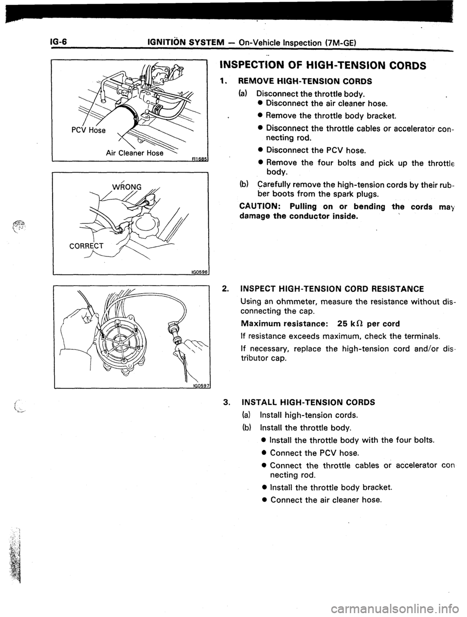
INSPECTiON OF HIGH-TENSION CORDS
1. REMOVE HIGH-TENSION CORDS
(a) Disconnect the throttle body.
l Disconnect the air cleaner hose.
l Remove the throttle body bracket.
0 Disconnect the throttle cables or accelerator con-
necting rod.
l Disconnect the PCV hose.
0 Remove the four bolts and pick up the throttle
body.
(b) Carefully remove the high-tension cords by their rub-
ber boots from the spark plugs.
CAUTION: Pulling on or bending the cords ma)
damage the conductor inside.
2. INSPECT HIGH-TENSION CORD RESISTANCE
Using an ohmmeter, measure the resistance without dis-
connecting the cap.
Maximum resistance: 25 kS2 per cord
If resistance exceeds maximum, check the terminals.
If necessary, replace the high-tension cord and/or dis-
tributor cap.
3. INSTALL HIGH-TENSION CORDS
(a) Install high-tension cords.
(b) Install the throttle body.
l Install the throttle body with the four bolts.
l Connect the PCV hose.
0 Connect the throttle cables or accelerator con
netting rod.
l Install the throttle body bracket.
0 Connect the air cleaner hose.