TOYOTA CELICA 1987 Service Manual PDF
Manufacturer: TOYOTA, Model Year: 1987, Model line: CELICA, Model: TOYOTA CELICA 1987Pages: 346, PDF Size: 35.13 MB
Page 71 of 346
EFI SYSTEM - Troubleshooting with’ Volt/Ohmmeter (MA) FI-37
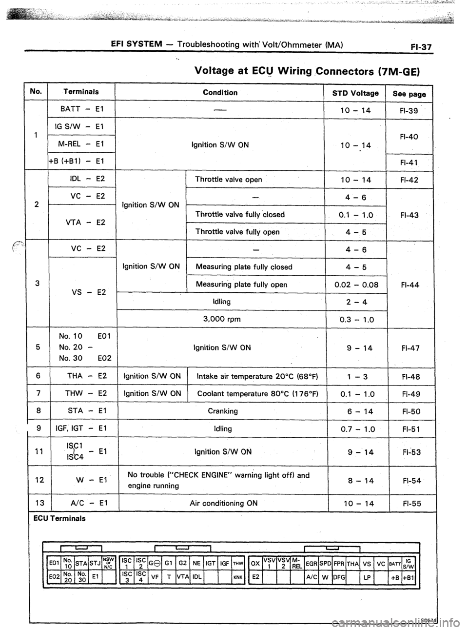
Voltage at EClJ Wiring .Connectors (TIM-GE)
IO. Terminals
Condition STD Voltage
See page
BATT - El
10 - 14 FI-39
IG S/W - El
1 FI-40
M-REL - El
Ignition S/W ON 10 - 14
+B (+Bl) - El FI-41
IDL - E2 Throttle valve open 10 - 14 FI-42
vc - E2 -
4-6
2 Ignition S/W ON -
Throttle valve fully ‘closed 0.1
- 1.0 FI-43
VTA - E2
Throttle valve fully open 4-5
VC - E2 4-6
Ignition S/W ON
Measuring plate fully closed 4-5
3 Measuring plate fully open 0.02 - 0.08 FI-44
VS - E2
Idling 2-4
3,000 rpm 0.3 - 1.0
No. 10 EOI
5 No. 20 - Ignition S/W ON 9 - 14 FI-47
No. 30 E02
6 THA - E2 Ignition S/W ON Intake air temperature 20°C (68°F) 1 -3 FI-48
7 THW - E2 Ignition S/W ON Coolant temperature 80°C II 76’F) 0.1 - 1 .O
FI-49
8 STA - El Cranking
6 - 14 FI-50
9 IGF, IGT - El Idling
0.7 - 1.0 FI-5 1
11 ISCI
I&4 - El Ignition S/W ON 9-14 Fl-53
12 W - El No trouble (“CHECK ENGINE” warning light off) and
engine running 8 - 14 FI-54
13 A/C - El Air conditioning ON IO - 14 FI-55
ECU Terminals
‘~,~] E2 4
/UC W:G up +S :,:I
N:y Is’ Is’ GO Gl G2 NE IGT IGF THW OX “s, “;“riL EGR SPD FPR THA VS VC BATT IG
F1057
Page 72 of 346
EFI SYSTEM - Troubleshooting with Volt/Ohmmeter (MA)
. .
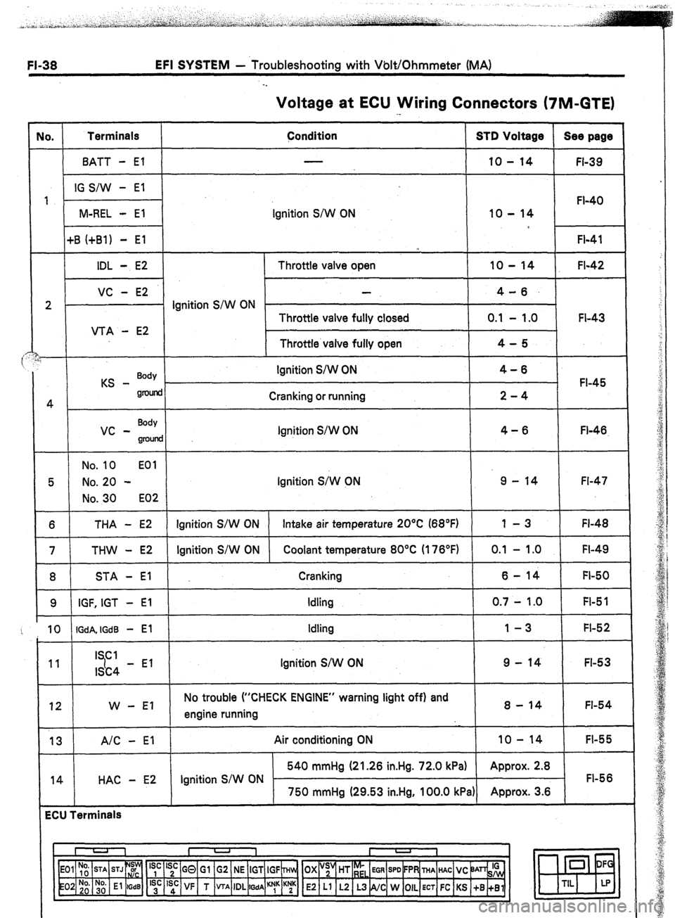
Voltage at ECU Wiring Connectors (7M-GTE)
No. Terminals
Condition STD Voltage Sea page
BATT - El 10 - 14
FI-39
IG S/W - El
1
FI-40
M-REL - El Ignition S/W ON 10 - 14
+B (+Bl) - El
FI-41
*
IDL - E2 Throttle valve open 10 - 14 FI-42
VC - E2 4-6.
2 . Ignition S/W ON
Throttle valve fully closed 0.1 - 1.0 FI-43
VTA - E2
Throttle valve fully open 4-5
i
KS - Body Ignition S/W ON 4-6
FI-45
gnMid
4 Cranking or running 2-4
vc - Body
Ignition S/W ON 4-6
groulld Fl-46.
No. 10 EOl
5 No. 20 - Ignition S;W CN 9 - 14 Fl-47
No. 30 E02
6 THA - E2 Ignition S/W ON Intake air temperature 20°C (68°F) 1 -3 FI-48
7 THW - E2 Ignition S/W ON Coolant temperature 80°C (176°F) 0.1 - 1 .O FI-49
8 STA - El Cranking 6-14 FI-50
9 IGF, IGT - El Idling 0.7 - 1.0 FI-5 1
10 IGdA, IGdB - El Idling 1-3 FI-52
11 I Cl
7 9 - 14 FI-53
ISC4 - El Ignition S/W ON
12 W - El No trouble (“CHECK ENGINE” warning light off) and
engine running 8 - 14 FI-54
13 A/C - El
14 HAC - E2 Air conditioning ON 10 - 14
FI-55
540 mmHg (21.26 in.Hg. 72.0 kPa) Approx. 2.8
Ignition S/W ON FI-56
750 mmHg (29.53 in.Hg, 100.0 kPa) Approx. 3.6
ECU Terminals
I U 1 I -
I
1
‘yc ‘;c GQ Gl G2 NE IGT IGF ~Hln, OX “;’ HT r;,
EGR SPD FPR THA HAC VC ‘JAn& 0 DF
‘;’ ‘sd: VF T VTA IDL
WA ““1” K;K E2 Ll L2 L3 NC W OIL ECT FC KS +B +Bl m
TIL LP
Page 73 of 346
EFI SYSTEM - Troubleshooting with~Volt/Ohmmeter (MA) FI-39
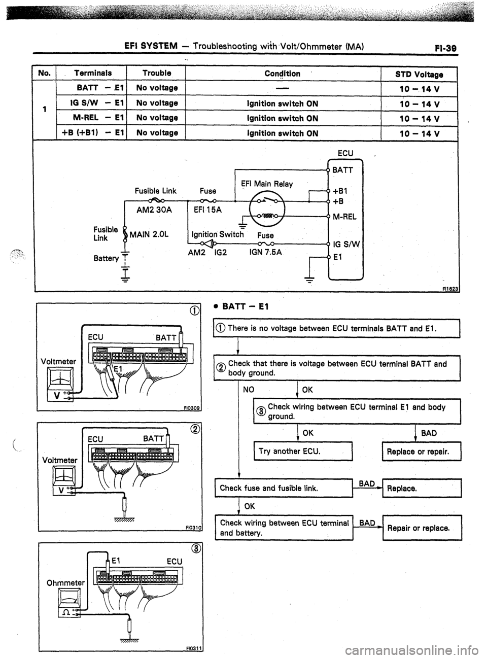
lo. Terminals Trouble
ConcJition
STD Voltage
I I
BAT1 -El No voltage
IO- l4V
1 IO S/W - El No voltage lgnitlon switch ON
10 - 14 v
1 M-REL - El 1 No voltage 1
ignition switch ON I IO-14v
1 +B (+Bl) - El1 No voltage
lgnitlon switch ON lo-14v
Fusible
Link
Battery ECU
Fusible Link +Bl
+B
M-REL
IG S/W
El
0 . BATT - El
@ There is no voltage between ECU terminals BATT and El.
I, ECU
BATT
Voltmeter
J V+ ECU BATT I!
n
1
0
Check that there is voltage between ECU terminal BATT and
body ground.
NO OK
0 Check wiring between ECU terminal El and body
ground.
I ’ I I I
Replace.
I OK
I I
I I I
I
Check wiring between ECU terminal BAD
and battery.
H Repair or replace.
I
I I I J
Page 74 of 346
FI-40 EFI SYSTEM - Troubleshooting with Volt/Ohmmeter (MA)
Voltmeter
Voltmeter
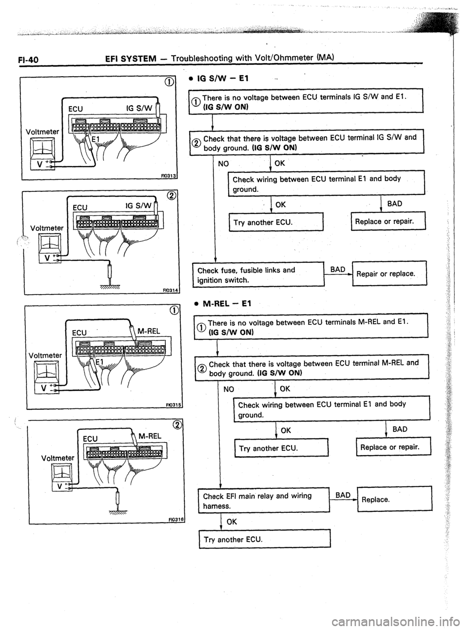
Ed ., + . IG S/W - El --
1
0 There is no voltage between ECU terminals IG S/W and El.
(IG S/W ON1
1
CD Check that there is voltage between ECU terminal IG S/W and
body ground. (IG S/W ON)
NO OK
Check wiring between ECU terminal El and body
ground.
’ OK
Try another ECU.
Check fuse, fusible links and BAD
Repair or replace.
. M-REL - El
0 There is no voltage between ECU terminals M-REL and El.
(IG S/W ON)
1
0 Check that there is voltage between ECU terminal M-REL and
body ground. (IG S/W ON)
NO OK
Check wiring between ECU terminal El and body
ground.
OK
Try another ECU.
I Replace or repair.
Check EFI main relay and wiring
harness.
I BAD
c Replace.
4
I Try another ECU.
I
Page 75 of 346
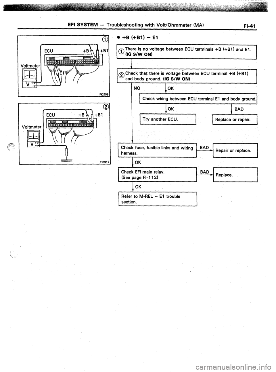
EFI SYSTEM - Troubleshooting with Volt/Ohmmeter (MA) FI-41
. +B (+Bl) - El
I 0
There is no voltage between ECU terminals +B
(IO SAN ON)
I
0 Check that there is voltage between ECU terminal +B (+Bl 1
and body ground. (IO S/w ON)
I I
NO OK
Check wiring between ECU terminal El and body ground.
OK
BAD
Try another ECU.
I Replace or repair.
1 I I
I
Check fuse, fusible links and wiring BAD
harness.
H Repair or replace.
I
I I I I I
1 OK I I I 1 Check EFI main relay.
(See page FI-1 12)
OK BAD
* Replace.
I
Refer to M-REL - El trouble
section.
I
Page 76 of 346
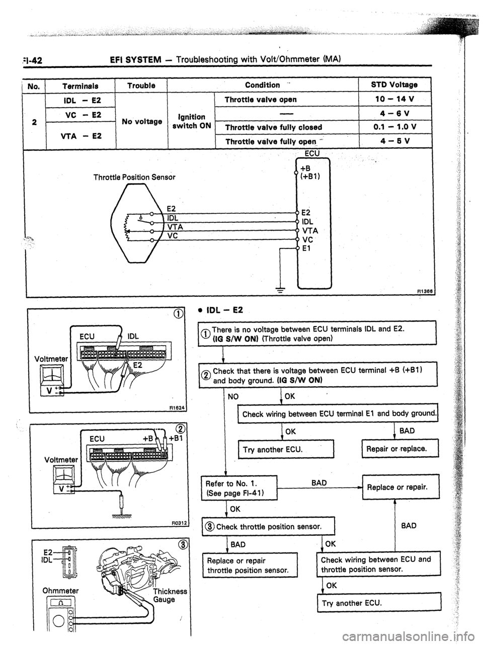
;I-42 EFI SYSTEM - Troubleshooting with Volt/Ohmmeter (MA)
NO, Terminals
IDL - E2 Trouble Condition ..
Throttle valve open STD Voltage
10 - 14 v
2 }-I No voltage / s$t;;N -
Throttle valve fully closed o.‘: I;,; v
I VTA - E2
I I Throttle valve fully c
I I I I
Throttle Position Sensor
Ei
I IDL
VTA
VC
El 4-5v
I
Voltmeter
R102,
FlO31
l IDL - E2
0 There is no voltage between ECU terminals IDL and E2.
(IO S/W ON) (Throttle valve open)
c
I
0 Check that there is voltage between ECU terminal +B (+Bl)
and body ground. (IO S/W ON)
c h
, 1
1 OK ’
1 1 Check wiring between ECU terminal El and body ground.1
t
Refer to No. 1.
(See page FI-41)
I
BAD
7
- Replace or repair.
1
b
OK
,
1
I@ Check throttle position sensor. 1 BAD
1
I BAD OK
.
Check wiring between ECU and
throttle position sensor.
1
Page 77 of 346
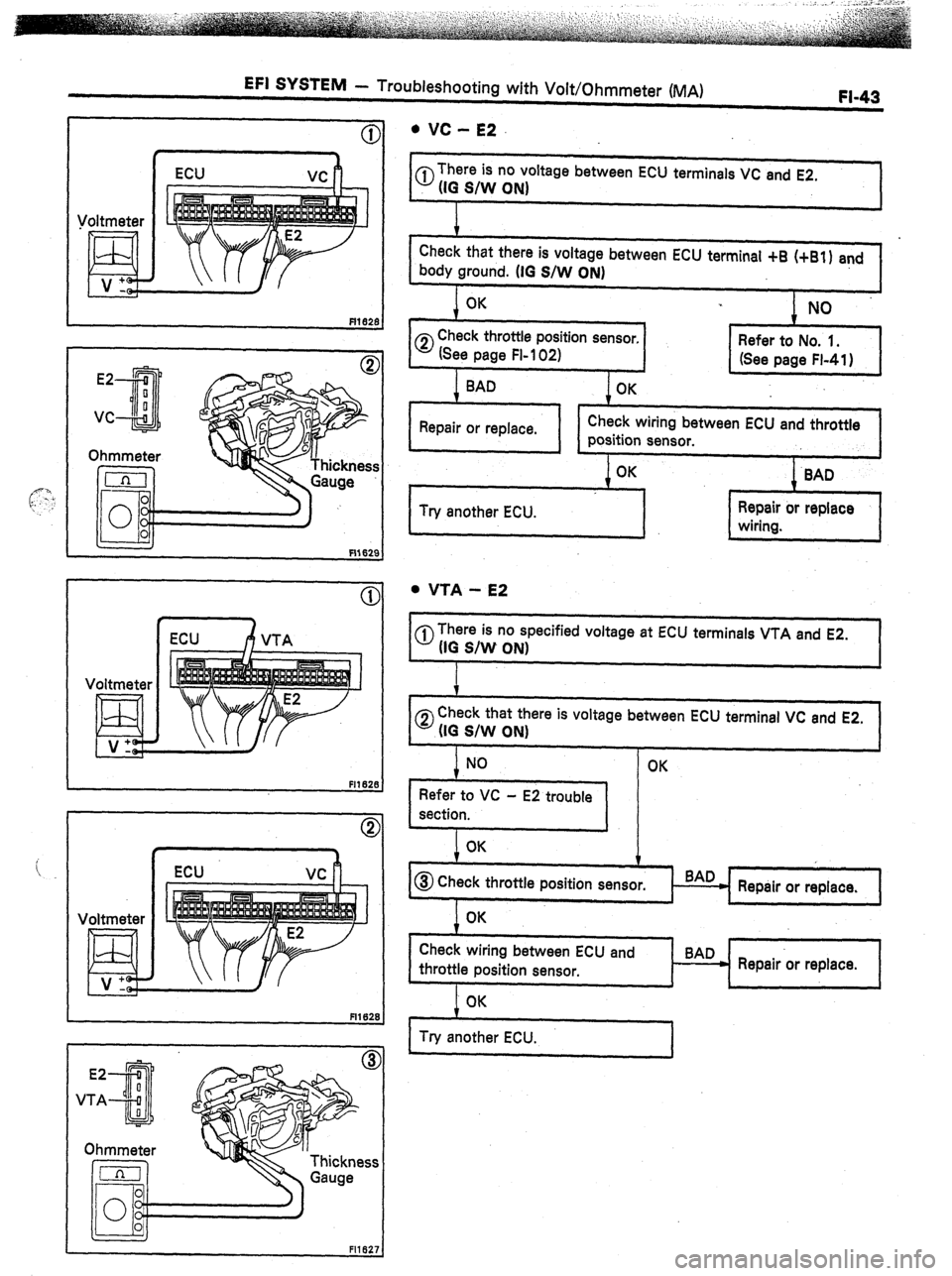
EFI SYSTEM - Troubleshooting with Volt/Ohmmeter (MA) FI-43
Voltmeter
El v:
(r:
c
cc
I ECU A VTA
Fll62f
Voltmeter
m ECU vc
l VC - E2
0 There is no voltage between ECU terminals VC and E2.
(IO
S/W ON)
1
Check that there is voltage between ECU terminal +6 (+El) and
body ground. (IO S/W ON)
OK
CD Check throttle position sensor,
(See page FI-102)
BAD
OK
I
I Repair or replace.
I 1 Check wiring between ECU and throttle
nosition sensor. I
I I I’
I I
1 OK
1 BAD
1 1
I I T
I
I Try another ECU. 1 :;;i. or replace 1
. VTA - E2
@There is no specified voltage at ECU terminals VTA and E2.
(IG S/W ON)
1
0
Check that there is voltage between ECU terminal VC and E2.
(IO S/W ON)
1 OK
t 1
7 I I
I
Check wiring between ECU and
BAD
throttle position sensor.
H Repair or replace.
I
1
J I I
I OK
I Try another ECU.
Page 78 of 346

WI4 EFI SYSTEM - Troubleshooting with Volt/Ohmmeter (MA)
No. Terminals Trouble Condition --
ST0 Voltage
I VC - E2
I
No voltage
vs - E2
‘7M-GE only 4-6V
Ignition
S/W ON Measuring plate fully closed 4-6V
Measuring plate fully open
0.02 - 0.08 V
Idling -.
2-4V
3,000 rpm
0.3 - 1 .o v
ECU
Air flow meter
Voltmeter
E3lL V’
Voltmeter
Air Flow Meter (j)
0 There is no voltage between ECU terminals VC or VS and E2.
IIG s/w ON)
i
1
0 Check that there is voltage between ECU terminal +B (+Bl)
and body ground. (IG S/W ON)
OK
NO
,
Refer to No. 1.
(See page FI-41)
I t 1 Check wiring between ECU terminal El and body ground. I 1
I OK
0 Check air flow meter.
(See page FI-96) 1 Repair or replace.
Check wiring between ECU and air
flow meter.
OK
Try another ECU. Repair or replace.
Page 79 of 346
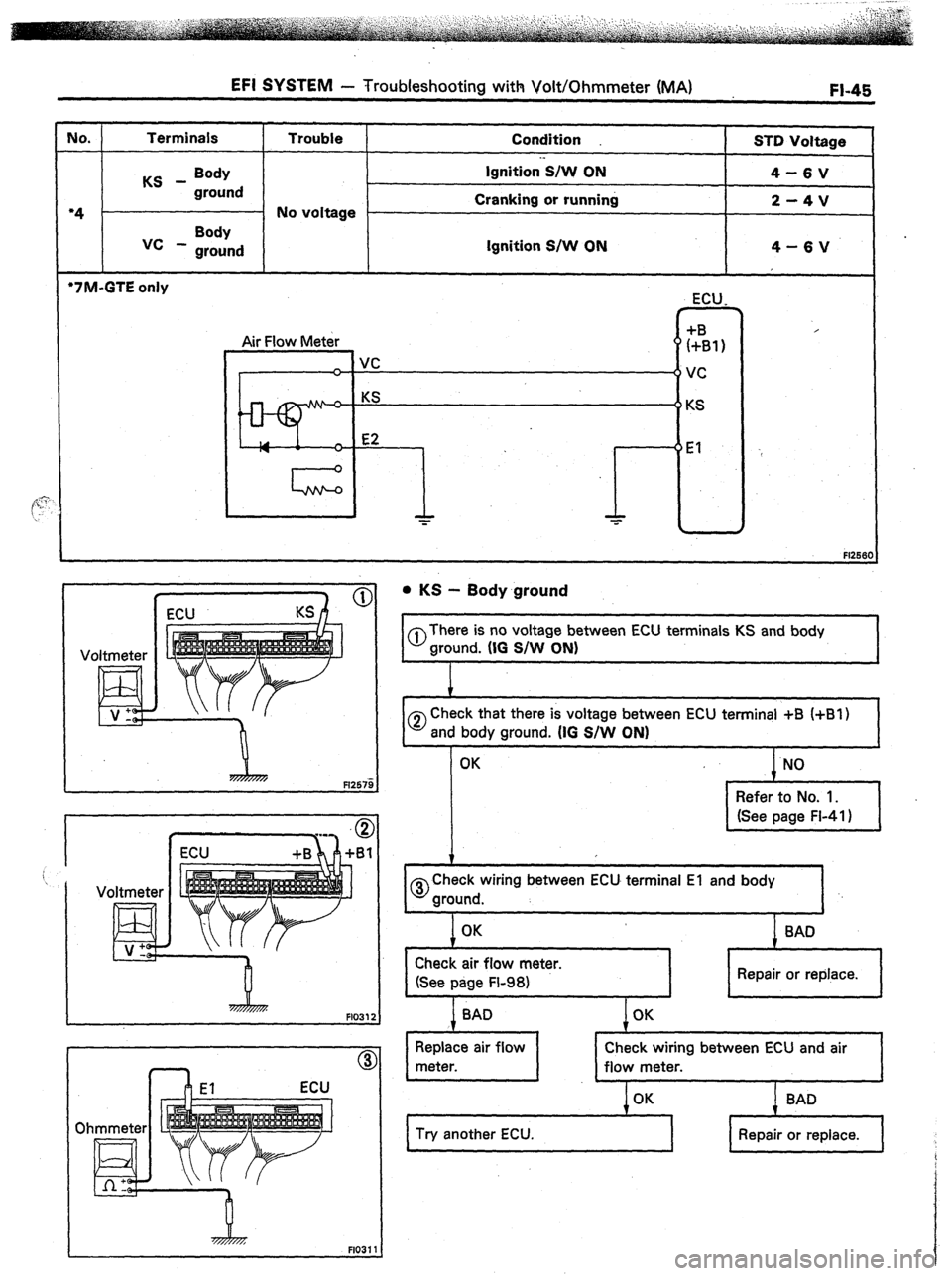
MO.
‘4 -
EFI SYSTEM - Troubleshooting with Volt/Ohmmeter (MA) FI-45
Terminals
Trouble
Condition
STD Voltage
KS - Body Ignition’S/W ON
4-6V
ground
No voltage Cranking or running
2-4V
I vc - Body
ground Ignition S/W ON
‘7M-GTE only
Air Flow Meter
_ Ivc ECU,
z31,
VC
KS
r El
FFA7m F1257i
Oh
. KS - Body ground
I 0
There is no voltage between ECU terminals KS and body
ground. (IO S/W ON)
I 0
Check that there is voltage between
and body ground. (IG S/W ON)
OK
i
0
Check wiring between ECU terminal El and body
ground.
OK
BAD
L
I
Check air flow meter.
(See page FL981
I I Repair or replace.
I
Check wiring between ECU and air
BAD
Try another ECU.
Repair or replace.
Page 80 of 346
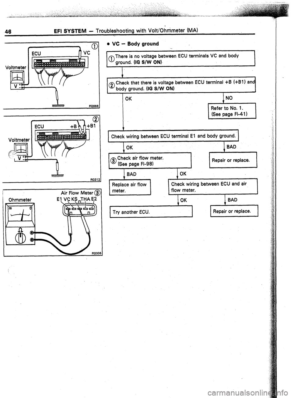
46 EFI SYSTEM - Troubleshooting with VoWOhnimeter (MA)
. .
Voltmeter
d V:
Voltmeter
Air Flow
Meter @
. vc - Body ground
al There is no voltage between ECU terminals VC and body
ground. (10 S/W ON),
0 Check that there is voltage between ECU terminal +B (+Bl) and
body ground. (IO
S/W ON)
Check wiring between ECU terminal El and body ground.
Check wiring between ECU and air
Try another ECU.