TOYOTA HIGHLANDER 2001 Service Repair Manual
Manufacturer: TOYOTA, Model Year: 2001, Model line: HIGHLANDER, Model: TOYOTA HIGHLANDER 2001Pages: 2572, PDF Size: 34.8 MB
Page 661 of 2572
2005 HIGHLANDER (EWD592U)
302
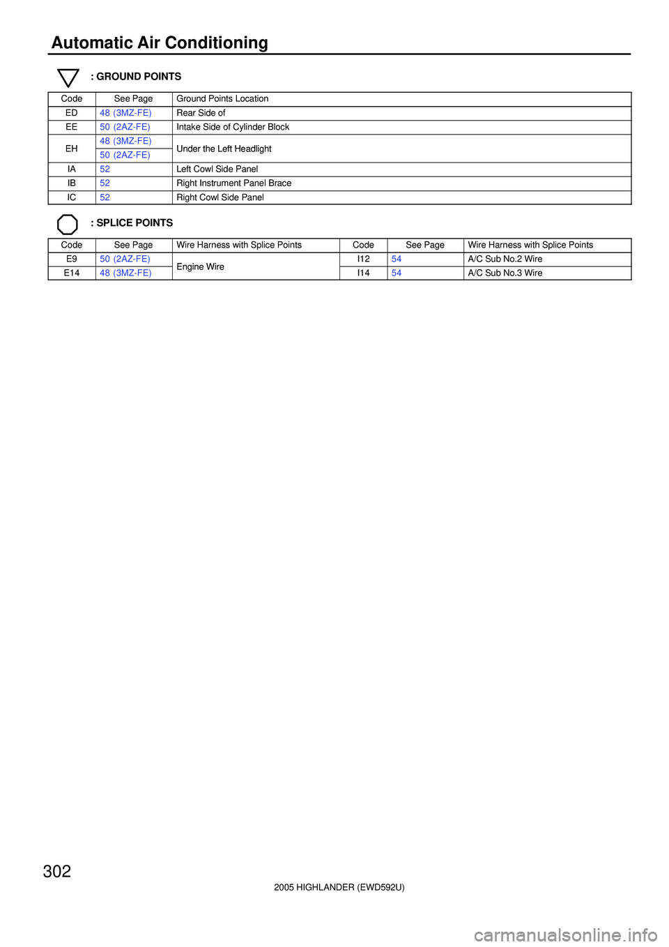
Automatic Air Conditioning
: GROUND POINTS
CodeSee PageGround Points Location
ED48 (3MZ-FE)Rear Side of
EE50 (2AZ-FE)Intake Side of Cylinder Block
EH48 (3MZ-FE)Under the Left HeadlightEH50 (2AZ-FE)Under the Left Headlight
IA52Left Cowl Side Panel
IB52Right Instrument Panel Brace
IC52Right Cowl Side Panel
: SPLICE POINTS
CodeSee PageWire Harness with Splice PointsCodeSee PageWire Harness with Splice Points
E950 (2AZ-FE)Engine WireI1254A/C Sub No.2 Wire
E1448 (3MZ-FE)Engine WireI1454A/C Sub No.3 Wire
Page 662 of 2572

2005 HIGHLANDER (EWD592U)
303
MEMO
Page 663 of 2572
2005 HIGHLANDER (EWD592U)
304
Manual Air Conditioning
50A HTR
7F 7
10A
HEATER
1K 13 1G 8
A A
A
25 413 IK4 1
I 6
OO
A 7
IA 8
423
1 456
II1 5 II1 4 II1 2
I13 1 2II1 1IG1 1
IC 4L 74H 7IG1 21
II16
3F 133J 6
IB 3J 10A 11 3J 73A 4
1K 21G 10
3I 113A 13
A 2A12 A13 IC3 57. 5A
ECU- B
2A 47. 5A
RAD
NO. 2
1K 3
Y
W- B W- B B B W- BWY
BR W BR
GR VBY
B
W- L
VB- Y
BR B W
O B- Y BW- B W- B
R- B
GR
W- B
W- BR
L
BR
W- BY
H 9 J 5
HR IG+ +B ACC
GND
B
LO
HI M2 M1 E
W- B W- B
B 8B 5
B 6
2IL2
MFrom Power Source System (
See Page 62)
A10(
A)
, A11(
B)
A/C Control Assembly
Blower Control SW
Blower Motor
Blower Resistor
Fusible Link
Block
Heater Relay Junction
Connector
Page 664 of 2572
2005 HIGHLANDER (EWD592U)
305
A 4A6A5
A13M
A14 54312B 14 B13 B10 B11 B12
IJ1 1
B Y- G
YGR
IJ1 2
OSB
IJ1 5
P- L O
IJ1 4
P
IJ1 3
I14
LG- R LG- R
IJ1 6
1 2B 5Y Y
LG G- Y LG- R
LG- R
B WY
MR/F AIF AIR AMH AMC TP S5- 1 SG- 1 TE 1416121312151154678910183
IG +B ILL+ ILL+ ILL- ILL- ACC 5V TEST SG BLK STX CLK DPD SWD HAZ GNDControl Panel
1 2 5A10(
A)
, A11(
B)
A/C Control Assembly
Air Inlet Control Servo Motor
Air Mix Control Servo Motor
Evaporator Temp.
Sensor E12
Page 665 of 2572

2005 HIGHLANDER (EWD592U)
306
Manual Air Conditioning
Y
B 2IL2 12
4A 54F 7 A 9
P 5G
BR
MPX+ MPX-
B 8B7B1B9B6
IL2 15 IL24IL213 IL23IL211
M 5 4123
V
G
B
BR
R GB WL LG
AOF AOD SG- 4 S5- 4 TPO
A153J 123E 1
B 1B2
A 1A2IB2 8MPX1 MPX2
IB2 1
IF3 5
(
*4)
G 5
8
24 22 MPD1
MPD2
R
R
GR R
V SB BR
BR
OYGR
7 11
MPX1 MPX2
A17
Y
Y
Y
O A 14
DIM DIM
T1 56
G SB
G
V (
*3)
(
*3)4
S30(
A)
, S31(
B)
A10(
A)
, A11(
B)
A/C Control Assembly
Air Vent Mode Control Servo Motor Airbag Sensor Assembly
Gateway ECU
Power Window Master SW
wi th ECU Short ConnectorTelltale Light Assembly
Page 666 of 2572
2005 HIGHLANDER (EWD592U)
307
B 29B 2
1B C2323 15 2A8
IK27
2C 22E3
IK3 18 IL2 1
EB2 9
IK3 2
EH A4 1
EE EDA A2 13
A 2
A 3
J 7
J 2B- R Y
SB GR
O
B- YY- G
Y- G
MG CLT
Relay
MPX2
L
W- L G W- B
BR BR BR
(
*2) (
*1)
* 1 : 3MZ- FE
* 2 : 2AZ- FE
PRE LCK1ACMG
Diode
(
Cooling Fan) Y- G
(
*1)
18 BMPX1
B 6
A 10MPX2 MPX1B 9A 21
MPX+ MPX-
OWY
Y
Y
O* 3 : w/ Navigation System
* 4 : w/o Navigation System
E 5(
A)
, E 6(
B)
, E 9(
C)
C11(
A)
, C12(
B)
DualB 9(
A)
, B10(
B)
A/C Magnetic Clutch
A/C Lock Sensor
Pr essure SW
Body ECUCombination Meter
Engine Control Module
Junction
ConnectorJunction
Connector
Page 667 of 2572
2005 HIGHLANDER (EWD592U)
308
Manual Air Conditioning
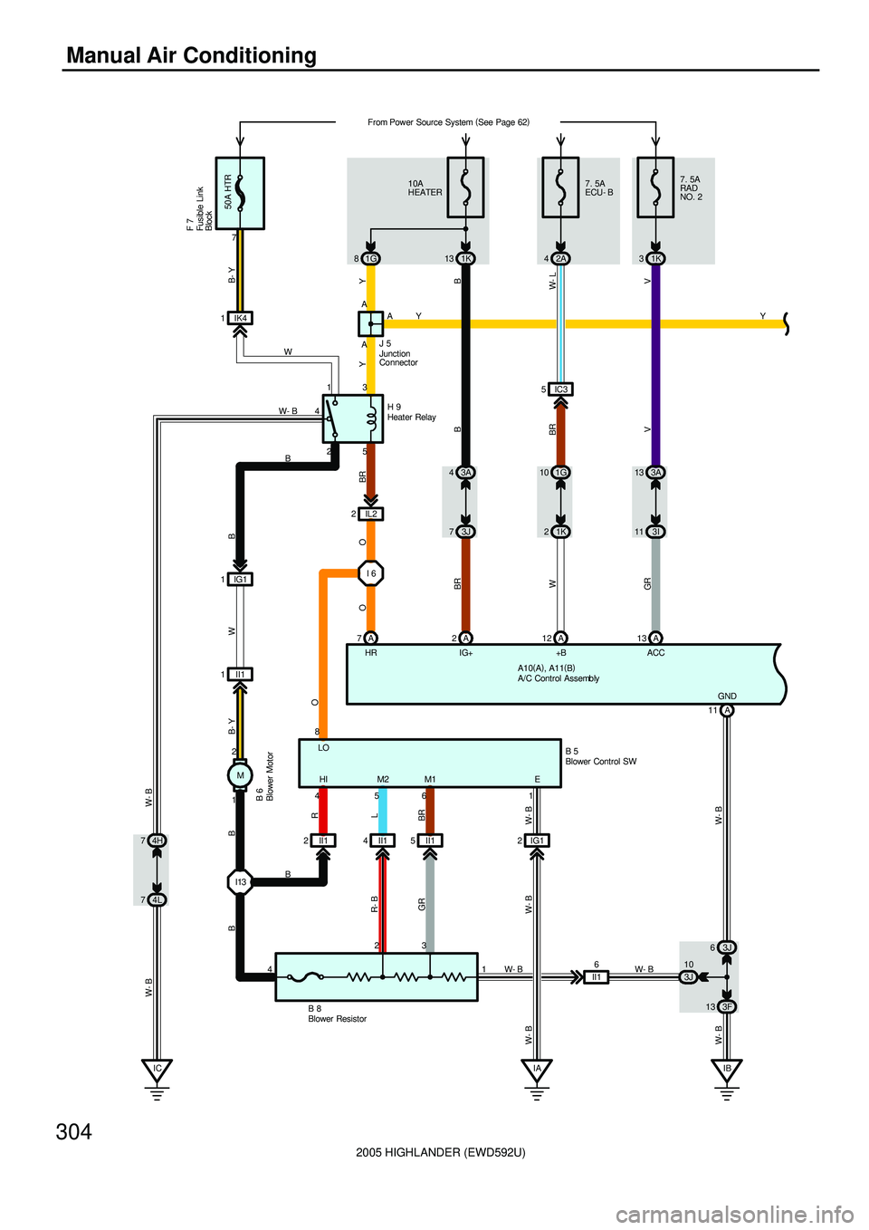
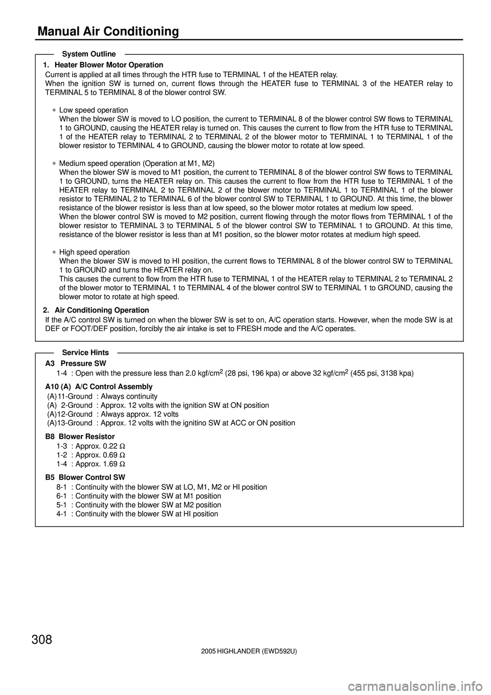
1. Heater Blower Motor Operation
Current is applied at all times through the HTR fuse to TERMINAL 1 of the HEATER relay.
When the ignition SW is turned on, current flows through the HEATER fuse to TERMINAL 3 of the HEATER relay to
TERMINAL 5 to TERMINAL 8 of the blower control SW.
*Low speed operation
When the blower SW is moved to LO position, the current to TERMINAL 8 of the blower control SW flows to TERMINAL
1 to GROUND, causing the HEATER relay is turned on. This causes the current to flow from the HTR fuse to TERMINAL
1 of the HEATER relay to TERMINAL 2 to TERMINAL 2 of the blower motor to TERMINAL 1 to TERMINAL 1 of the
blower resistor to TERMINAL 4 to GROUND, causing the blower motor to rotate at low speed.
*Medium speed operation (Operation at M1, M2)
When the blower SW is moved to M1 position, the current to TERMINAL 8 of the blower control SW flows to TERMINAL
1 to GROUND, turns the HEATER relay on. This causes the current to flow from the HTR fuse to TERMINAL 1 of the
HEATER relay to TERMINAL 2 to TERMINAL 2 of the blower motor to TERMINAL 1 to TERMINAL 1 of the blower
resistor to TERMINAL 2 to TERMINAL 6 of the blower control SW to TERMINAL 1 to GROUND. At this time, the blower
resistance of the blower resistor is less than at low speed, so the blower motor rotates at medium low speed.
When the blower control SW is moved to M2 position, current flowing through the motor flows from TERMINAL 1 of the
blower resistor to TERMINAL 3 to TERMINAL 5 of the blower control SW to TERMINAL 1 to GROUND. At this time,
resistance of the blower resistor is less than at M1 position, so the blower motor rotates at medium high speed.
*High speed operation
When the blower SW is moved to HI position, the current flows to TERMINAL 8 of the blower control SW to TERMINAL
1 to GROUND and turns the HEATER relay on.
This causes the current to flow from the HTR fuse to TERMINAL 1 of the HEATER relay to TERMINAL 2 to TERMINAL 2
of the blower motor to TERMINAL 1 to TERMINAL 4 of the blower control SW to TERMINAL 1 to GROUND, causing the
blower motor to rotate at high speed.
2. Air Conditioning Operation
If the A/C control SW is turned on when the blower SW is set to on, A/C operation starts. However, when the mode SW is at
DEF or FOOT/DEF position, forcibly the air intake is set to FRESH mode and the A/C operates.
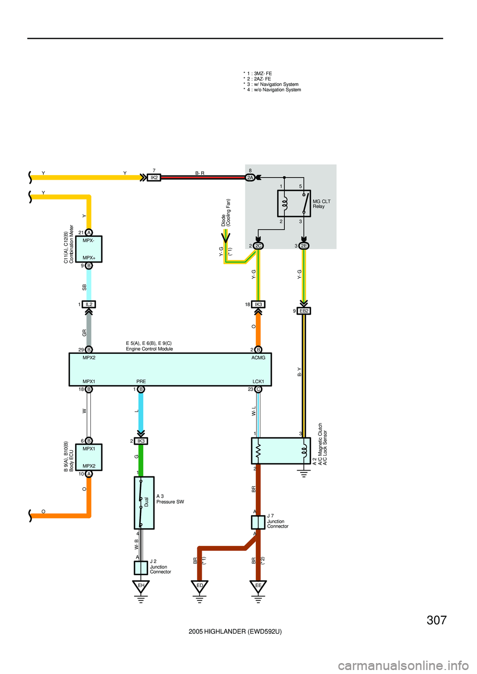
A3 Pressure SW
1-4 : Open with the pressure less than 2.0 kgf/cm2 (28 psi, 196 kpa) or above 32 kgf/cm2 (455 psi, 3138 kpa)
A10 (A) A/C Control Assembly
(A) 11-Ground : Always continuity
(A) 2-Ground : Approx. 12 volts with the ignition SW at ON position
(A)12-Ground : Always approx. 12 volts
(A)13-Ground : Approx. 12 volts with the ignitino SW at ACC or ON position
B8 Blower Resistor
1-3 : Approx. 0.22 W
1-2 : Approx. 0.69 W
1-4 : Approx. 1.69 W
B5 Blower Control SW
8-1 : Continuity with the blower SW at LO, M1, M2 or HI position
6-1 : Continuity with the blower SW at M1 position
5-1 : Continuity with the blower SW at M2 position
4-1 : Continuity with the blower SW at HI position
System Outline
Service Hints
Page 668 of 2572
2005 HIGHLANDER (EWD592U)
309
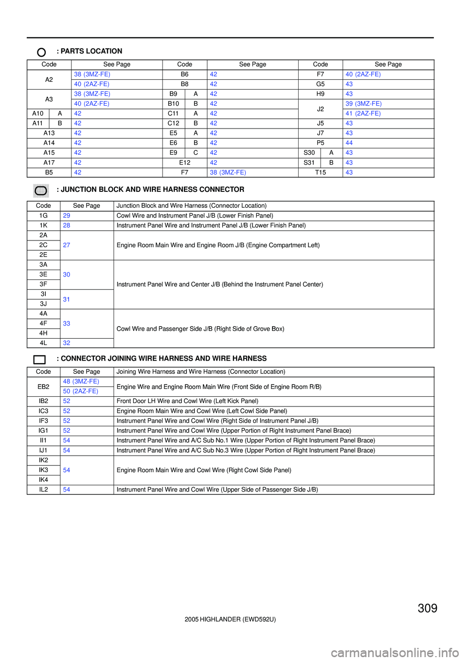
: PARTS LOCATION
CodeSee PageCodeSee PageCodeSee Page
A238 (3MZ-FE)B642F740 (2AZ-FE)A240 (2AZ-FE)B842G543
A338 (3MZ-FE)B9A42H943A340 (2AZ-FE)B10B42J239 (3MZ-FE)
A10A42C11A42J241 (2AZ-FE)
A11B42C12B42J543
A1342E5A42J743
A1442E6B42P544
A1542E9C42S30A43
A1742E1242S31B43
B542F738 (3MZ-FE)T1543
������ ���: JUNCTION BLOCK AND WIRE HARNESS CONNECTOR
CodeSee PageJunction Block and Wire Harness (Connector Location)
1G29Cowl Wire and Instrument Panel J/B (Lower Finish Panel)
1K28Instrument Panel Wire and Instrument Panel J/B (Lower Finish Panel)
2A
2C27Engine Room Main Wire and Engine Room J/B (Engine Compartment Left)
2E
gg(g)
3A
3E30
3FInstrument Panel Wire and Center J/B (Behind the Instrument Panel Center)
3I31
()
3J31
4A
4F33Cowl Wire and Passenger Side J/B (Right Side of Grove Box)4HCowl Wire and Passenger Side J/B (Right Side of Grove Box)
4L32
: CONNECTOR JOINING WIRE HARNESS AND WIRE HARNESS
CodeSee PageJoining Wire Harness and Wire Harness (Connector Location)
EB248 (3MZ-FE)Engine Wire and Engine Room Main Wire (Front Side of Engine Room R/B)EB250 (2AZ-FE)Engine Wire and Engine Room Main Wire (Front Side of Engine Room R/B)
IB252Front Door LH Wire and Cowl Wire (Left Kick Panel)
IC352Engine Room Main Wire and Cowl Wire (Left Cowl Side Panel)
IF352Instrument Panel Wire and Cowl Wire (Right Side of Instrument Panel J/B)
IG152Instrument Panel Wire and Cowl Wire (Upper Portion of Right Instrument Panel Brace)
II154Instrument Panel Wire and A/C Sub No.1 Wire (Upper Portion of Right Instrument Panel Brace)
IJ154Instrument Panel Wire and A/C Sub No.3 Wire (Upper Portion of Right Instrument Panel Brace)
IK2
IK354Engine Room Main Wire and Cowl Wire (Right Cowl Side Panel)
IK4
g(g)
IL254Instrument Panel Wire and Cowl Wire (Upper Side of Passenger Side J/B)
Page 669 of 2572
2005 HIGHLANDER (EWD592U)
310
Manual Air Conditioning
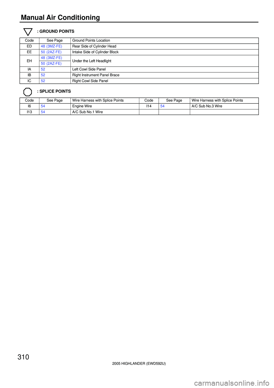
: GROUND POINTS
CodeSee PageGround Points Location
ED48 (3MZ-FE)Rear Side of Cylinder Head
EE50 (2AZ-FE)Intake Side of Cylinder Block
EH48 (3MZ-FE)Under the Left HeadlightEH50 (2AZ-FE)Under the Left Headlight
IA52Left Cowl Side Panel
IB52Right Instrument Panel Brace
IC52Right Cowl Side Panel
: SPLICE POINTS
CodeSee PageWire Harness with Splice PointsCodeSee PageWire Harness with Splice Points
I654Engine WireI1454A/C Sub No.3 Wire
I1354A/C Sub No.1 Wire
Page 670 of 2572

2005 HIGHLANDER (EWD592U)
311
MEMO